

Prints (0)
-
No Prints Yet
Be the first to upload a Print for this Design!
Description
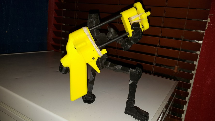
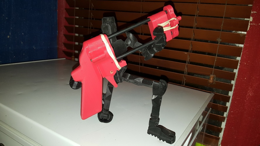
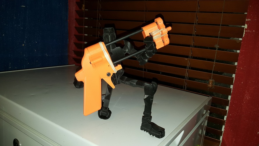
EZ-JENGA BLOCK SHOOTER
ALL PLAYERS SHOULD HAVE EYE PROTECTION!
BE AWARE OF YOUR SURROUNDINGS BLOCKS ARE MOVING VERY FAST!
Aim the EZ-SHOOTER at a block in the stack and POW that block is surgically removed from the stack!
This is a lot of fun to play JENGA with so you will need to make at least 2!
All of the parts are printed except the rods, screws and rubber bands...
parts list:
5 - printed parts. all of the parts should be printed at 50% fill or higher except the handle
2 - 1/4" rods 150mm. These can be wooden dowels, ABS rods or aluminum.
3 - 3mm x 15mm screws.
1 - 5mm x 20mm machine screw. This can be substituted with a piece of 5mm dowel 20mm long.
6 - #32 rubber bands.
Note: you will need to ream the holes for the rods/dowels to fit.Test fit all parts BEFORE you glue!
Step 1:
After you ream the holes.
Cut the rods/dowels to 150mm and remove any burrs.
Using CA (super glue) glue in the rods into the TRIGGER ASSEMBLY BLOCK and set aside.
Step 2:
When the glue is dry slid the KNOCKER on to the rods making sure the square side of the KNOCKER is in line with the trigger slot.
Test fit the FACE on the rods to see if the FACE sits parallel to the TRIGGER ASSEMBLY BLOCK, if they are parallel then glue them in place and set aside to dry. The KNOCKER should move very freely on the rods!
Step 3:
When the glue from step 2 is dry.
Take 2 rubber bands and put them through the hole and around the KNOCKER peg and put the loose end in the groove on the FACE.
Do the same thing going from the opposite side.
Step 4:
Place the TRIGGER in the groove with the latch facing the assembled rods.
The TRIGGER is held in place using the 5 x 20 machine screw.
Take 2 rubber bands one at a time and wrap them around the TRIGGER ASSEMBLY BLOCK.
The rubber bands should rest in the groove at the top and need to go around the hump on the trigger (see photo).
Step 5:
Use the 3 - 3mm x 15mm screws to attach the handle.
Now you are ready to have fun!!!
Note 2: the rubber bands that are going around the KNOCKER peg are a cushion when it is “dry fired” (not hitting a block).
If the TRIGGER won't hold the KNOCKER when it is cocked, tighten the rubber band that are going around the TRIGGER.
If the rubber bands come out of the grooves in the FACE use 2 - 2.5mm x 8mm washer head screw to keep them in the grooves with the holes that are next to the grooves.
If you would prefer not to glue the rods, you can use 2.5mm x 10mm screws to hold them in.
insert the rods in the TRIGGER BLOCK and the FACE run the screws in to mark the rods. Remove the rods and drill a hole through them at the marks and then reinstall with the KNOCKER in place.
Comments