Skip to content

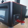
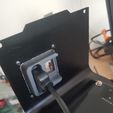
repositioning the USB port and the On/Off switch on the Elegoo Mars :

Advertising
Advertising
?
Creation quality: 0.0/5 (0 votes)
Evaluation of members on the printability, utility, level of detail, etc.

  • 786 views
  • 2 downloads

License
3D design format
Folder details Close
  • Elegoo_Mars_-_Repositionnement_USB__Power.rar
  • Instructions.txt
  • bouchon_usb_power.STL
  • gabarit.STL
  • plaque_support_usb_power_laterale.STL

Learn more about the formats

Publication date 2022-09-11 at 17:00
?
Published to Thingiverse on: 2020-08-23 at 15:45
Design number 841216

jamesdedij

3D printer file info

3D model description

repositioning the USB port and the On/Off switch on the Elegoo Mars :

A new USB cable is needed! The board has been designed for it ( Cost > 2.91 Eur.):

https://www.amazon.fr/gp/product/B00BR33Q6Y/ref=ppx_yo_dt_b_asin_title_o01_s00?ie=UTF8&psc=1

Parts to print:

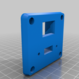
-The plate is to be printed preferably in PLA with at least 4 perimeters / 1.5mm for the tops/ bottoms/

30 to 40 % of filling.

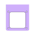
-The rear cap ( to plug the holes left by the inter and the USB port) and the template to the parameters

of your choice.

Realization:

-Dismantle the two casings.

-Remove the original USB cable.

-Remove the screen on the front housing.

-Apply tape (yellow paint job type) to the side of the front housing

which will be used to trace the cuts and protection.

-Apply and center the template on the tape at the desired position, then trace with a pencil

the holes and the contour of the cutout.

-Drill the 4 holes, either diam.3 (this will require to put nuts behind), or diam. 2.5mm

if you have this type of drill (this will allow tapping the sheet to M3).

-For interior cutting, use quality tools such as Dremel. You can make some

holes to pass a hacksaw blade. Finish with a fine file. CAUTION the sheet metal is easily deformed!

Protect it with a cloth if you put it in a vice!

-Remove the tape and clean the cutout (fine sandpaper) , tap if you drilled a 2.5.

-Disconnect the two lugs of the switch and extend the two wires of at least 30cms (CAUTION to use

an equivalent wire section ! Solder the wires ! And protect the soldering with thermo sleeve !

-Fix the new USb cable in the board, then fix the board on the housing and connect the cable to the motherboard.

-Pass the two wires of the switch through its housing, connect the lugs and retract the switch into its housing.

-Put the cap on the back.

-Reassemble the two housings!

AND THAT'S IT!

3D printing settings

-

Advertising


Page translated by automatic translation. See the original version.
Issue with this design? Report a problem.

Would you like to support Cults?

You like Cults and you want to help us continue the adventure independently? Please note that we are a small team of 3 people, therefore it is very simple to support us to maintain the activity and create future developments. Here are 4 solutions accessible to all:

  • ADVERTISING: Disable your banner blocker (AdBlock, …) and click on our banner ads.

  • AFFILIATION: Make your purchases online by clicking on our affiliate links here Amazon.

  • DONATE: If you want, you can make a donation via Ko-Fi πŸ’œ.

  • WORD OF MOUTH: Invite your friends to come, discover the platform and the magnificent 3D files shared by the community!


Sharing and downloading on Cults3D guarantees that designs remain in makers community hands! And not in the hands of the 3D printing or software giants who own the competing platforms and exploit the designs for their own commercial interests.

Cults3D is an independent, self-financed site that is not accountable to any investor or brand. Almost all of the site's revenues are paid back to the platform's makers. The content published on the site serves only the interests of its authors and not those of 3D printer brands who also wish to control the 3D modeling market.

100% secure payment by credit card, PayPal, Apple Pay, Google Pay, etc.
View all payment options.