https://youtu.be/0R3dhH1EhNQ
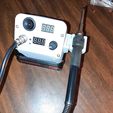
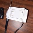
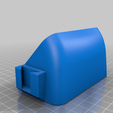
This is an adaptor and case to run an STC T12 soldering iron kit from a Black & Decker 20V MAX battery. It uses a soldering iron controller kit commonly available for about 15 USD on EBAY. It uses the kit with the 3 digit 7 segment led display. Since the kit doesn't have a low voltage cutoff for the Lion battery , I added a 2 wire voltage display also commonly available to moniter the battery voltage. There are 3 wire versions of this voltage moniter but I don't know if they will work.
The receptical for the battery is based on a project by "fcauwe" on printables.com called:
"Mobile power supply (DPS3005) with black and decker battery (freecad files included) "
https://www.printables.com/model/220415-mobile-power-supply-dps3005-with-black-and-decker-/files
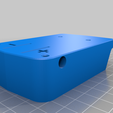
He include the freecad files , so I loaded them into freecad and exported them as step files. I then loaded the step files into F360 and was able to get the critical measurements from them. My receptical design is very similar to his. That was a lot easier than doing the measuring on the battery myself.
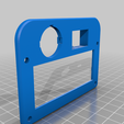
I assembled the soldering iron kit first to make sure it would work. I then realized I would have to desolder the avaition connector to assemble it to the front plate. Instead of desoldering the connector and maybe ruining the board , I just split the font plate in half so it can be assembled to the complete controller board.
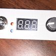
The voltage moniter is supposed to snap in to the bezel. Since PLA is kind of brittle you may break one or both of the prongs trying to snap it in. Mine holds with just one prong but hot glue would also hold it in. The front plate with the controller board is sandwiched in between the bezel and the case top.
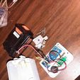
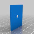
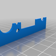
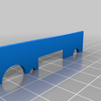
The contacts for the battery are made from brass sheet. The size is .032 or 1/32 inch or .8 MM. I used K&S brass from Hobby Lobby. I cut it with a hacksaw while it was clamped in a vise. You could also use some kind of tin snip or even a Dremel type tool. It is easy to cut yourself so be careful making this part. The hole is made with a 3MM drill. I have included a 3D printed template called contact to help in marking the part. You can fine tune the size with a file. To connect the battery contacts to the controller board the kit includes a connecter with 3 wires. The yellow wire is left unconnected. The red and black are for power. The case is designed for a 20MM diameter switch. A red wire from the battery is soldered to one terminal of the switch. The other terminal of the switch is soldered to the red wire of the connecter in the kit. The black wire goes directly to the negative battery contact. To connect the wires to the battery you can either solder wires to the contacts directly or use some type of connecter. I used 1/4 inch female spade connectors and shaped the battery contacts to accept them. If you solder the wire directly , make sure you do it before installing the contacts in the PLA part so you don't melt the PLA. The red wire of the voltage moniter is soldered to the same side of the on/off switch as the connecter that goes to the board. The black wire is spliced into the black wire of the same connector .
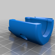
I printed the iron holder in PLA and so far no problems with heat. It mates to the case with a dovetail joint and is held on with a 3MM X 12MM screw. The battery receptical part has to be printed with supports but block the supports where the contact mounting screw holes are.
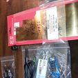
The parts needed to assemble this are:
Diy Soldering Iron Station Temperature Controller Digital for HAKKO T12 Handle
DC 3-30V LED Panel Voltmeter 3 Digital Display Voltage Meter
Round Rocker Switch ON/OFF Toggle Round Button 20MM
.032 inch (.8 MM) brass sheet
11ea 3MM X 12MM screws
Good instructions for building kit:
https://www.suhendro.com/2018/03/build-yourself-hakko-t12-compatible-soldering-iron-station/
Good luck.

/https://fbi.cults3d.com/uploaders/17518409/illustration-file/1eb05155-4364-47a4-acc2-8f2769ac2b91/cda6e577-1d16-406e-b036-cc6f09532143.jpg)
