Questo è un lavoro che sicuramente piacerà a molti. Iniziamo a dire che i kit sono compatibili con guide lineari MGN9C, MGN12C, MGN12H. Per ogni attacco guida lineare sono compresi quattro configurazioni di montaggio, piastra stock, piastra stock con collare (vedasi lavoro fatto su decentramento pcb), piastra nano, e piastra nano con collare, quindi avete una ampia scelta.
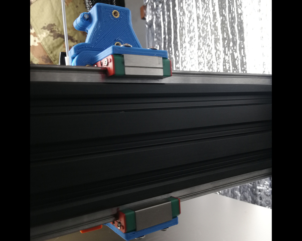
Ho creato questa configurazione con montaggio delle guide non al solito posto, di solito vengono montate 1 o 2 guide sul lato frontale del profilo X, secondo il mio pensiero il baricentro si sposta troppo in avanti dall’asse del profilo X pertanto con un montaggio a balcone il peso grava troppo. Quindi ho cercato di mantenere tutto in asse portando le guide ad un montaggio sul lato superiore e inferiore, così da non gravare, e avendo un attacco a mezza fascia, il supporto è più solido e il movimento sull’asse X risulta meno faticoso proprio perché il peso è distribuito sull’asse verticale.
Non ci sono problemi di spazio sia inferiori che superiori, il montaggio del supporto guide rientra nell’altezza della placca stock artillery.
Per i possessori X1 posso già dire che sopra si può montare un binario da 400mm, mentre sotto può essere di lunghezza compresa tra 350mm e 370mm, quindi o comprate le 350mm o tagliate (come ho fatto io) a 370mm o 350mm. Per Genius purtroppo dovete misurare voi.
Per possessori di X1 e Genius senza guide lineari montate su Z, questi devono usare guide lineari MGN9C per evitare urti alla massima estensione su Z e su X, invece chi ha già guide su asse Z può usare le MGN12C o MGN12H, avendo guide su Z, l’asse X si sposta di alcuni mm in avanti e c’è spazio per carrelli mgn più grandi (quindi fate attenzione a cosa scegliete non mi assumo responsabilità).
Ricordatevi 2 regolazioni da fare dopo il montaggio delle guide:
• Aggiungere se serve 1 o 2 anelli o rondelle di plastica sotto al sensore di fine corsa dell’asse X, guardare se è quasi al centro con il carrello di metallo stock per la rilevazione della distanza 0, per il sensore asse Z non ho avuto problemi di lettura;
• Il sensore Z trovandosi in coincidenza del binario inferiore, effettuerà la lettura su di esso, pertanto ricordatevi di abbassare il sensore Z tanto quanto l’altezza del binario.
Ho diviso i kit per tipo di guida quindi non potete sbagliarvi per ogni guida troverete nel file .rar sia file stl sia file step, sia file solidworks. L’assemblaggio non è complicato, per ogni configurazione metto foto in esploso, attenzione all’inserimento dei filetti in ottone (sono 2 modelli servono entrambi), e al verso di inserimento, quelli messi nell’attacco delle guide, devono uscire circa 1mm fuori (vedere le foto) queste fanno da guida per inserirsi nella placca stock, ho messo anche una foto in sezione di come viene inserito. Lo spazio è fatto apposta per favorire (senza esagerare) la trazione.
Specifico un punto su fori e tolleranze, di solito inserisco 1-2/10 di mm di tolleranze negli inserimenti e riduco con la stessa proporzione i fori dei filetti per le viti in modo che queste creino una filettatura o se sono passanti, siate voi a giocare dentro con la vite per portarlo a misura, nel caso dei fori posti dietro sugli attacchi delle guide, in particolare quelli che vanno a contatto con i dadi che escono dalla placca in metallo. Questi in certi casi con una punta da trapano 6,5 devono essere allargati a mano (non si rompe niente tranquilli), questo perché ho provato di persona l’attacco su 2 diverse placche di metallo, quella artillery stock, e una simile comprata a parte. Risultava che i dadi che fuoriuscivano dal posteriore avevano diametro differente pertanto non entrava, quindi come ho detto con una punta e un po di gioco leggerissimo a mano, se serve allargatelo.
Per il montaggio c’è poco da dire, le foto dicono tutto, gli inserti sono tutti m3, lo stesso per le viti (comprese sempre tra 6-12mm) quindi m3, e sono m3 anche i dadi u nuts per fissare le guide lineari al profilo di alluminio. Quindi seguite le foto e nel montaggio non stringete tutto e subito, così potete effettuare regolazioni e vedere se il carrello scorre bene.
Per il resto se avete bisogno chiedete, vi rispondo volentieri. Come sempre sperando di aver fatto cosa gradita per la comunità, vi ringrazio molto, se vi fa piacere, donazioni al prezzo di un caffè sono sempre gradite almeno per il tempo speso, e in caso pubblicate il tutto, per favore almeno citatemi e visitate la mia pagina instagram @nd_nanodesigner. Buon lavoro da “NANODESIGNER”.
ENGLISH
This is a job that will surely appeal to many. Let's start by saying that the kits are compatible with linear guides MGN9C, MGN12C, MGN12H. Four mounting configurations, stock plate, stock plate with collar (see work done on pcb offset), nano plate, and nano plate with collar are included for each linear guide mount, so you have a wide choice.
I created this configuration with mounting of the guides not in the usual place, usually 1 or 2 guides are mounted on the front side of the X profile, in my opinion the center of gravity moves too far from the axis of the X profile therefore with a mounting to balcony the weight is too heavy. So I tried to keep everything aligned by bringing the guides to an assembly on the upper and lower side, so as not to burden, and having a half-band attachment, the support is more solid and the movement on the X axis is less tiring precisely because the weight is distributed on the vertical axis.
There are no space problems both lower and upper, the mounting of the guide support falls within the height of the stock artillery plate.
For X1 owners I can already say that above you can mount a 400mm rail, while below it can be between 350mm and 370mm long, so either buy the 350mm or cut (as I did) to 370mm or 350mm. Unfortunately for Genius you have to measure yourself.
For owners of X1 and Genius without linear guides mounted on Z, these must use linear guides MGN9C to avoid collisions to the maximum extension on Z and on X, instead those who already have guides on the Z axis can use the MGN12C or MGN12H, having guides on Z , the X axis moves a few mm forward and there is room for larger mgn trolleys (so be careful what you choose I don't take responsibility).
Remember 2 adjustments to make after mounting the guides:
• Add if you need 1 or 2 plastic rings or washers under the X axis limit switch, check if it is almost in the center with the stock metal trolley for the 0 distance detection, for the Z axis sensor I did not have reading problems;
• The Z sensor, being coincident with the lower track, will carry out the reading on it, so remember to lower the Z sensor as much as the height of the track.
I have divided the kits by type of guide so you can not go wrong for each guide you will find in the .rar file both stl files, step files, and solidworks files. The assembly is not complicated, for each configuration I put exploded photos, pay attention to the insertion of the brass threads, (there are 2 models you need both), and to the direction of insertion, those placed in the attachment of the guides, must come out about 1mm out (see photos). as a guide to fit into the stock plate, I also put a sectional photo of how it is inserted. The space is made on purpose to favor (without exaggerating) the traction.
I specify a point on holes and tolerances, I usually insert 1-2 / 10 of mm of tolerances in the insertions and I reduce with the same proportion the thread holes for the screws so that they create a thread or if they are through, you play inside with the screw to bring it to size, in the case of the holes placed behind the guides attachments, in particular those that come into contact with the nuts that come out of the metal plate. These in some cases with a 6.5 drill bit must be widened by hand (nothing breaks, don't worry), this is because I personally tested the attachment on 2 different metal plates, the artillery stock one, and a similar one bought at part. It turned out that the nuts that came out from the rear had a different diameter and therefore did not enter, so as I said with a bit and a bit of very light play by hand, if you need to enlarge it.
For assembly there is little to say, the photos say it all, the inserts are all m3, the same for the screws (always between 6-12mm) then m3, and the u nuts to fix the linear guides are also m3. to the aluminum profile. So follow the photos and in the assembly do not tighten everything right away, so you can make adjustments and see if the carriage runs smoothly.
For the rest, if you need to ask, I will gladly answer you. As always hoping to have done something pleasant for the community, thank you very much, if you like, donations for the price of a coffee are always welcome at least for the time spent, and if you publish everything, please at least mention me and visit the my instagram page @nd_nanodesigner. Good work from “NANODESIGNER”.
List of material at the end of the document.
:format(webp)/https://fbi.cults3d.com/uploaders/26105973/illustration-file/a5a5fdf4-587f-4e17-8970-45e424c394b7/5.JPG)


/https://preview3d-images.cults3d.com/lxnf321rncgjrwqtl5wxy67k90vw)
/https://preview3d-images.cults3d.com/c9o366vu4dmokjjdwdzlagms21uz)
/https://preview3d-images.cults3d.com/ohmxh8uh5311j94qirj2a89qiux7)


