This is not an all inclusive "How-to" but rather an explanation of how I made and assembled the rifle. This airsoft gun is rather advanced and is not simple to make. It will require a lot of modification, mechanical ingenuity, plenty of airsoft teching experience and general DIY'ing patience.
The modifications necessary to turn the TR16 into a No Time To Explain cannot be reversed unless you are willing to buy a new lower receiver and gearbox! Start by dissembling the rifle and gearbox completely and start sawing. The lower receiver will need to have the buffer tube mount and part of the trigger area removed, see the pictures for clarification. The gear box will also need to be chopped up to allow the battery and FCU to live in the rear of the receiver behind the F2. The bottom of the gear box where the motor came in will need to be cutoff flush to make the bottom of the gearbox flat, this will free up space to mount the HPA quick disconnect fitting. Depending on where you decide to mount your safety/fire select switch you may need to also cut away parts of the side of the gearbox, see the pictures to see the chunk I took out of the side of mine in order to mount the safety switch through the original fire selecter lever hole. Next, the stock flash hider/muzzle device and mock gas block will need to be removed from the end of the gun. After that you will have to drill a hole through the barrel nut so you can run the wires from the trigger up front under the keymod rail, to the back of the gun where the FCU is. Lastly the charging handle and dust cover will need to be removed.
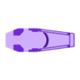
The suppressor on the gun is in 3 parts, the End, Core and Skirt. These are made to be assembled with countersunk head screws and then the barrel extension screws into the back of the Skirt. There are no threads in the Skirt but it has been sized to be a nice snug fit and in my experience has no problem being threaded onto the extension as it cuts its own threads. Before placing the suppressor on the gun, slide the Barrel Brace down into the rail section around the barrel. One of the 4 flanges doesn’t have a notch in it, this one goes towards the top, the notches on the side and bottom permit the keymod hardware to pass through the rail. With the Barrel Brace pressed in install the suppressor with barrel extensions and attach keymod rails along the bottom of the rail. You will need enough to cover the whole bottom.
Put the grenade launcher together. The Nozzle piece glues into the end of the Front piece and then can be slid over the barrel section of the launcher. The fit should be snug but can be fixed in place with glue. The Rear part attaches to the back of the grenade launcher with the two forward screws, they just clamp to the part. The two rear screw holes are just decoration. Make sure you take the safety off the launcher (place in fire) before installing the Rear portion as you cannot reach the safety when its installed. The Rear portion can also be fixed in place with a little glue.
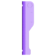
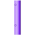
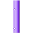
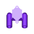
Assemble the trigger by placing the SPEED trigger and switch in the Pistol Mount and covering it with the Tigger Cover. Route the wires through the top of the Mount and in through the rail and barrel nut before attaching the Mount to the keymod rails. Placement is not critical, just place it far enough in front of the magwell so you have enough room to hold the pistol grip comfortably. Screw on the AEG grip the same way you would to a gearbox and attach the Pistol Base to the bottom of the grip like you would a motor plate. Screw in the Trigger Brace to the front of the Mount using the screw holes along the side. You can now route the 3/8 plastic tube from the holes in Brace to the holes in the Base. The exact length will depend on how much bend you want in the tube. Cut, fit and try again till you like the shape of the bend in the tube.
With the whole trigger assembly in place, you can mount the grenade launcher. The exact placement is not critical, just make sure there is enough room behind it to comfortably reach the grenade’s trigger on the back of the launcher.
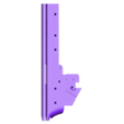
The parts that decorate the sides of the rail have “Port” and “StarB” in their names. The parts with Port go in the left side of the gun and parts with StarB (starboard) go on the right side of the gun. Start with the Side Rails, then the Flanks, and then the Angle parts. Because the parts slide into the rail from the rear and then slide forward to lock into the keymod slots you need to install the most forward parts first. The angled parts are in three pieces, The Angle Fore, Angle Rear and Diagonal. The Diagonal part is the same left and right so just print two of them. These three pieces have a step in them so they align themselves so you can glue them together. The assembled parts can then be attached to the trigger and rail.
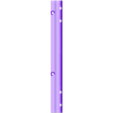
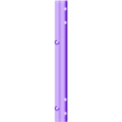
The Upper parts can be installed on top of the rail. They have multiple holes along the side to run screws into the rail. The top of the rail has a bunch of holes in it so I placed a bunch of holes along the length of the Upper so that even minor variations in placement can result in some of the holes lining up with a solid portion of the rail for drilling and screwing. Three Antennas each side can be glued or drilled and screwed into the Upper. There are no markings for placement of the Antennas.
On top of the gun you can slide the Cheek Forward and Cheek Rest onto the top of the gun. Using the holes in the tops of the parts, drill holes into the top of the rail and receiver to run a screw through to fix them in place. Exact placement is not critical, just make sure they are far enough forward so that the Butt Stock fits. The Butt stock has holes in its sides but this is just a press fit onto the back of the receiver. The HPA Plate fits on the bottom of the lower receiver and has four holes along the sides for drilling and screwing into the lower receiver. The large hole at the bottom of the Plate allows you to attach an HPA QD fitting and macro line press fit connector. Screw them together from opposite sides to clamp down on the HPA Plate. With the gearbox and F2 installed, trim the macro line to length so that it just reaches the press fit connector. Theres not a lot of room in the gun so this fit may take a couple tries.
Wiring the gun is the only tricky part. With the trigger in the front half of the gun it’s advisable to the use a small connector between the trigger and FCU so you can take the gun apart without damaging the wires. Placement of your safety/ fire selector is up to you, I chose to run a switch out the side of the lower receiver.
Cable color code is as follows:
Black - Top Solenoid
White - Bottom Solenoid
Red - Fire Selector
Blue - Trigger
Brown - Ground (common)
Enjoy your new gun and paint it up any color scheme you like!
Parts Required:
G&G TR16 308 Rifle (Keymod version)
PolarStar F2
Madbull 40mm Grenade Launcher
7.2V lipo battery
MAXX HopUp
455mm EDGI 6.01 Stainless Barrel
60 Degree Maple Leaf Bucking
SPEED Trigger (V2)
100mm 14mmCCW Barrel Extension
3/8” Plastic tube
Keymod rails (enough to line the bottom of the rail)
AEG grip (from donor gun)
Others:
Misc wires, connectors and air fittings
Assorted M3 hardware
Keymod rail hardware

/https://fbi.cults3d.com/uploaders/24018693/illustration-file/a16ec223-ce46-4475-81c5-d254e523c89e/1.jpg)


