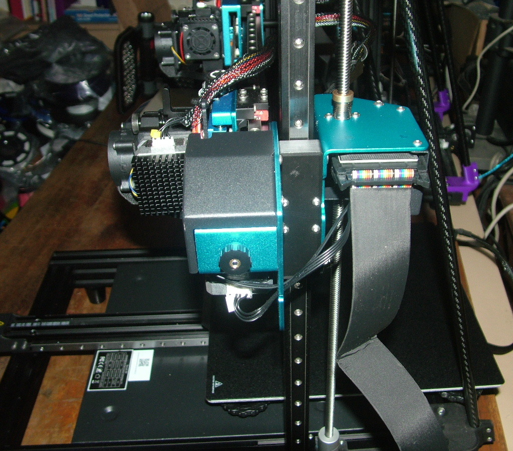
Here is one way to add linear rails to a Sovol SV04. This is not the only way and may not be the best way but it's a way.
Each axis can be done independently so it's not required to do them all at once as good linear rails are not cheap. However for the X and Z axes you'll need to strip the printer down quite thoroughly so even though not required, it makes sense to do them at the same time.
The choice of whether to use socket head cap screws or button head screws is up to you. I think button heads look better for exposed screws heads but they both work equally well.
Notes:
When I say to discard a part that's no longer needed I mean stick it in the spare parts box not throw it in the bin.
If any holes in the printed parts are a touch small, just run an appropriate size drill through them (bolts are all M3 or M5).
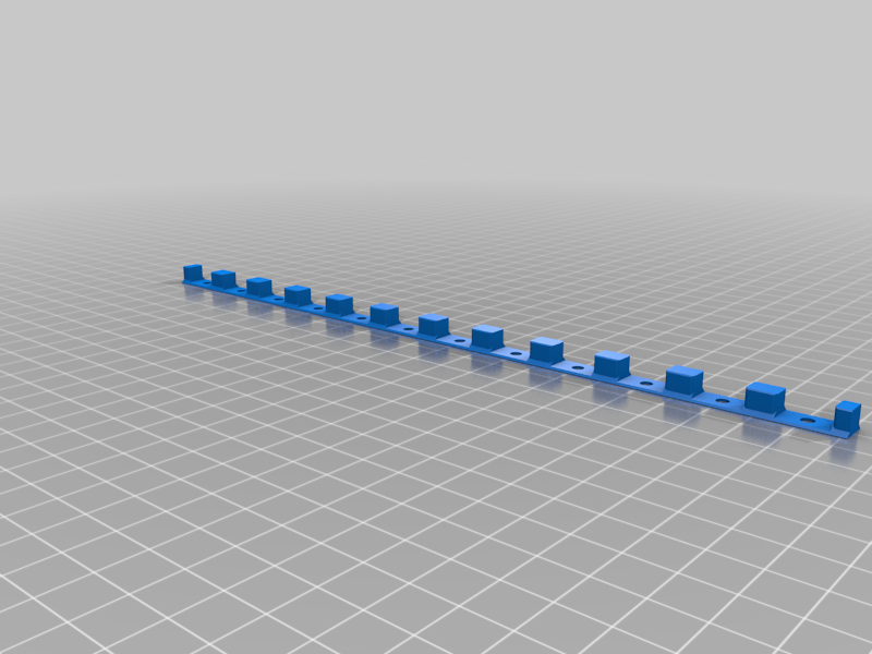
Alignment jigs
Included are two jigs to align the rails (MGN9 and MGN12) to the center of the v-slot extrusion when mounting. You don't need to bolt them together but it makes it easier to be certain everything is centered and solid while doing up the mounting screws. Use two jigs on each rail.
Each jig needs:
* 4 x M5x35 screws
* 4 x M5 nuts
You can of course use any of the numerous other alignment jigs available.
X axis
You will need
- 2 x 480mm MGN9 rails (500mm are the easiest to find and just trim a bit off the ends)
- 4 x MGN9C blocks
- 64 x M3x8 screws if you use every mounting hole on the rails.
- 48 x M3 t-nuts for 20 v-slot extrusion if you use every rail mounting hole
- 8 x M3x30 screws
- 4 x M3 nuts
Print
- X_LeftExtrTop
- X_LeftExtrBtm
- X_RightExtrTop
- X_RightExtrBtm
- 2 x X_Spacer
- 4 x X_VSlotFiller
Disassembly
Remove the X assembly. Either remove the Z rods, take off the top rail and slide it off the top or remove the whole gantry, remove the stepper motors and rods and slide it off the bottom.
Remove the front and rear cover plates at each end.
Unscrew the breakout boards and snip all the cable ties.
Remove the right extruder (four screws on the right: two top, two bottom) and take it off with all the wiring and put aside.
Remove the left extruder (three screws on the left: two top, one bottom) and take it off but be careful as the touch probe wiring will still be attached to the probe. Remove the four screws that hold the front part of the mounting plate on (one in each corner) and pull the front plate off with the extruder and all wiring. Set it aside. Discard the four corner mounting screws.
Undo the five screws from the back of the right mounting plate that hold the two parts of it together and remove the front section and set aside. Discard the screws.
Remove all wheels and their mounting bolts and discard.
The drive belt for the right extruder can stay on if you like but it will make it easier if it comes off so the 2040 extrusion can be taken off completely to be worked on.
The left extruder mounting plate needs to come off to have the corner holes drilled out so undo its drive belt.
Unscrew the 2040 extrusion from the end plates.
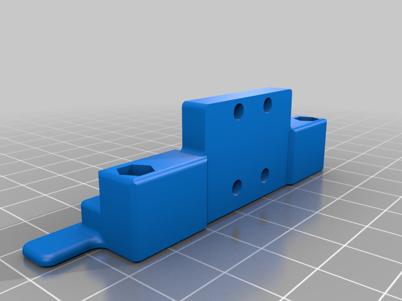
On each extruder mounting plate remove the little tab that is the optical end stop trigger and rear cable support and discard. The end stop trigger is built into the new top brackets and you lose the cable support (I've found it does nothing anyway, especially if you have additional cable management supports).
Modifications
Left extruder plate: Drill out the 4 threaded holes in the corners to 3mm or slightly larger (3.2mm should be plenty).
Assembly
For the rails, use the 4 printed extrusion slot fillers. These are needed to mount the 9mm rails in 9mm wide slots. The top of the slot filler should be flush with the v slot extrusion. Attach the fillers to the rails loosely with 8mm screws and t-nuts then drop into the slot. Use MGN9 alignment jigs to center the rails when tightening.
Place the printed spacers between the 2040 extrusion and the end plates. Their purpose is to allow enough clearance for the blocks to be able to pass in front of the plates. The extruders are moved closer to the gantry to compensate for this slight offset.
Mounting of the top and bottom block brackets should be self explanatory.
Reverse the disassembly steps to get it all back together.
When attaching the drive belts to the mounting plates, loosely screw the plates to the blocks so they stay roughly in place. This will make it much easier to attach the belts, unless you have three hands.
Z Axis
You will need
- 2 x 500mm MGN12 rails
- 2 x MGN12H blocks
- 40 x M3x8 screws if you use every mounting hole on the rails.
- 40 x M3 t-nuts for 20 v-slot extrusion if you use every rail mounting hole
- 8 x M3x16 screws
Print
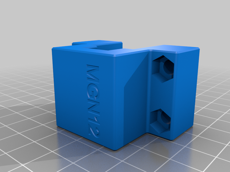
- 2 x Z_Block
- 2 x Z_Spacer
- Z_Jig_PlateDrill
Disassembly
As per the X axis but you don't need to remove the extruders.
Remove the X stepper motors from the end plates.
Remove the end plates.
Remove and discard all the wheels and spacers. Keep the nuts and bolts.
Modifications
Use the jig to drill new 5mm mounting holes in both the front and rear plates. The holes that need redrilling are the ones where the outer wheels are normally mounted. Move the two outer holes outwards in each plate.
Assembly
Bolt the rails on using the MGN12 alignment jigs.
Replace the inner wheels and their bushes with the spacers. The spacer has a step on one end, this end goes in the larger hole where the offset bush originally sat.
Mount the MGN12H blocks in their brackets.
Slide the blocks onto the rails.
Reattach the X extrusion to the end plates and put the whole assembly back onto the uprights.
Slide the block brackets into place and attach with the original bolts.
Important The top outer bolt must be reversed from its original orientation so the head is at the back and the nut at the front. If this is not done the nut will interfere with the breakout board. The bottom bolt doesn't matter.
You could bolt the blocks in before remounting the whole assembly but it's fiddly to get them onto the rails without losing any ball bearings and they are a bugger to find when they fall out and shoot across the floor.
Finish putting it all back together.
Y Axis
You will lose 4.5mm of z travel (honestly, not that big a deal) unless you work out a way to drop the control box at least 4mm or move it somewhere else. It's really much easier just to raise the Y axis a tiny bit.
You will need
- 2 x 450mm MGN12 rails
- 4 x MGN12H blocks
- 52 x M3x8 screws if you use every mounting hole on the rails.
- 36 x M3 t-nuts for 20 v-slot extrusion if you use every rail mounting hole
Print
- Y_Carriage
- Y_Jig_PlateDrill
- Y_Jig_StepperDrill
- 2 x Y_Spacer
Disassembly
Remove the build plate.
Remove the Y rail.
Unhook the drive belt, remove all wheels and bushes and discard. Keep the nuts and bolts.
Remove the stepper motor and mounting bracket.
Modifications
Use the plate jig to drill new 5mm holes in the mounting plate.
Use the stepper jig to redrill the bottom mounting hole in the stepper motor mounting bracket. Drill either, or both, new holes (if you use both you'll need an extra M5x8 bolt and M5 t-nut).
Assembly
Bolt the rails on using the MGN12 alignment jigs.
Attaching the blocks and carriage should be self explanatory. Use the original bolts that were used to mount the wheels.
Remount the whole assembly using the spacers between the Y extrusion and the main frame.
:format(webp)/https://fbi.cults3d.com/uploaders/14461763/illustration-file/4d28d883-194d-4b3c-8ade-5f8faee5e1e9/DSCF8451.JPG)


/https://preview3d-images.cults3d.com/4bsjxja9uz7zh5th1l32btbs7aqr)
/https://preview3d-images.cults3d.com/8z3n7qi1n9pes8uztzlpfjhhbdcv)
/https://preview3d-images.cults3d.com/0upzxq84ohxp080a1wirfl2ccnrr)
/https://preview3d-images.cults3d.com/r87h49ahrmhsmjlbojtsth8p2oro)
/https://preview3d-images.cults3d.com/krqvuj5awprpg79d9h1opopimqw8)
/https://preview3d-images.cults3d.com/54s2lb5vojpz650dx2yusz6w5pmu)
/https://preview3d-images.cults3d.com/6er238pmk633mji4583rax9vx5na)
/https://preview3d-images.cults3d.com/9n3slkke58r21tg05h1jta9tv8j4)
/https://preview3d-images.cults3d.com/0k1uj3hhwu07kverykspjlt5hfxr)
/https://preview3d-images.cults3d.com/xeifm40j0p5djrj5satbj088beow)
/https://preview3d-images.cults3d.com/axtyjsr9xg3st2jbnyhfn8apypu6)
/https://preview3d-images.cults3d.com/n8fh5872skorfedi4jrxmyfqe7ee)
/https://preview3d-images.cults3d.com/9hjs0hrhzhhqc4ef5arizq49ltuy)
/https://preview3d-images.cults3d.com/mwrh8qntg13rr3bgzcd9u3dr6c4y)
/https://preview3d-images.cults3d.com/1qj0rvcnkigrmdpv5d4xt7hng465)
/https://preview3d-images.cults3d.com/aepkikjx2d82ybb8n1g0i0gxf52q)
/https://preview3d-images.cults3d.com/uuoqvuk0ursmj1ttnl5wmkxuxpmo)


