MyDigitalSlot Race System Video
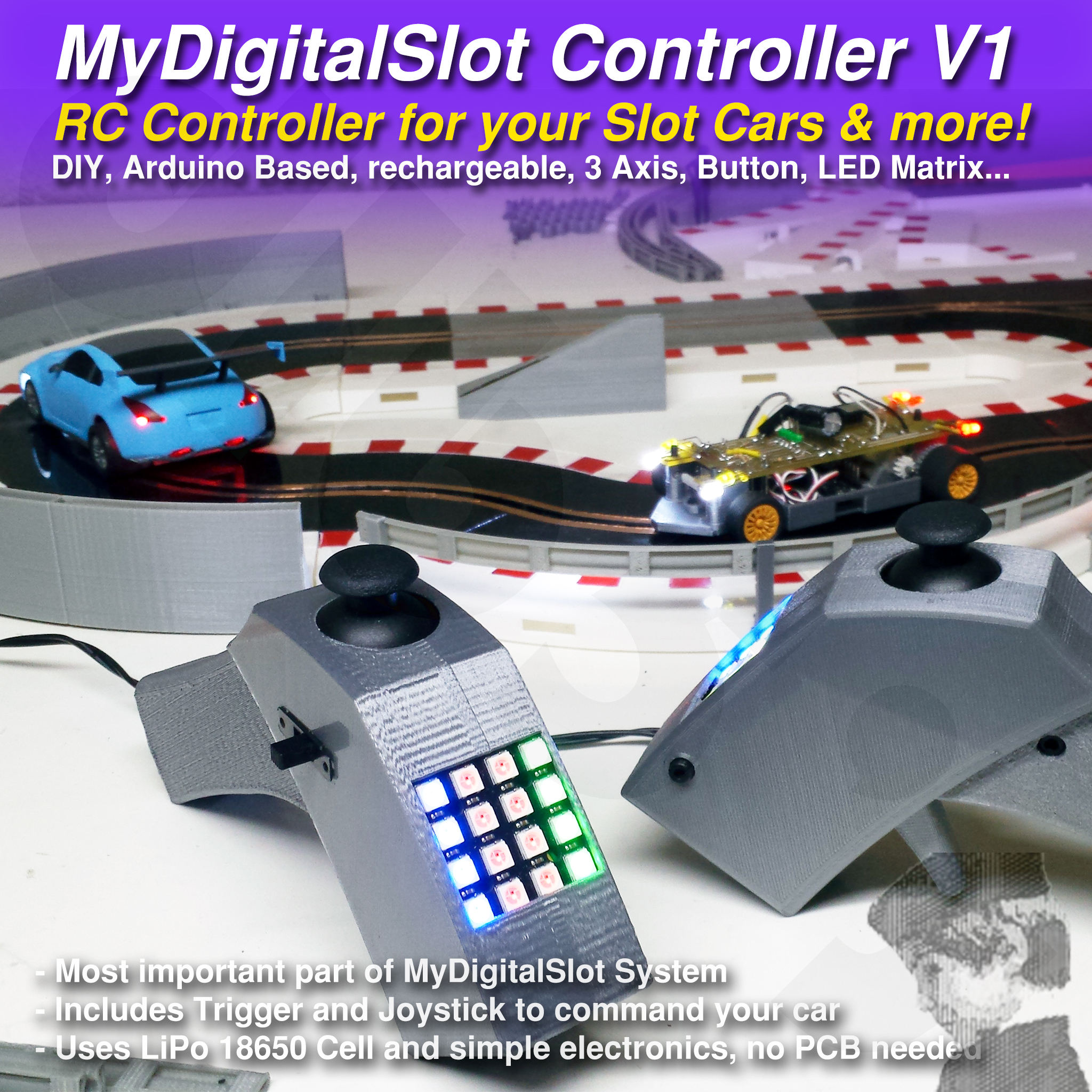
With the STLs and indications in this publication, you will be able to print and build the MyDigitalSlot Basic Controller V1 you can see in the above and next video
MyDigitalSlot Story, Part 2 Video
This piece of the MDS System is probably the most important, at less it is where I have spent more time, specially with code.
It is made with easy to find electronic hardware, requires NO PCB, and it is BASIC because it is what I consider enough to interact with the car and with the other controllers.
The same you can control the MDS cars, you could control other RC vehicles or gadgets, maybe your electrified Long Board?¿?
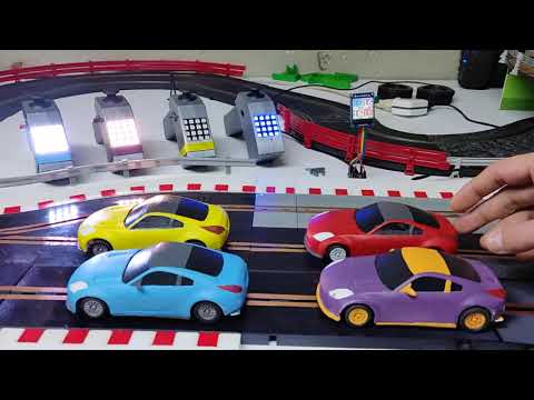
As I hope you have seen in the first video, I have made four of these and linked each one to a car and a color.
FEATURES:
- Arduino based RF communication
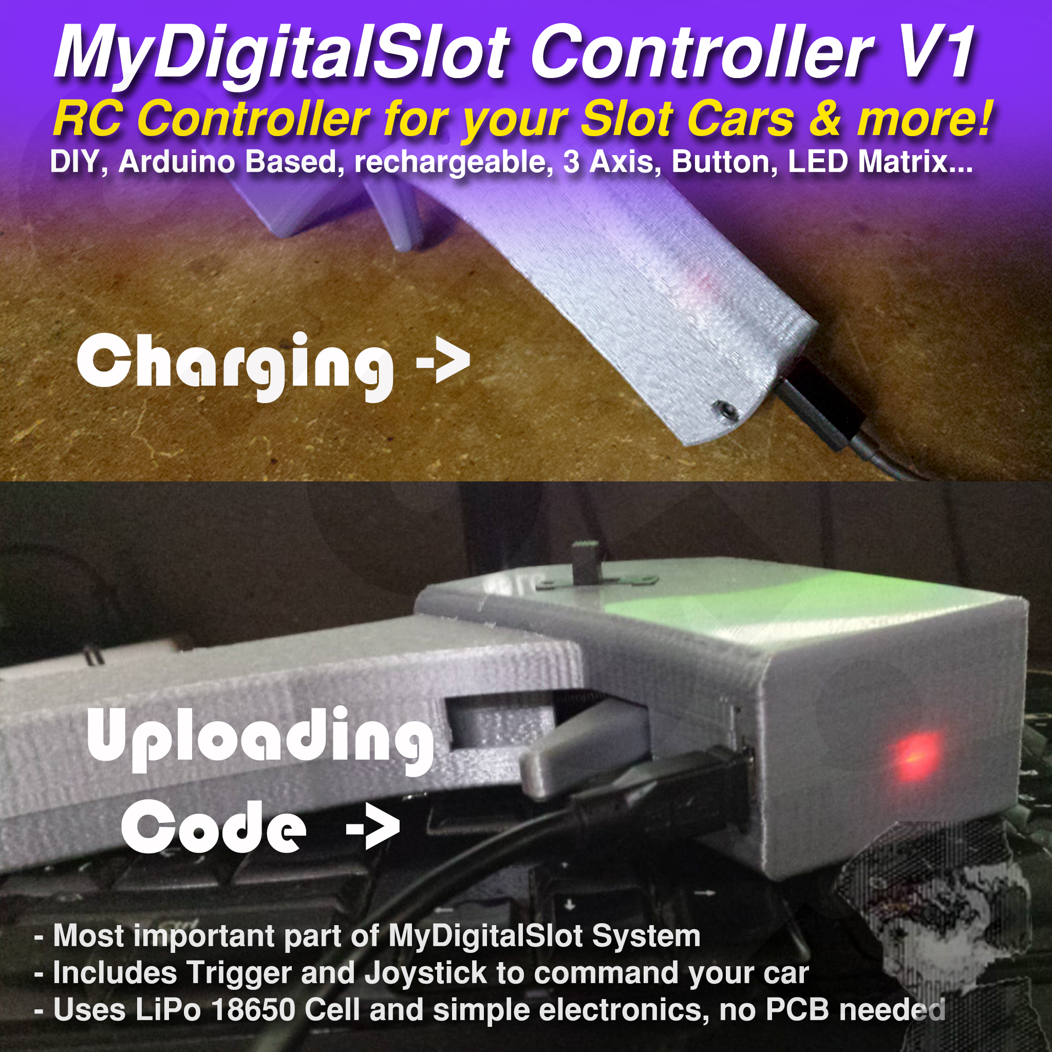
- Rechargeable, uses Li-Po 18650 cell as power source (the ones in laptop batteries)
- Responsive Throttle Trigger, using Clipper lighter Spring
- Informative, thanks to the 4x4 RGB led matrix
- Interactive, with two extra joystick axis and the joystick's clic button
- "Ergonomic", at less more than my "BigBoy Radio" ;)
- Easily re-programable, with the Arduino's USB accessible without un-assembling
BOM:
- 1x Arduino RF-Nano, the black ones recommended
- 1x UPS 1-cell LiPo Module
- 1x 5050 4x4 Led Matrix
- 1x Joystick for arduino
- 10cm Female-Female Dupont cables
- 1x 10K Potenciometer
- 1x Sliding Switch
- 1x 10x15x4 Bearing
- 1x Clipper Lighter Spring
- 2x M3x8 or M3x10 Counter-Sunk Screws
- 2x M3x16 Socket Head Screws
- 1x M3x20 Socket Head Screw
I added the links to the products I bought, but I'm sure you can find same specs and size products nearer but probably not cheaper.
ASSEMBLY
It is not the hardest build in the world but you will need some skills, like soldering, accurate 3D printing and a minimum of electronics knowledge to better know what you are doing, but anyway I will tell you as much as I can to ensure you build it up correctly.
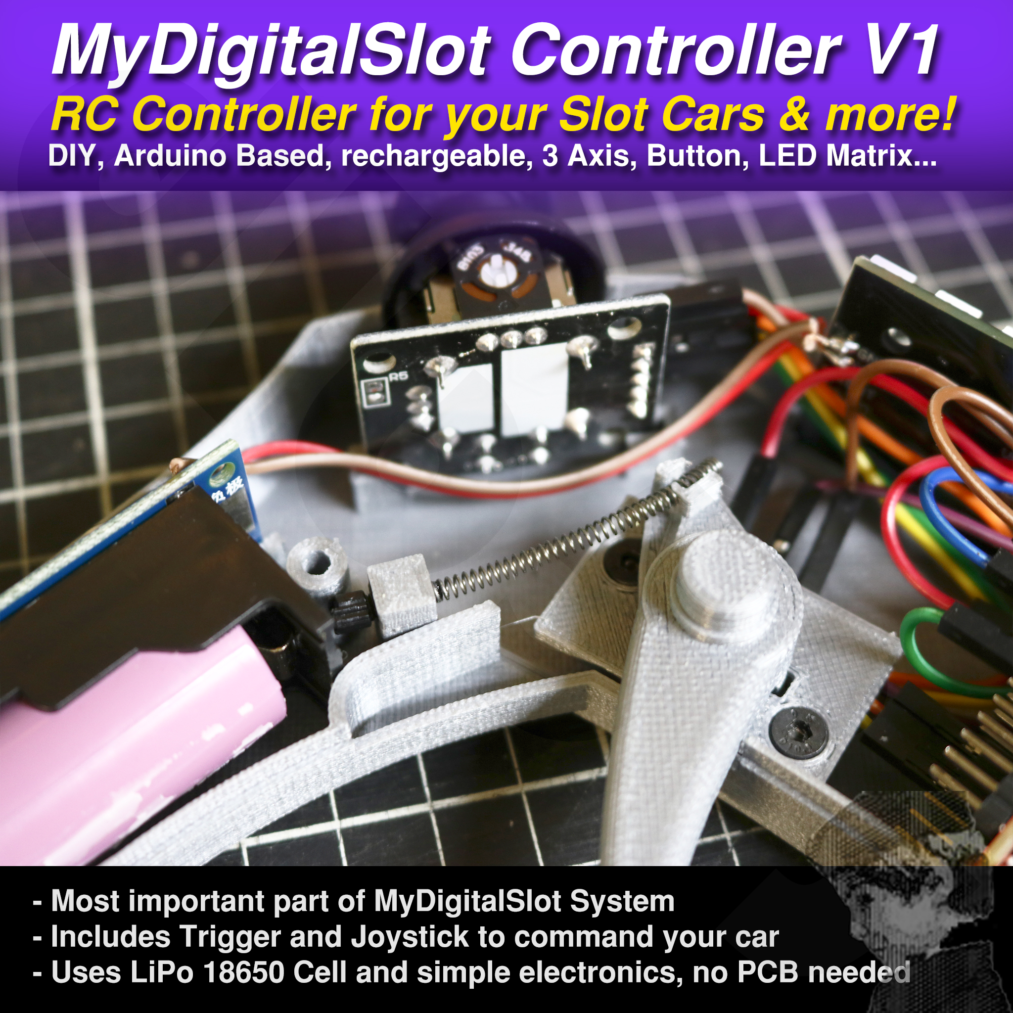
The parts to print are just a few, the both big sides, the trigger and the trigger holder. Every electronic component will stay in place once you join both 3D printed sides.
But there are a few cables in there! Let's see who is who and why are each one of them there.
The UPS LiPo Module is easy to understand. You charge it by Micro-USB, has an UPS output with GND and 5V and a place to add a switch to turn the output ON/OFF.
Four elements will need GND and 5V, those are the Arduino, the Joystick, the Potenciometer and the 4x4 LED Matrix.
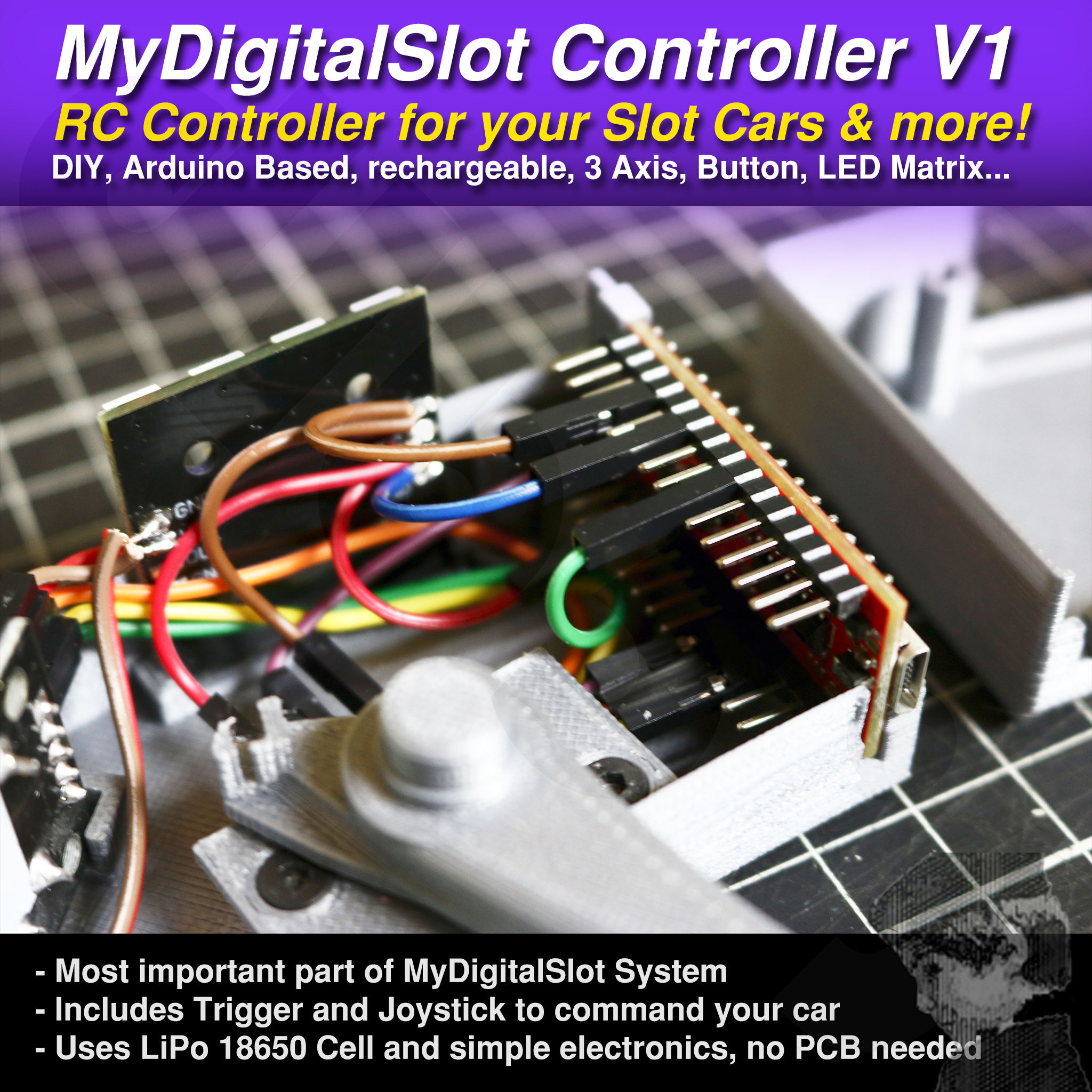
As you have to solder over the LED Matrix some cables and have four grounds and two VCC (5V), for me is the way I "distribute" the ground and 5V to each element. Please, see how I distribute and solder the cables in the pictures.
Once the power distribution is clear, you will notice some extra connections are needed, the "signals"... The joystick remaining pins will be X, Y and SW, the central Pin of the Pot will be its signal and the "IN" of the matrix will be its data input.
You can connect Joystick X Y and SW with 10cm Female-Female dupont cables to the arduino, the same than the Pot signal. I use half of this dupont cable to connect the Matrix IN to the arduino.
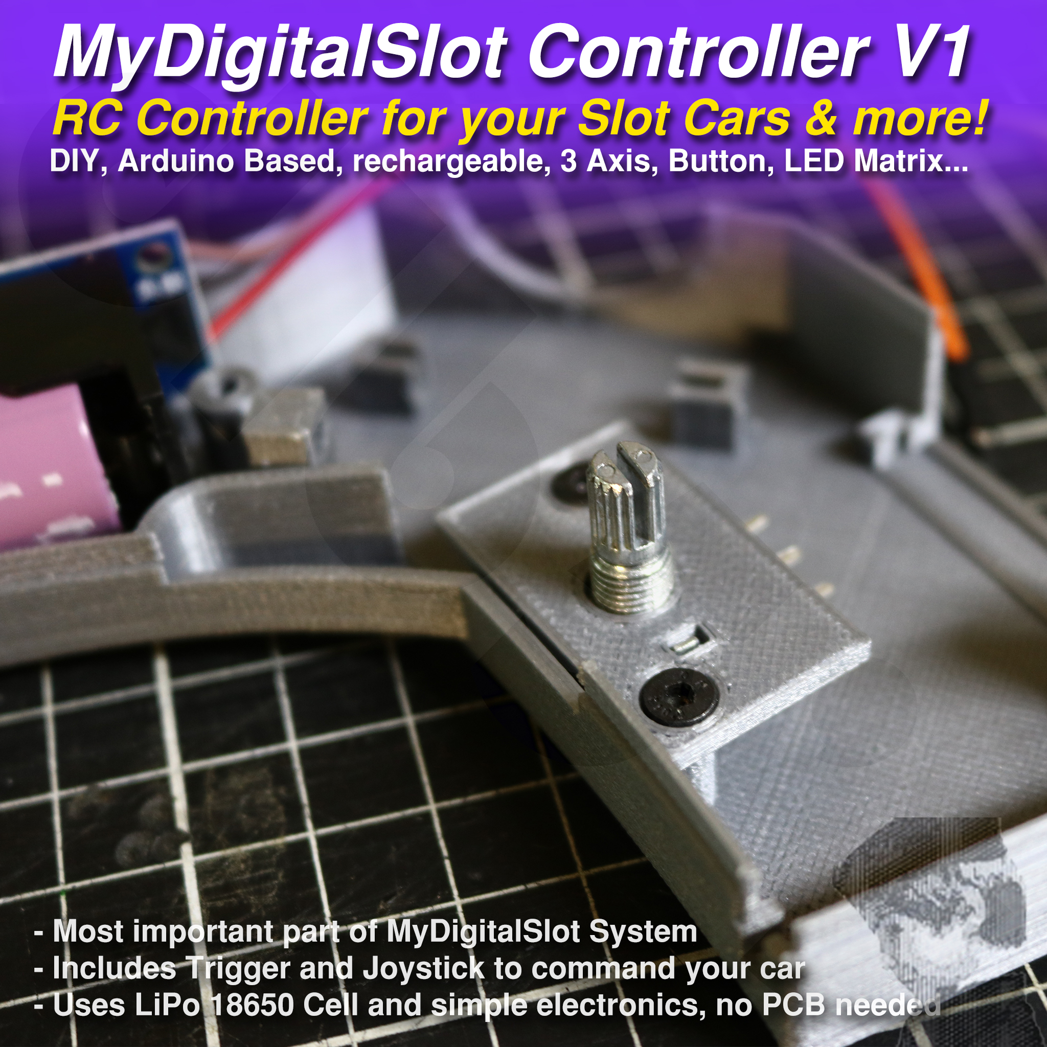
Use the left 3D printed side of the radio to assemble it. Start inserting the Pot into the "Trigger Holder" and screw it in place with the two M3x8 screws. Find the middle position of the Pot and then insert the trigger over it in the position it will be when not triggered. That way, the "IDLE position" of your throttle will be around 512 (half of total 1024).
Next try to dispose all the elements over the left part of the radio and, if you previously soldered your "Power distribution" cables you can really start the build.
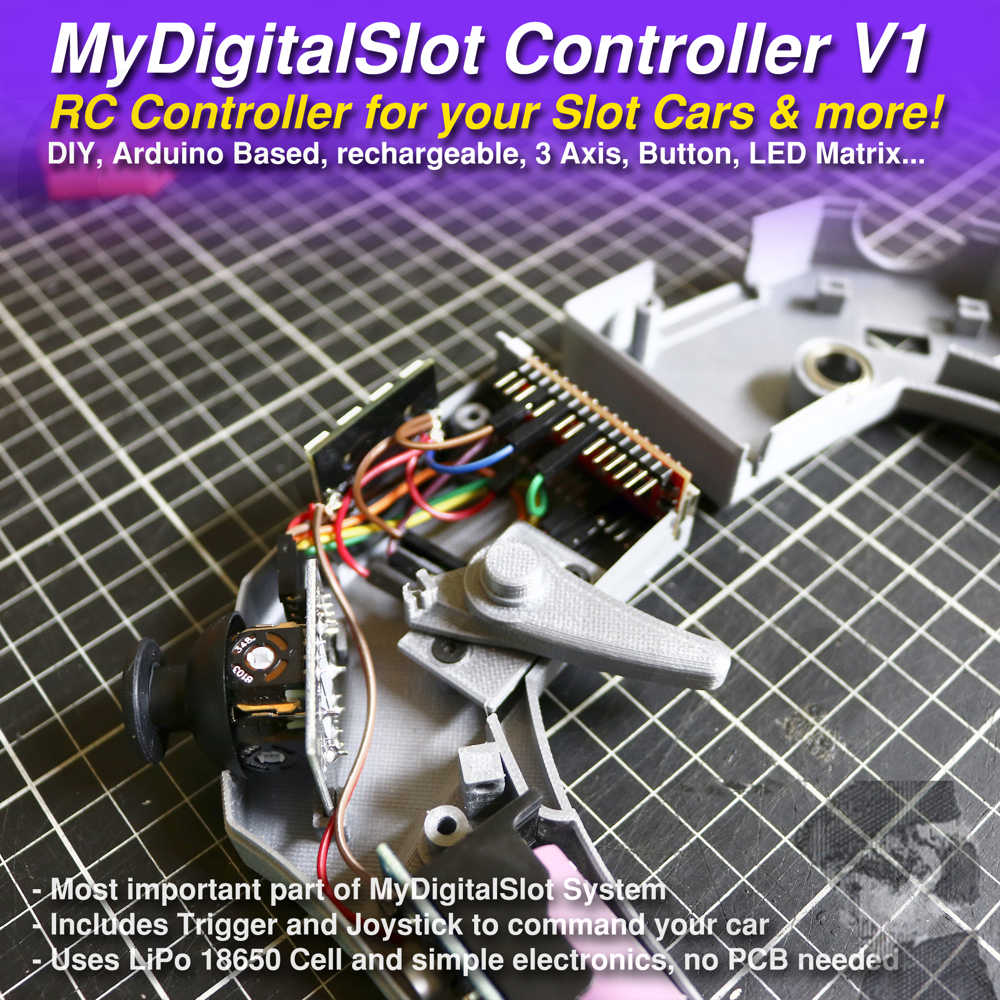
Add the X, Y and SW dupont cables to the Joystick and put it in place while trying to guide the cables to the "arduino's zone". Also add the dupont cable to the mid pin of the Potenciometer
Add the LED Matrix with all the power cables soldered to its place. Connect the very short GND and 5V duponts for the Joystick, half duponts for Pot (the ground is the one near the arduino) and the other pair of half duponts to Arduino 5V and GND.
You will probably need some kind of thin tip pliers or other way to put each dupont cable in place.
The connections with the arduino for the data cables are the next ones:
- Joystick X --> Arduino Pin A3
- Joystick Y --> Arduino Pin A5
- Joystick SW --> Arduino Pin 6
- Throttle Pin --> Arduino Pin A7
- LED Matrix IN--> Arduino Pin 3
That way you will be able to use the same code than me with minimal modification.
You will need to know your minimum and maximum throttle values and add them to the code until I program an "auto-throttle calibration" fuction or something like that.
Once you have all the elements connected, you could upload the code to the arduino and see if the "screen" starts flashing in orange, which would mean "no car connected".
If everything is OK, add the Clipper Spring, the bearing in the right side and maybe close the Controller adding the right side and screwing them together.
Remember to glue the clipper spring to its "plastic screw" with a little of ciano before assembling if you don't want to disassemble the controller soon.
Now that some things seems to work, with the Controller connected to the PC, open the Serial Monitor in the Arduino IDE and look for the minimum and maximum values when you move the throttle to its limits.
Add this numbers in the proper place at the begining of the code to enjoy your full throttle!!!
The value "thisPlayer" will be the one which represents the player number. Set it to 2, 3 or 4 if you are uploading the code to your second, third or fourth controller, and remember to adjust max and min throttle values for each controller build!
VERY IMPORTANT:
Once you have printed and built the controller, you will need to upload some photos of it to get access to the "MDS Basic Controller Code" for the arduino. If you don't want to do this, you will need to create your own code, as the code is not part of the product, the STLs are.
Once you have my code, you will be able to modify it to your needs or improve it a lot, add new features if you want... but buying this product you accept you will not share that code with others than the community I will try to create in my Discord Server. Those of you who want to give it a try to this "System" will be that community, and if you help me improve and test this system, I will go on sharing with you my code improvements and new features.
ACTUAL STATE OF THE CODE:
Hey, I'm just an individual in the basement and I have been working on this now for 10 months non-stop. I have reached what I think is a good start point, but the code is far away from being perfect or "profesional". I need feedback to improve it, I hope yours soon :) More than the code for the Controllers, there is other for the cars, another for the Info Screen and finally another one for the Lane-Changers if needed.
It could be easy adding new features in the near future like "Last Lap" times or "Best Lap" times, given the fast comm between car and controller, or programming an "Auto Pitlane" to put all cars in the pitlane or force some deviations... What about a ghost car?¿? Something like make the other cars move at a chosen speed... Sending a EMP to the other players?¿?
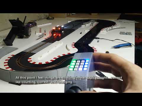
Anyway what you have seen in the videos is what you can actually expect, fuel and health bars with maxSpeed Caps, lapcount, pitlane, boxStop, Stop&Start, lane-changing plus the Race System between controllers.
Maybe you want it for your Long Board in the end, and want to use the Y axis of the Joystick as brake and you don't need the code at all...
Thank you for your time!