Skip to content

50 watt COB LED wafer cover

Advertising
Advertising
?
Creation quality: 5.0/5 (1 vote)
Evaluation of members on the printability, utility, level of detail, etc.

  • 317 views
  • 1 like
  • 5 downloads

License
3D design format
Folder details Close
  • 50W_COB_LED.stl
  • 50W_COB_LED_shield.stl

Learn more about the formats

Publication date 2023-01-05 at 06:54
?
Published to Thingiverse on: 2020-01-21 at 05:06
Design number 994417

3D printer file info

3D model description

https://www.aliexpress.com/item/32982350492.html?spm=a2g0s.9042311.0.0.52274c4dIAhxfq
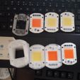
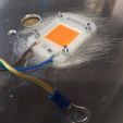
These COB LED units have direct mains input.
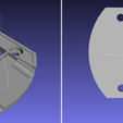
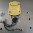
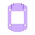
My cover is designed to protect against electric shock by covering the live electrical parts.
Be certain to solder carefully(I solder before attaching), run wires straight out and lay as flat as possible. I've seen some shocking soldering by people over the years. Here's my guidelines:
1. "Tin" the solder pads quickly with solder, you will see the surface change as the solder melts, you want to leave a shiny blob that is a nice smooth bump tapering down to the edges of the pad.
2. Strip no more than 4mm from the end of the Line and Nutral conductors, twist, apply solder between the iron and the copper, moving the solder to melt into the wetted out area of the twisted strands as it heats. Recheck you have no more then 4mm tinned, trim if necessary. There should still be a thin film of flux on the soldered strands.
3. Holding the cable straight and approx 30mm from the end, lay it on top and melt it into the blob on the COB LED. "L" is brown, "N" is blue in international wiring code for mains. Once the solder blobs fully merge, remove the iron while holding the wire absolutely still. if the wires are cooking your fingers you are too slow in your soldering technique, keep holding the wire straight and blow on the joint.

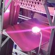
Fixing the COB: You need a BIG heatsink. Use the 3D cover as a drilling guide. Do an extra hole close by for earth wire WHICH MUST BE SECURELY ELECTRICALLY CONNECTED.

Use 12mm M3 screws or longer, push up through the heatsink, fit the COB with thermal paste over the screws and nut it tightly. Then push the 3D cover over the top and nut it on also. Note that you must nut the COB directly to the heatsink, not with the cover, overheating would soften the cover and lift the COB allowing more overheat.
Be sure to secure the mains cable to the heatsink so that strain does not wear at the connections.
Paint the heatsink black for better radiation cooling.

The second file has a little more of a pocket for the nuts so that the cover pushes back closer to the heatsink.

3D printing settings

-

Advertising


Issue with this design? Report a problem.

Would you like to support Cults?

You like Cults and you want to help us continue the adventure independently? Please note that we are a small team of 3 people, therefore it is very simple to support us to maintain the activity and create future developments. Here are 4 solutions accessible to all:

  • ADVERTISING: Disable your banner blocker (AdBlock, …) and click on our banner ads.

  • AFFILIATION: Make your purchases online by clicking on our affiliate links here Amazon.

  • DONATE: If you want, you can make a donation via Ko-Fi πŸ’œ.

  • WORD OF MOUTH: Invite your friends to come, discover the platform and the magnificent 3D files shared by the community!


Sharing and downloading on Cults3D guarantees that designs remain in makers community hands! And not in the hands of the 3D printing or software giants who own the competing platforms and exploit the designs for their own commercial interests.

Cults3D is an independent, self-financed site that is not accountable to any investor or brand. Almost all of the site's revenues are paid back to the platform's makers. The content published on the site serves only the interests of its authors and not those of 3D printer brands who also wish to control the 3D modeling market.

100% secure payment by credit card, PayPal, Apple Pay, Google Pay, etc.
View all payment options.