MyDigitalSlot Analog Track Controller
Maybe the name of this product is a little confusing… is it Digital or Analog? I hope you soon find it has the best of both worlds! It is a Digital way of controlling your Analog Slot Cars.
After developing all MyDigitalSlot System I realized that most of the people want to use their old track but more important, their analog car collection they made during years or decades… So having to print new cars and track parts for their “new digital hobby” didn’t make sense at all…
That is why I started struggling about how to satisfy those hobbyists with MDS technology. So I started thinking about how to use any track or cars with MyDigitalSlot… And that is how the ATC (Analog Track Controller) born.
THE CODE I use to make it work IS NOT PART OF THE PRODUCT. Please, read more at the end of the publication in “The Code” Chapter to know more about how to get the code
Main Characteristics
- Wireless and Rechargeable Controllers
- Lap Counting and Race System up to 4 players
- Race Configuration and Invitation System
- Fuel Consumption and Boxes
- Stop and Go for Race starts
- Start Lights in Controllers and Track Lights
- Start and Celebration Sounds in Track Controller
- Compatible with MDS Track Lighting and Info Screen
- Dual Pit Lane and Deviations compatible (in development)
This time, as I’m trying to reach every slot Hobbyist, I have tried to simplify as much as possible the design of the “Analog Track Controller”, and have made an extra effort to offer a compact version but also an “Easy to Build” version, which uses “Electronic Modules” instead of “Electronic Components”. This is the difference between having to build this with a lot of component soldering or just mostly using Dupont cables to connect the electronic modules.
I tried to accomplish this as much as possible for the Radio Controllers, but for this new “Analog Track Controller” you will need a soldering iron just for one or two points.
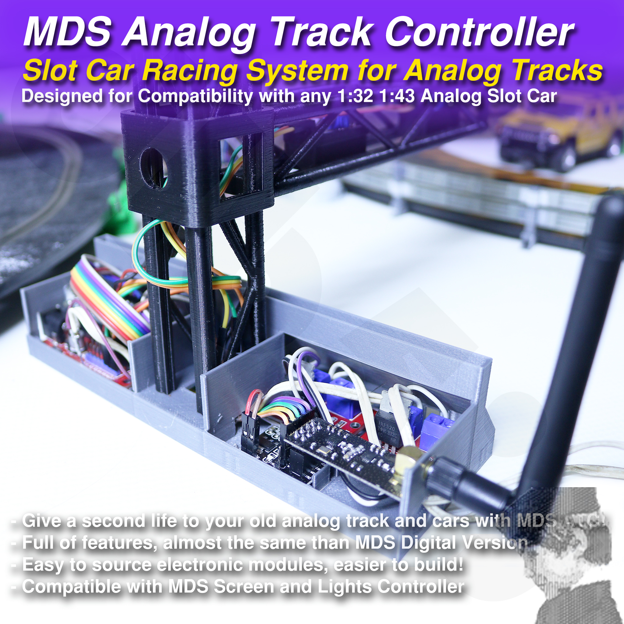
How the whole system works
I made this project after discovering how good Arduino + RF modules worked in my “RC Surface Radio” project.
As you probably know, MDS System (the Digital one) is also based in Arduino + RF for both the controllers and the cars. In this Analog version of the thing, the Arduino + RF remain in the Radio Controller, but instead of inside the cars, the receiver is in the “Analog Track Controller”.
Now the way you electrify your lanes is with Mosfet Modules from the Analog Track Controller, being able to control 2 lanes simultaneously with one ATC.
Infra-Red cheap modules over the track are responsible of detecting Laps but also Boxes when you stop under it.
A simple 5V buzzer can add some sounds to your races, with starting and winning sounds.
The communication between Radios and Analog Track Controller is bi-directional, that is how all the magic (coding) works, but also between radios and other devices like the “Track Lighting and Info Screen” one.
Building the system
As a good starting point, you will need two MDS Controllers and the ATC (Analog Track Controller). Printing the STLs for these parts is quite easy, compared with sourcing all the needed electronics and components for the system.
If you want to source parts for the Radio Controllers and build them you will have to take a deep look to the “MDS Controller” publication. For the ATC please go on reading.
You can build the “Compact” ATC or the “Easy” one, being this last one the one I recommend to begin.
The Easy Analog Track Controller
Sourced Parts Needed for “Easy” ATC
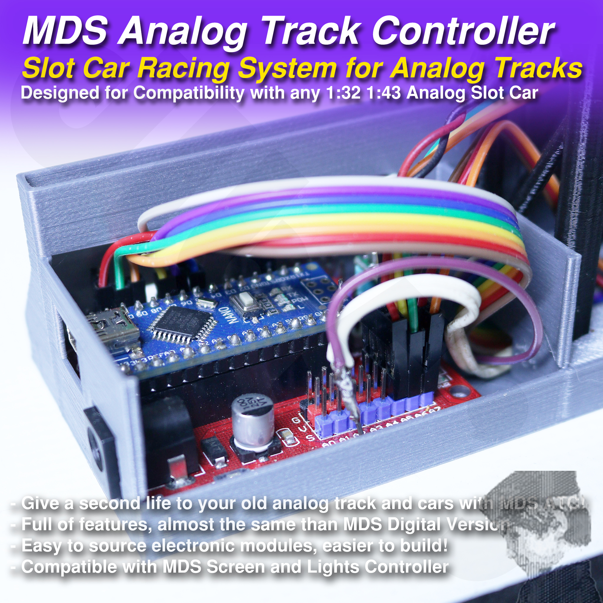
If you want to make it even easier, you can use an Arduino Nano-RF which includes the NRF24L01 module and will avoid connecting 7 cables between the Arduino and the RF antenna. It is also the one you need for the compact version.
The DC-DC module is mandatory if you don’t want to burn your Arduino. Why not powering the Arduino naturally by the Vin Pin, as the Shield is intended to do? Because you will connect 2 IR modules plus 2 Mosfet Modules to the Arduino at 5V, and the 5V are converted from Vin Voltage by the Arduino with a little converter which gets really hot and make the whole system instable.
On the other hand, using the little DC-DC module will allow us to do much more over the 5V rail and the Arduino won’t get as hot, but also will allow us to use more than 12V input power, which would be a requirement for some analog cars and tracks.
Making the Connections
The Nano Shield will help a lot as a breakout board and will allow us to connect most of modules really easy, for example you will be able to connect each IR module with 3 long Dupont F-F cables, GND, 5V and Signal, while you will only need two F-F ones for GND and Signal for the Mosfet modules.
As I said before, to connect the NRF24L01 Adaptor Module to the Arduino you will need seven F-F Dupont cables and the connections will be as follows:
- Arduino D10 Pin -> Adaptor CE Pin
- Arduino D9 Pin -> Adaptor CSN Pin
- Arduino D13 Pin -> Adaptor SCK Pin
- Arduino D11 Pin -> Adaptor MOSI Pin
- Arduino D12 Pin -> Adaptor MISO Pin
- Arduino GND Pin -> Adaptor GND
- Arduino 5V Pin -> Adaptor VCC
You can take the GND and 5V from many places in the board; I took them near the D13 connector.
If you want to use my code “as it is”, you will need to connect the Mosfet Signals to D5 and D6 pins, while you will have to connect the IR Modules Signals to A6 and A7 pins.
So the IR modules, the Mosfet ones and the RF adaptor can be all connected to the Arduino using F-F Dupont cables; That is the “Easy” part of the electronics. But as I said before, you will have to make a pair of soldering operations to fully have it going.
As a first point you will have to NOT supply the Arduino with the “Vin” DC power. For that, I used a very simple trick: MOVE UP the Vin Pin in the Arduino, so it doesn’t connect to the socket under it.
For that, I simply heat up the pin and push it up. How? Make pressure on the bottom of the pin, pushing that pin against a surface which doesn’t touch the other pins, while heating up with the iron. That way, when the tin is liquid the rest of the Arduino goes down and the pin comes up and you can stop heating. You should be able to undo this operation very easily.
You can also do this alternatively interrupting the Vin Trace in the board, but I think the other way is more convenient.
The second point is related to the DC-DC converter and the main power for the Mosfets. You must supply them with “Vin” and you can take it from two places, the back of the Black DC Connector, where could be +12-15V depending on your DC Adaptor, or the “Vin” mini hole you will find in the board, which is protected behind a diode, which will give you a max of 11.3V for 12V input.
So you will have to provide with Vin to the Mosfets and to the DC-DC converter. How I did it?
I took regular 2 wire cable and cut a piece, joining both wires in one extreme, while supplying the Vin to both Mosfets with the other extreme. I also joined a cut Dupont female cable to the first extreme of the previous cable, long enough to reach the DC-DC converter, and soldered this extreme of the cable to the little “Vin” hole in the Arduino Shield board.
The chosen DC-DC converter has 3 pins we need to use, the Vout, GND and Vin. We want the Vout to be 5V, and for that you will need to make some adjustments in the back of the module.
You can use the potentiometer in the board to adjust your Vout to 5V, or you can interrupt the “adjustable” trace in the back of the module and solder the 5V pads to be sure of having 5V Vout.
How and where to install the DC-DC module?
I solder two female 2.54 sockets under the Vout and GND pins, which will be connected to the Shield in a particular position, the 5V and GND pins near the TX RX ones.
For the Vin, I solder a male 2.54 socket, so I can plug it in the Dupont Female cable coming from the Vin. You will need to bend a little the male socket to really accommodate everything in its final place.
Alternatively, you can solder two cut female Dupont cables for 5V and GND, and another Male cut one for the Vin. If you have to solder yes or yes, I think the other option is better.
The Compact Analog Track Controller
Sourced Parts Needed for “Compact” ATC
- Arduino NANO-RF
- 2x IRF520 Mosfets
- 2x 1K resistors
- 4x DO-41 1A 40V SCHOTTKY 1N5819 or similar
- 20x17 0.1” 2.54mm pre-perforated PCB
- 2.54mm female sockets or cut Dupont female
- 2.54mm male sockets or cut Dupont male
- 2x PCB Connectors
- 2x TCRT5000 “blue” Infrared Modules
- DC-DC 5V3A Step-Down Regulator
- 2 wire cable for “Power IN” and “lane1” and “lane2” outputs
- 12-15V ACDC approx. 2A Adapter with standard connector or your slot one
Making the Connections
This one won’t be as “easy”, but its footprint will be half than the easy one. It hasn’t been finished at all so your electronics will remain exposed but attached to the holder.
You will need to build the thing up on a pre-perforated PCB with 20 columns and 17 rows. You will need to cut the board at exactly 50.8mm x 43.18mm, the space occupied by the holes.
Start building a Diode Bridge with the four 1N5819 to avoid reverse-powering the thing. You will get a GND and V+ Output from V1 and V2 inputs, so doesn’t matter if V1 or V2 is the ground or the V+.
You will need to share the ground with the DC-DC Module, the Arduino, Mosfets, and the Male Dupont sockets for IR Modules and Servos.
You will need to share the V+ with the DC-DC Module and the PCB Connectors, but also connect the other Pins of PCB Connectors to the Mosfets.
Use the Vout of the DC-DC Module to get 5V and share them with the Arduino and the Male Dupont Sockets.
Connect the signals of the Arduino with the Mosfets, using a 1k resistor in parallel with Ground. Also connect the Analog signals A0 to A7 to the Female Dupont sockets, or the ones you are going to use, minimum 3 if possible.
Solder a 2 wire cable with the connector of your choice to the V1 and V2 inputs and connect the output cables for the 2 lanes to the PCB Connectors.
If you are wondering how I did most of these connections, I just used the component’s “legs” of resistors and Mosfets, but also copper wire from a RJ-45 cable.
Very important, avoid powering the Arduino with the Vin Pin; use the 5V coming from the DC-DC module instead.
Required Knowledge
As you can imagine, this project goes beyond 3D printing, in fact is more about electronics than 3D printing. You could examine this publication and just do your own controller with the same electronics, but I hope you prefer to save some time using the parts I created to mount the electronics, the same than the code I wrote to make it work.
- Arduino IDE is the key for me to modify and upload the “firmware” to the radios or the controller. You must know how to select the right board, port, and the basic procedure to upload the firmware… check->upload
- Basic electronics knowledge will be also needed to understand what you are doing but also to review each of the steps, connections or modifications to the code.
- Improvisation, only if you don’t find exactly the same electronic parts or something doesn’t fit at all
- Soldering and de-soldering, especially for the “compact” version
- Troubleshooting is the final key. It will work if you get to the point I did, but you will always want it to perform better, so get ready ;)
Required Tools
- As you probably know, I tried to reduce the number of tools needed but I couldn’t make a version which completely avoids using a soldering iron. Try to get one thin enough for electronics, the same than some soldering tin.
- If you want to de-solder the Mosfets from their modules to use them in the Compact version, you will also need a “de-soldering tool” or a lot of patience
- Scissors to cut some cables and prepare them for soldering or connecting
- Multimeter, you will need it continuously to review each of the connections, specially the continuity mode, the 20V CC measuring mode and a few more modes
- A magnifying glass can help too to see if some of the soldering points are correct, identify some component naming, etc.
- Isolating Tape can be useful in some cases but not needed per se
The Code
THE editable CODE is actually something I consider very personal and IS NOT PART OF THE PRODUCT. As I’m not a professional programmer, I did my best, especially about making it really work, but it must be full of things that could be done better.
Instead, you can use the pre-compiled code as a start point, which is included with the publication.
I have spent thousands of hours with the track parts, the car chassis or bodies, the hand or track controllers or the accessories. I mean the design of the printable parts! Those designs are related to the electronic parts used in most cases, so one thing depends on the other.
The fact is that I have spent the same or more time programming the code, trying different ways of communication with different libraries, different ways of controlling the motors with different electronics, different ways of sensing the laps or boxes and more.
That is why I consider the code more important than some printable plastics for the electronics, and that is why I will share the editable version with you once I can see with my own eyes you are really into MyDigitalSlot hobby.
You can of course use same electronics and write up your own code and probably you will do it better than me. For that, you will only need to download the STLs and use them with your code.
Anyway, remember to correctly give attribution for the 3D printed parts at less…
What I would like you to do is buy the MDS designs -> Build them -> Show them -> troubleshoot it a little -> Receive the editable code -> make your minor mods -> suggest improvements. The same way, if you consider a mayor mod could be interesting for some reasons, just share the idea to see if can be incorporated to the main code somehow.