Update 1/17/2017
By request, I've added a 7/16 rod and nut size as well. I've not updated the text below, but just download the files ending in 7-16 (7/16) instead of 1-2 (for 1/2).
Introduction
I created this to help level the wonderful MPCNC machine designed by Allted (Ryan). I wanted a simple way to accurately level the MPCNC to the table across all four corners, as well as to easily change the height when I want to work on different material sizes. As most MPCNC users know, the further the distance the milling surface is from from the XY conduit plane the less stiff the machine is. This design lets you easily change the height of the machine to keep it stiff, get it perfectly level to the workpiece, and even provide extra support on the XY conduit runs (if you have a large table, because the connection to the conduit fits between the roller bearings). It works on the original and the 525 version of the MPCNC.
Parts required
You will need to print four copies of each of these parts, one to be put near each leg. You also need four 1/2" threaded rods (sufficient length to according to your table legs, I use one foot rods) plus 12 1/2" matching nuts. I recommend four regular nuts, plus eight locking nuts (the design has been built to support either locking or regular). The locking nuts can be placed on each side of the crank to secure it in place. However, you can use all regular nuts and that has worked fine as well. To mount the bases to the table you will also need eight machine screws, washers and lock nuts (length will vary based on your table thickness, but I used #6-32 x 1.75" machine screws on my 3/4" MDF table). I got my rods, screws, washers and nuts from our local big-box hardware store (Lowes), all in-stock for under $15.
Installation
You will be extending the table legs below the surface of the table, and also adding new adjustment threaded rods next to those legs. Before starting, make sure your table design doesn't block your ability to make this work, since some tables may have support braces blocking where those leg and adjustment holes need to go.
You must also first have your corner legs penetrating the table top (so you can adjust the table height up/down to the full length of the legs). This requires that you drill a hole larger than your conduit at each of the four corners and then switch to a longer conduit run (I use about one foot per leg).
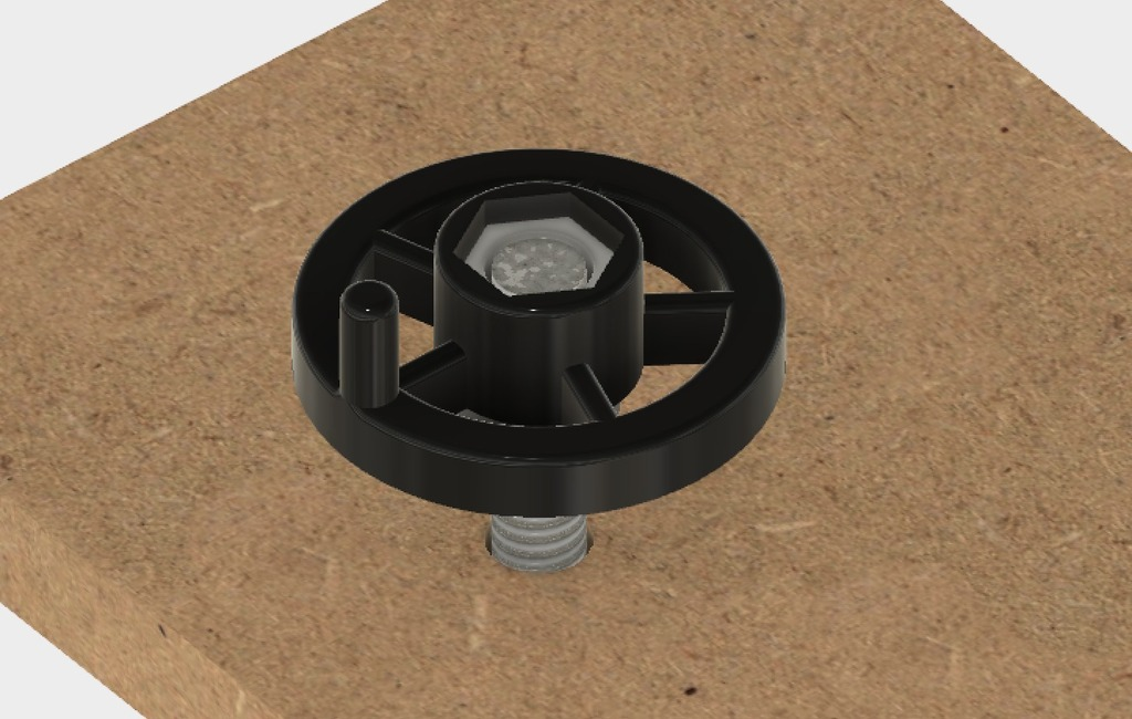
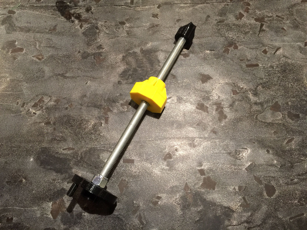
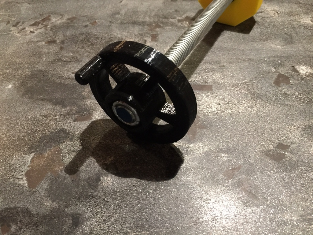
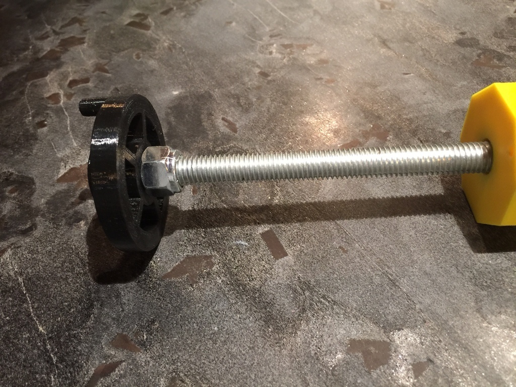
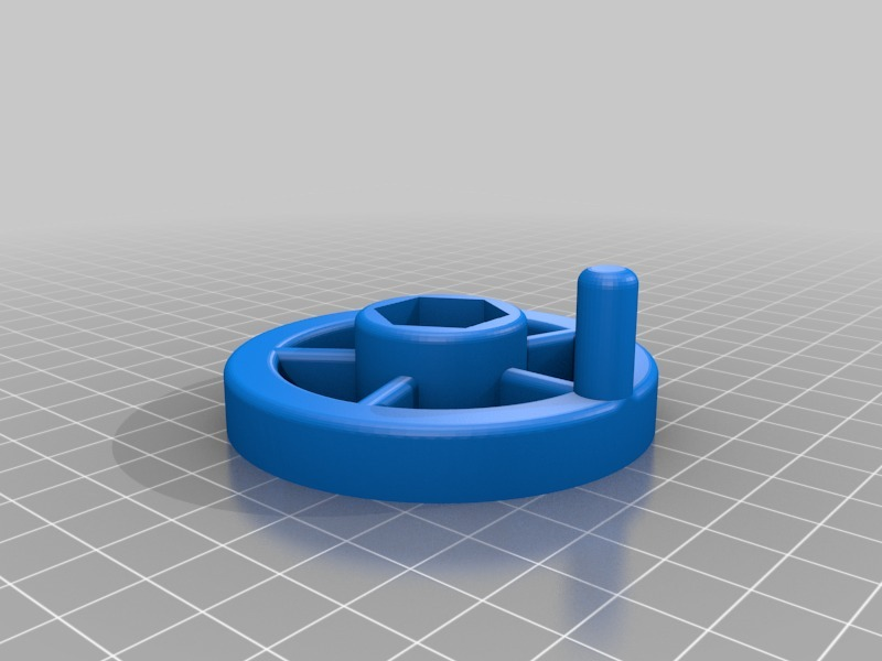
Start by assembling the threaded rod and crank assembly. If you are using lock nuts for the crank, you will find you will need to put on one end of the rod two regular nuts first and crank them tight against each other. This will then give you the leverage with a wrench to then install the other lock nuts. I like to have the flat ends of the lock nut resting against the crank, but it is difficult to thread a lock nut on "backwards", so I find it best to screw it on the "correct" way (flat part going on first, not the nylon end), then unscrew it, and put it back on the opposite way. With one lock nut on, put on the crank and a second lock nut, and tighten it down such that the crank is at the end of the rod. No need to over-tighten because the lock nuts will hold, but if not using lock nuts you will need to tight sufficiently to keep it from getting loose (you might even consider a lock washer instead).
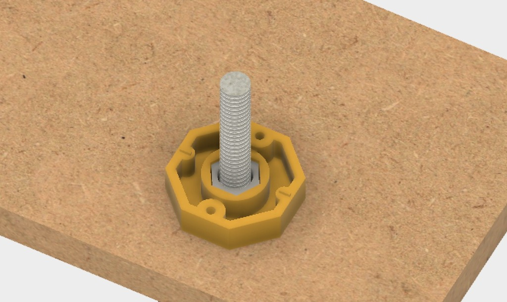
To install the levelers you will need to drill a hole in the table (best is slightly larger than the diameter of the threaded rod, I used 5/8 inch) aligned directly under the XY conduit runs near the corners. I recommend all four on either the X conduit or the Y conduit runs.
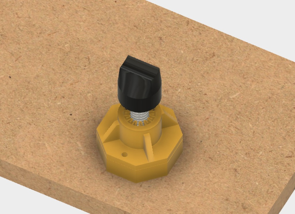
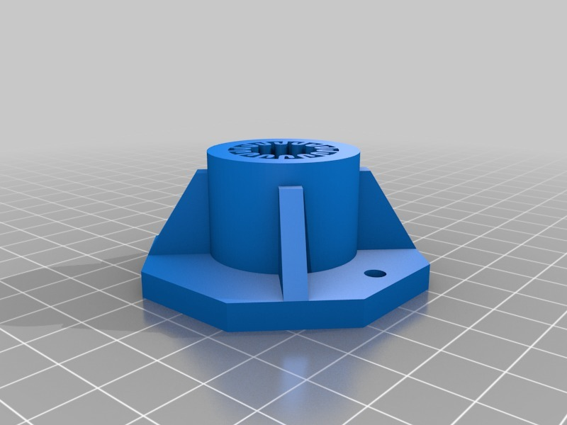
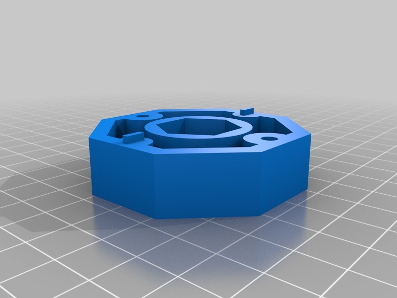
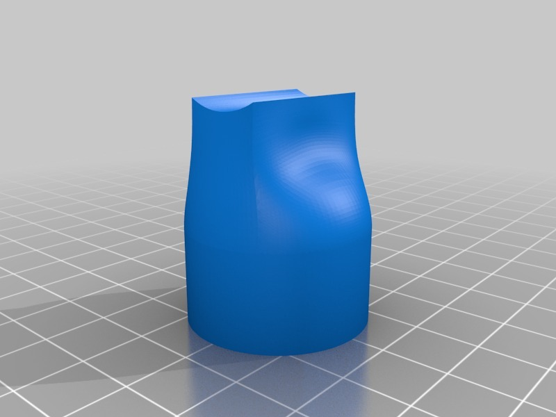
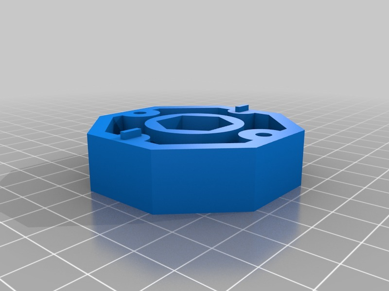
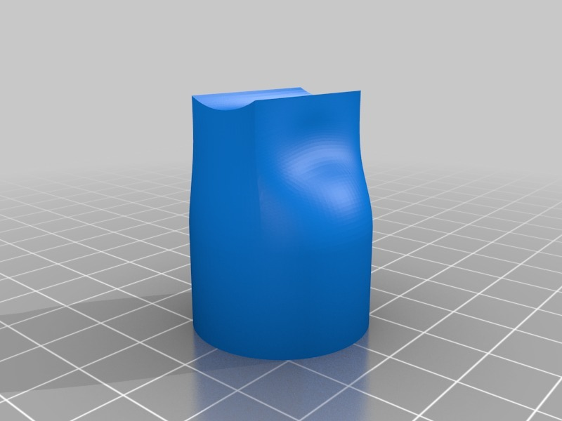
Insert the rod with crank from the bottom up the table, add a base, nut and bushing and finally the conduit holder. The rod will be sloppy until it connects with the conduit, then it will stiffen up. Once this is in place, adjust the base/bushing into final position and rotate to get access to the mounting holes, and drill the holes. Now mount your bolts (#6-32 x 1.75" is what I used), screws and lock nuts onto the base/bushing.
Usage
To use the levelers, start by raising the mill to the highest point where you are comfortable you won't lose the Z lock nut. Adjust the levelers so that the end mill clears the table, plus stock, plus whatever your working height clearance is (and ensure you have sufficient room somewhere to do end mill changes). Now use something such as a 1/2" piece of MDF, and place the mill at the four corners of the stock and adjust levelers to just clear the MDF. I modified my post code to move the mill to near the four corners of the stock at the stock of every run, to ensure I always level (which helps deal with minor board warping).
Need a different size?
I apologize in advance that I have only uploaded a 23.5 conduit with 1/2" threaded rod (and 1/2" is overkill, likely I could have gotten away with 3/8" or even 1/4"). The reason for this is simply because I don't know what size threaded rod should be used with the other conduit sizes. The design is fully parametric (using Fusion 360) so it is simple to adjust it to any size. If you would like a specific combination of sizes, please leave a comment and I'll be glad to upload another set. I'll need the following information:
* The outer diameter of the threaded rod (mine is 1/2")
* The thickness and width (flat section to flat section) of the hex nut (mine is .44" thick and .75" wide)
* If you wish to use a lock nut, I'll need the thickness of that as well (mine is .59")
Send this info on over, and I'll punch the values in and upload a new set of STL files. If only Thingiverse would support Fusion 360 parametric designs, then you could do it yourself...!
:format(webp)/https://fbi.cults3d.com/uploaders/27416719/illustration-file/26a6fca9-cda5-4f66-a202-08cf6b94d7c3/installed.jpg)


/https://preview3d-images.cults3d.com/mm5rv2it03xqd68mzt4y3wmnisid)
/https://preview3d-images.cults3d.com/js4cb8nr7v55ynkwn8wqa7qwsqkv)
/https://preview3d-images.cults3d.com/3n2q73he0kjlez1c5m3idt9y8z1t)
/https://preview3d-images.cults3d.com/l8r4dvh4w9tu896mrxdbk50lp37y)
/https://preview3d-images.cults3d.com/p7pijettmwqht9urceozj2aago1v)
/https://preview3d-images.cults3d.com/ed7arx3ynbspv1oz3lc4vfyoly5h)
/https://preview3d-images.cults3d.com/56dxbpelsquk1azmb7neh6fv1tg0)
/https://preview3d-images.cults3d.com/28cg49awg1hydo7nnmbb8rk73ey6)
