

Introduction: A Dodecahedron Speaker for Desktop Printers


At normal listening distances, an array of twelve speakers arranged on the faces of a dodecahedron is a very good approximation of a point sound source, and the sound waves it produces are very close to perfectly spherical. A dodecahedron speaker can be a useful tool in acoustics research, and is definitely a fun toy to pull out at parties. They are available commercially, but very expensive. Some people build their own, but the odd compound angles and the high degree of accuracy and precision required in the parts make for challenging work with manual tools. But it's easy for a 3D printer.
If you have a RepRap, MakerBot, Up!, MakerGear, Ultimaker, or other suitable fused-filament printer, you can print and build this speaker for just under $100 in parts and materials. That includes speakers, hardware, wires, cable, plastic filament--everything.
The high symmetry of the dodecahedron is amenable to a modular design, and this one consists of four basic parts: the face modules, the vertex plugs, the edge gaskets, and the bezels. (NOTE: These models are also available on Thingiverse.) The speaker grilles are made from hardware store window screen cloth installed in the bezels using rubber spline and a screen roller tool, just like a residential window screen.
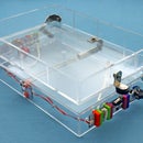
The assembled speaker array weighs 5.6 lbs, not counting the cable, and measures 7.5" across, from face to face, and 8.6" from point to point. The speakers are wired in a hybrid series-parallel circuit that brings the total array impedance to about 10 ohms (again not counting the cable) which should be a comfortable load for most amplifiers.
Non-printed parts ("vitamins")
12 pcs × speaker, square, ferrite 3", 8 Ohm, 3W, Jameco SP83W
10 ft × instrument patch cable, 18 AWG leads, such as Conquest Sound CS118
30 pcs × sex bolt (hehehe), combo truss head, zinc plated, 3/16" barrel, #6-32 × 3/8", Bolt Depot 14285
30 pcs × machine screw, combo truss head, zinc plated, #6-32 × 1/2", Bolt Depot 2887
60 pcs × split washer, #10, zinc plated, Bolt Depot 3023
108 pcs × wood screw, #4 × 1/4", black oxide or finish of your choice, such as McFeely's 0402-PSK
13 ft × screen spline, vinyl serrated, 1/8", black or color of your choice, such as Home Depot 3028737
3 sq ft × window screen, black or color of your choice, such as Home Depot 3003947
36 in × hook-up wire, stranded, 18AWG, white or color of your choice, such as NTE
18 in × hook-up wire, stranded, 18AWG, red or color of your choice, such as NTE
2 pcs × craft foam, adhesive-backed, 8.5 × 5.5" sheet, black or color of your choice, such as Fibre Craft
2 pcs × wire nut, orange, such as Ideal 73B
1 cu ft × glass wool, such as Owens Corning PINK
6 in × electrical tape
Tools
3D printer - I use and enthusiastically recommend the MakerGear Mosaic M1, but any RepRap-type fused-filament printer should work so long as it has a build volume of at least 122 × 122 × 14 mm. Mine is equipped with a 0.35 mm extruder nozzle and a heated build platform. I print onto a 1/8" aluminum plate covered in painter's masking tape. To make models (CAD), I use Google SketchUp Version 8 with D. Bur's su2stl plugin for STL import / export functions. To convert STL models to G-code machine instructions (CAM), I use Alessandro Ranellucci's Slic3r (v 0.7.1). To actually control the printer (client), I use kliment's Printrun. All of this is free software.
2D printer (laser or inkjet)
Multimeter & leads
Soldering iron
Small butane torch, such as Bonjour Chef's Torch (optional, for flame-polishing)
Wire strippers
Hole punch, 4.5 mm, such as Harbor Freight #97715 (optional, for punching holes in gaskets)
Scissors
Spring steel shim, such as iSesamo (optional, but handy for removing parts from build platform)
Hex driver with basic bit set
#0 square drive hex bit (required for McFeely's wood screws)
Additional Phillips-head screwdriver (you will need two screwdrivers for tightening sex bolts)
Needle nose pliers
Hobby knife
Wire cutters
Tweezers
Screen roller tool (such as Prime-Line #P 7503)
Sharpie permanent marker
1/8" metal rod, 6+ inches (optional, for holding plugs during flame-polishing)
Long-sleeved shirt (for handling glass wool)
Latex, nitrile, or other protective gloves (for handling glass wool)
Consumables
Plastic filament - My extruder takes 1.75 mm diameter filament, and I prefer to print in polylactic acid (PLA). Using my CAM settings, you will need 185 meters of filament which, at typical densities for 1.75 mm PLA, should weigh about 560 g. So a 1 kg spool should be plenty, if you only want to print in one color. If you're printing in multiple colors, you will need about 150 m / 450 g of filament to print the modules, 33 m / 100 g to print the bezels, and 3 m / 10 g to print the plugs. None of these filament estimates includes an allowance for misprints or other losses, and in my experience you will probably want to add about 10% to account for these. All my filament came from MakerGear.
1 pc × printable paper label, adhesive back, 8.5 × 11", 2 × half-page label each, such as Avery 8126
8 in × solder, 60/40 rosin core, such as Alpha Metals 13460
35 ft × painter's masking tape, 1.5", to cover build platform
Step 1: Prep the Cable


One end of your cable will connect to your amplifier or other audio source, and depending on that source, you may want to leave the 1/4" phono plug as is, remove it, or replace it with some other type of connector. The other end of your cable connects to the speaker and will need to have the plug removed and the cable leads exposed.
The easiest way to remove the plug is to just cut it off a short distance behind the ferrule with a pair of sharp scissors. Toss it in your spares box and desolder the inch or so of attached cable when and if you use it, later. If the waste bothers you, of course, you can go ahead and unscrew the ferrule, cut away the heat shrink tubing, and desolder the connections now.
Once the plug is gone, slit the rubber cable sheath with a hobby knife for an inch or so at the end. Try to cut between the wires, but don't worry too much if you nick one. Once it's cut, grab the two halves of the split sheath and "banana peel" it back three inches, or so, exposing as much of the wire pair as you need. If you nicked the wires while cutting through the sheath, snip the ends off far enough back to remove the damaged part(s). Once you've got two inches of good wire pair exposed, trim away the excess sheath bits.
Tie a strain-relief knot in the cable another two inches back, or so. This knot, which is much too wide to pass through the narrow opening where the cable will exit the cabinet, will bear the weight of the hanging speaker.
Finally, strip about 3/4" of the insulation from each of the wires, exposing the copper strands.
Step 2: Print the Plugs


This is the smallest of the three printed parts. It measures 10 × 10 × 9.6 mm and, if printed individually, takes about six minutes to extrude. In PLA, each one weighs about 370 mg and uses about 125 mm of 1.75 mm diameter filament. I printed mine in black.
You'll need nineteen of them, one for each of a dodecahedron's twenty vertices, less one vertex that'll be occupied by the speaker cable. They are pushed into place after the cabinet is assembled, and are designed to flex as needed to seal and protect the dodecahedron's vertices, and to compensate for and conceal any small printing errors that might otherwise be obvious where three face modules come together in a corner.
I recommend printing all nineteen at once using the supplied "cookie sheet" model. If you prefer to print them individually or need to print spares, a single plug model is also available. (NOTE: These models are also available on Thingiverse.)
Before printing, you will need to "slice" the .STL model using Slic3r or another CAM program. This step turns the 3D model into specific mechanical instructions, in G-code, that the printer can understand. The settings you use to slice the models will vary with your particular equipment, but in my experience, the critical settings in Slic3r are as follows:
In the "Printer and Filament" tab, set "Nozzle diameter" to 0.35 (check your equipment to verify); "Print center" to 65, 65; filament "Diameter" to 1.75; and filament "Temperature" to 185.
In the "Print Settings" tab, set "Layer height (mm)" to 0.3.
My printer is not equipped with limit switches, and has to be manually "homed" before each print. If yours is similar, you may also want to replace the default "Start GCODE" with "G92 X0 Y0 Z0 E0". This tells the printer that, at the start of the job, all the motors will already be in their "home" positions. Also, replacing the default "End GCODE" with the lines "G00 X0 Y100", "M104 S0", "M140 S0", and "M84" will tell the printer, when the job is over, to move the hot nozzle away from the printed object, turn off the extruder and bed heaters, and deactivate all the stepper motors, respectively. All of which are useful and convenient.
For your reference, I have also attached the verbatim text of the Slic3r config file used to print all the parts in my dodecahedron speaker at the bottom of this step. If you want to use my settings exactly, you should be able to paste this information into a text editor, save it as a .INI file, and load it directly into Slic3r using the "Load config..." button before actually slicing the models. (Note that this may not yield satisfactory results unless your printer is essentially identical to mine.)
Once the model is sliced, open your printer interface and load the .gcode file output by Slic3r. Set the nozzle and bed heaters to 185 and 60 C, respectively, and give them about 10 minutes to warm up. Then prime the nozzle by extruding filament until a nice even bead squirts out. Pluck off this scrap with tweezers, home the nozzle, and click "Print."
Printing the group of all nineteen plugs took about an hour and a half on my equipment. They pop off the build platform easily.
Clean up any flyaway plastic strands on the printed models with a hobby knife. Or, if you're feeling brave, you can experiment with "flame polishing," which is faster but requires getting over the instinctive horror of holding a flame to your precision-printed plastic parts. For small parts, like these plugs, you'll need to mount them on a holder (a 1/8" metal rod works great). Then you just play the flame of a small torch over the surface very quickly and take it away. It requires, literally, a fraction of a second. This treatment neatly burns away any flyaways or flash while leaving large features of the part undamaged. And once you get the hang of it, it's much more fun than scraping with a knife.
===PLA.ini===
bottom_layer_speed_ratio = 0.3
bridge_flow_ratio = 1
bridge_speed = 30
duplicate_distance = 6
duplicate_x = 1
duplicate_y = 1
end_gcode = M84 ; disable motors\nG00 X0 Y100 ; home X and Y axes, leave Z alone\nM104 S0 ; Set bed and extruder temp to 0 (turn off?)\nM140 S0 ;
extrusion_axis = E
extrusion_multiplier = 1
extrusion_width_ratio = 0
filament_diameter = 1.75
fill_angle = 45
fill_density = 0.4
fill_pattern = rectilinear
first_layer_height_ratio = 1
g0 = 0
gcode_arcs = 0
gcode_comments = 0
infill_every_layers = 1
infill_speed = 60
layer_height = 0.3
nozzle_diameter = 0.35
perimeter_speed = 30
perimeters = 3
print_center = 65,65
retract_before_travel = 2
retract_length = 1
retract_lift = 0
retract_restart_extra = 0
retract_speed = 30
rotate = 90
scale = 1
skirt_distance = 3
skirt_height = 1
skirts = 2
small_perimeter_speed = 10
solid_fill_pattern = rectilinear
solid_infill_speed = 40
solid_layers = 3
start_gcode = G92 X0 Y0 Z0 E0
temperature = 185
travel_speed = 130
use_relative_e_distances = 0
z_offset = 0
Step 3: Cut the Gaskets


These are cut from ~2mm "fun" or "craft" foam, which is widely available at chain hobby stores. I used black to match my color scheme, but it comes in many colors and you should have no problem finding one to suit your own taste. You'll need 30 of them, one for each edge of a dodecahedron.
NOTE: This foam cuts cleanly in a laser cutter, so if you have access to one you can skip the directions below and just cut the foam directly from the supplied vector art. I did not, however, and used this paper template method with good results.
Print the gasket vector art on your 2D laser or inkjet printer. I recommend printing onto a sheet of two half-page 5.5 × 8.5" adhesive-backed mailing labels, because these nicely match the common size of the craft foam sheets that we'll be applying them to.
Peel the backing off the printed templates and apply them to the backing side of the craft foam sheets. Smooth them down evenly, avoiding wrinkles, and then cut the foam along the template guidelines into long "strips" of three gaskets each using a hobby knife and a straightedge Once you have ten strips, switch to scissors and snip out each individual gasket.
The last step is cutting out the holes where the bolts will pass through. I used the 4.5 mm head on my Harbor Freight leather punch, but in fact these edges are not visible in the assembled speaker and don't have to be "neat." If you'd rather just snip a triangle out of the bottom edge of each gasket with scissors, that would probably work fine, too.
Step 4: Print the Bezels


You will need twelve of these, one for each face of a dodecahedron. Each measures 121 ×121 × 4.5 mm, and most printers will only be able to handle one at a time. In 1.75 mm PLA, using my equipment and settings, each consumes about 2.8 m / 8.5 g of filament and takes about 45 minutes to extrude. I printed mine in black.
Slice the STL model and print as in step 2. (NOTE: This model is also available on Thingiverse.)
These are harder to remove from the build platform than the plugs. I found it easier if I let the build platform cool to room temperature, first. A flat metal shim, like the "spudger" shown in the photo, is extremely helpful for popping them off the build surface. Once you get a corner free, the rest of it should come up pretty easily.
Clean up flyaway strands of plastic with a hobby knife or by flame-polishing, as before. Be especially careful to trim any flash from the inside of the spline groove on the underside of the bezel, as the spline is designed to fit very closely in this groove and a bit of flash around the lip can make installing the screens much harder than it has to be.
Step 5: Install the Screens


If you've ever replaced a residential window screen or otherwise used a spline roller tool, this process will be familiar to you. If not, don't worry: It isn't hard.
Using scissors, first cut out one 6" square piece of window screen for each bezel (12 total). I chose the black (or "charcoal") screen to go with my color scheme (and because I had a roll of it on hand) but it comes in other colors and materials. I used fiberglass, again because I had it on hand, but aluminum screen is also widely available and could look really cool with the right color scheme. There's even a "fancy" variety available in a gold/bronze color.
To install one screen, first turn a bezel upside-down on your work surface, with the groove facing up, and lay a square of window screen over it, centered.
Like me, your first instinct may be to use a single continuous length of spline all the way around the circumference of the groove. After much experimentation, I have found that this approach makes things harder than necessary. If you try to make a continuous, complete circle, it is much harder to get the screen tension even around the bezel, and its easy to end up with an annoying wrinkle at the close of the circle that cannot be repaired short of starting over.
Instead, I recommend installing the spline in a number of short (~3/4") segments, working in a criss-cross "star" fashion across the diameter of the bezel, as if tightening a drum head. The installation won't be as pretty, but it scarcely matters because the spline is not visible in the assembled array, anyway. And this method makes it much easier to evenly tension the screen and avoid annoying wrinkles
To install a segment, first use the convex roller on your spline tool to mush the screen down into the groove over about a 3 cm distances near one corner of the bezel. Don't be timid about it. You're unlikely to damage the screen or the bezel, though it may feel that way at first.
Then, position a segment of spline in the groove and switch to the concave roller on the tool to push it down into the groove on top of the screen. Again, don't be afraid to put some muscle into it.
When the spline segment is firmly seated in the groove, jump across the diameter of the bezel, as if drawing a five-pointed star, and do the same thing on the opposite side. Work all the way around the circle in this criss-cross fashion, cutting smaller pieces of spline as needed, until the groove is 95% filled or more.
Once the spline is firmly seated, use a sharp hobby knife to trim away the excess screen, all the way around, close to the outside edge of the groove.
Repeat this step with the remaining eleven bezels.
Step 6: Wire the Speakers


Cut the following numbers and lengths of wire jumpers:
3 × 6", "red"
3 × 6", "white"
9 × 2", "white"
The wires are not visible in the finished array, so you can use whatever colors are handy. But sticking to just two will make it easier to keep track of the connections during final assembly.
Strip about 3/4" of the insulation off each end of each wire. Twist and tin the exposed copper strands. Bend each tinned lead into a short "hook" using a pair of small pliers, and attach the jumpers to the speakers mechanically, first, by putting the hooked leads through the holes in the speaker solder terminals, then closing the hook by squeezing gently with pliers.
First, attach a long white jumper to the negative terminal of each of three speakers. Then attach a short white jumper to the negative terminal of each of the remaining nine speakers. Finally, choose three speakers with a short white jumper already attached and add a long red jumper on the positive terminal. If you're confused, check the first photograph in this step.
When you're sure everything's in the right place, solder the connections.
Step 7: Print the Face Modules


The face module is the largest of the three types of printed parts. It measures 122 ×122 ×14 mm and takes about 2.5 hours to extrude. In PLA, each one weighs about 37 g and uses about 12.4 m of 1.75 mm diameter filament. I printed mine in orange.
You will need twelve of these, one for each speaker. Geometrically, the face module is a short section of a pentagonal cone with recesses for the speaker, the speaker mounting screws, the bezel mounting screws, and the bolts that attach it to neighboring modules. The boltholes have a "teardrop" shape so that they can be printed without support material. Each corner of the pentagon has been scooped out in a small semicircle, so that any three adjacent modules come together to form a cylindrical hollow where they meet. This feature allows for passage of a signal cable from inside the cabinet, blunts what might otherwise be hazardous or wear-prone sharp points on the assembled cabinet, and greatly simplifies the problem of getting an airtight seal at the vertices.
If you want to print the speaker body in a different color, change the plastic in your printer now. Slice the STL model and print as before. (NOTE: This model is also available on Thingiverse.)
After the first module comes off the printer, clean up any flash, flyaways, or other surface imperfections with a sharp hobby knife and/or a flame, then check the fit against one of your speakers. The cone should fit into the central recess cleanly, and you should be able to rotate the speaker such that the four mounting holes in the underside of the module align with the four mounting holes in the speaker flange. If the speaker fits, print the remaining eleven modules as above. Take a minute to check each module against a speaker right after it's printed, in case something goes wonky with your printer between the first print and the last.
Step 8: Mount the Speakers


With respect to the speaker's terminals, there are four different ways its can be mounted on the five-sided face module. When all the mounting holes are lined up, only one edge of the speaker flange will be parallel to an edge of the face module. The speaker's terminals should be on this edge. See the photo if you are confused.
Turn one of the face modules face down on your work surface. Choose one of your prepared speakers (it doesn't matter which), and set it in place with the speaker cone inside the large round opening and the flange flat against the module's back. Rotate the speaker in place until the terminals are on the correct side of the module and the mounting holes in the flange are aligned with the mounting holes in the module.
Pass a #4 × 1/4" wood screw through each opening in the flange and start it a couple of turns into the corresponding mounting hole in the plastic. Once all four screws are started, come back and tighten them all down. The speaker should be secure with no rattle, but don't overtighten the screws or you risk stripping out the plastic.
Repeat this step with the remaining eleven speakers and modules. Again, the modules are identical, so it doesn't matter which speaker goes in which module.
Step 9: Build Three Clusters of Four


The physical assembly of the array corresponds to the structure of the speaker circuit. Three "clusters" of four mounted speakers are first assembled together, with the four speakers of each cluster wired in series. In the next step, these clusters will be wired together in parallel to complete the circuit, and physically bolted together to close the dodecahedron.
To build a "cluster," first arrange four speaker modules face-down on your work surface, as shown. Each cluster contains
one speaker with a long red jumper and a short white jumper,
two speakers with short white jumpers, and
one speaker with a long white jumper.
Note, from the photo, the correct order of these four speakers, as well as the correct orientations of the speaker terminals with respect to each other.
You will be bolting the four modules in the cluster together along their five shared "inner" edges. Two modules are joined at each edge by a "mating pair" of male and female bolts and a pair of split washers (one under the male bolt head and one under the female bolt head). These are "lock" washers; when compressed, they provide constant tension against the threads of the bolts to prevent them vibrating loose over time.
Apply a gasket to one of the two trapezoidal faces along each "inner" edge. It doesn't matter which of the two faces gets the gasket, but if you're confused just copy the photos and it'll work out fine.
To apply a gasket, simply peel off the craft foam adhesive backing (which should take the template remnant with it), line up the edges of the gasket with the edges of the module, and press it into place with your thumb. Don't worry too much if the alignment isn't perfect. When everything's put together, only the long edges of the gaskets will be visible, and these will be trimmed flush during final assembly. In fact, it's better to err on the side of hanging too much gasket off the long edge than to have the opposite problem.
Now, press-fit a female bolt into the counterbore opposite each gasket. The bolt holes and counterbores are designed to be tight-fitting, so these bolts shouldn't need any help staying in place. If they do tend to fall out, though, it's not a big deal--it'll just make getting everything lined up during the bolting operation a bit trickier.
Now, proceeding as shown in the photos, work your way around the cluster, soldering and bolting each pair of speakers together before moving on to the next. In each case, you will be soldering the pre-installed lead from the (-) terminal of one speaker to the free (+) terminal of the next. As before, first hook the bent, tinned lead through the hole in the speaker terminal solder tab, then gently squeeze the hook closed with a small pair of pliers, before actually applying the iron.
Once the connection is soldered, bolt the corresponding edge or edges together. Don't tighten the bolts very much at this point. Make sure the threads are engaged, but the split washers should not be compressed much. A good rule of thumb is to only use one screwdriver, for the moment, tighten from one side only, and stop turning once the opposite bolt head begins to spin. The bolts will not be tightened "all the way" until the array is fully assembled.
Once you have a cluster of four modules soldered and bolted together as shown, get out your multimeter and test the series resistance across the red and white leads. It should be about 30 ohms. If there's a bad connection or component, now is the time to find out about it.
Finally, work your way around the circumference of the cluster, applying gaskets to every other edge. It doesn't matter which edge you start with, but make sure it's the same one, relative to the red lead, on each of the three clusters. Then go back, as before, and press-fit a female bolt into every edge that does not have a gasket.
Repeat this step twice more to complete three clusters of four speakers each.
Step 10: Assemble the Array


Align two clusters, as shown, with the gasketed and ungasketed edges opposed. Mate them, and turn machine screws into the opposed sex bolts to secure each edge. As before, don't forget to put a split washer under both the male and the female bolt heads, and resist the urge to tighten the bolts down farther than a couple of threads, at this point.
NOTE: You may thank yourself, later, if you take the time now to mark each pair of mating cluster edges using a Sharpie marker. Just put a small dot on the outer face of each module, directly above the boltholes, at each edge. These dots will be concealed by the bezels, when they are installed, and thus invisible in the completed array. But if you ever need to disassemble the cabinet, they will be quite useful in determining which bolts to loosen to separate the clusters. I learned this lesson the hard way.
Twist the free white leads from the clusters together with the white lead from the cable and secure them with a wire nut. Do the same thing with the red leads. This completes the speaker circuit. Wrap the wire nuts, together, with a few turns of electrical tape. This will provide extra mechanical strength and help keep the nuts from rattling inside the cabinet.
The free space inside the cabinet is stuffed with fiberglass wool to provide acoustic dampening and to guard against rattling components. I used tufts of fiberglass torn by hand from a scrap of "pink" attic insulation. Glass wool fibers can irritate the skin, so wear gloves and a long-sleeved shirt when you do this. The wool is packed in at an intermediate density; it's not loose, but it's not rammed in like gunpowder, either. Most of it will go into the group of two clusters you've already bolted together, but don't neglect the third cluster and all the little spaces down between the speakers.
Now, making sure the strain-relief knot is inside the cabinet, direct the cable out along any convenient vertex. Align the third cluster with the two you've already assembled and start working your way around the mating edges, starting male into female bolts and, as before, not forgetting the split washer under each. Again, don't tighten anything down hard just yet, and remember to mark each pair of cluster edges with a Sharpie in case you have to take them apart, later.
Step 11: Finish Each Face


Once male and female bolts have been engaged across all thirty edges, set the array on your work surface with an arbitrary side facing up. This is the "work face."
Insert plugs into any open ports at the five vertices adjacent to the work face. It should be possible to fully insert the plugs using only mild thumb pressure. If not, resist the temptation to pound or otherwise force a stubborn plug into place. Instead, loosen the bolts securing the three adjacent edges, as needed, to relax the fit.
Once all five ports are plugged, tighten down any loose mating bolts along the five edges adjacent to the work face. Use a pair of screwdrivers, one on each side, to tighten the machine screw into the sex bolt, until both split washers are fully compressed. Get the bolts nice and tight, but don't overdo it.
Tightening the bolts down should cause the gasket foam to smush out, a little, along the edge. Use a fresh, sharp blade in a hobby knife to slice off the excess.
Finally, put a bezel in place over the speaker, spline side down, and align its mounting holes with those in the work face module. Working back and forth across the face in a "star" pattern, put a #4 × 1/4" wood screw through each of the holes in the bezel and start it a couple turns into the plastic below. Then go back, in the same pattern, and tighten each of them all the way down, in stages, until everything is snug.
Now, pick up the array, rotate it to an adjacent face, and repeat this step eleven more times to complete assembly.
Step 12: Hang It Up and Plug It In!


In use, the speaker hangs from an overhead support by the cable. Though the array may feel heavy, when complete, six pounds over a distance of a few feet should be well within the tensile strength of a decent instrument patch cord.
To hang it up, simply tie a square knot in the cable, at the right distance, and slip the knot over a convenient hook. Indoors, a screw hook securely threaded into a door frame head jamb or a ceiling joist works well. Outside, I use a short length of chain over a tree limb secured with a carabiner, as shown. The array, which projects sound uniformly in all directions with no dead spots, is a fantastic sound source for outdoor events.
I drive my docecahedron speaker from my stereo receiver, for now. It has both "A" and "B" speaker outs, and I just cut the 1/4" phono plug off the other end of the speaker cable and exposed the bare wires (as in Step 1), tinned them, and attached them directly to the left-channel "B" speaker binding posts. When I want to use the array, I switch to my "B" speakers and turn the balance all the way to the left.
And yes, naturally a second dodecahedron speaker for the right-hand channel is currently in the works. Eventually, in fact, I hope to print my way up to dodecaquadraphonic sound!

Runner Up in the
Make It Real Challenge


