Skip to content

Tabletop Tri-Mode Spring Motor Rolling Chassis

Advertising
Advertising
?
Creation quality: 5.0/5 (1 vote)
Evaluation of members on the printability, utility, level of detail, etc.

  • 6.3k views
  • 19 likes
  • 356 downloads

License
3D design format
STL and ZIP Folder details Close
  • Assembly.stl.zip
  • Axle_Front.stl
  • Axle_Gear_Idler_Large.stl
  • Axle_Gear_Idler_Small.stl
  • Axle_Rear.stl
  • Axle_Spring.stl
  • Cap_Gear_Spring.stl
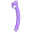
  • Chassis_Center.stl
  • Chassis_Left.stl
  • Chassis_Right.stl
  • Gear_Axle_Rear.stl
  • Gear_Idler_Large.stl
  • Gear_Idler_Small.stl
  • Gear_Spring.stl
  • Spacer_Axle_Gear_Idler_Large.stl
  • Spring.stl
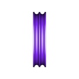
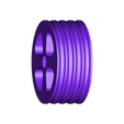
  • Wheel_Front.stl
  • Wheel_Rear.stl

Learn more about the formats

Publication date 2018-06-06 at 17:37
Design number 26425

3D printer file info

3D model description

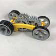
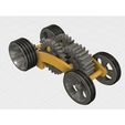
Tabletop Tri-Mode Spring Motor Rolling Chassis adds yet another mode to my previous spring motor designs, "pull back windup".

While this small vehicle will not outperform my previous designs for distance, it does add a third mode "pull back windup" to the power and true coast modes of my previous floating pinion designs (here: http://www.thingiverse.com/thing:2054125 and here: http://www.thingiverse.com/thing:2025760). The previous designs utilized a single floating pinion ("Drive Pinion") that allowed the vehicle to truly coast by disengaging the rear axle from the spring motor, but depended on a knob or key to wind the spring. This design adds a second floating pinion ("Wind Pinion") that provides the mechanism for winding the spring by rapidly rolling the vehicle in reverse, thus no knob or key are required.

Video of prototype is here: https://www.youtube.com/watch?v=nYvMv_0V4Kw.

You will need to purchase 12 "AS 568" size 221 (1 7/16 O.D., 1 11/16 I.D., 1/8" diameter) o-rings for the tires.

I probably forgot a file or two or something, so if you have any questions, please feel free to ask.

Designed using Fusion 360, sliced using Cura 2.3.1, and printed in PLA on an Ultimaker 3 Extended.

3D printing settings

Printer Brand:

Ultimaker

Printer:

Ultimaker 3 Extended

Rafts:

No

Supports:

No

Resolution:

.1mm

Infill:

100%, 20% (see Misc Notes)

Notes:
I printed "Spring.stl", "Gear Spring.stl" and all axles at 100%, the remaining components at 20%.

Post-Printing
Prior to assembly, test fit and trim, file, sand, etc. all parts as necessary for smooth movement of moving surfaces, and tight fit for non moving surfaces. Depending on the colors you chose and your printer settings, more or less trimming, filing and/or sanding may be required.

Study "Assembly.stl", carefully noting the locations and positions of the various components as assembly proceeds.

I assembled Table Top Tri-Mode Spring Motor Rolling Chassis as follows:

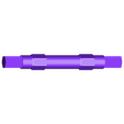
1) Press both "Gear Axle Rear.stl" onto "Axle Rear.stl".

2) Assemble "Spring.stl", "Gear Spring.stl" and "Cap Gear Spring.stl" onto "Axle Spring.stl".

3) Press "Axle Gear Idler Small.stl" into "Gear Idler Small.stl" for both gear idler small assemblies.

4) Press "Axle Gear Idler Large.stl" into "Chassis Right.stl".

5) Press the axle spring assembly into "Chassis Right.stl".

6) Position one of the gear idler small assemblies into "Chassis Right.stl", then press "Chassis Center.stl" into "Chassis Right.stl". Note the gear idler small assembly must freely spin and slide in the guide slot. This is the "Wind Pinion".

7) Position one "Gear Idler Large.stl" onto "Axle Gear Idler Large.stl".

8) Position "Spacer Axle Gear Idler Large.stl" onto "Axle Gear Idler Large.stl".

9) Position the remaining "Gear Idler Large.stl" onto "Axle Gear Idler Large.stl".

10) Position the remaining gear idler small assembly into "Chassis Center.stl". This is the "Drive Pinion".

11) Position the rear axle assembly into the chassis right assembly.

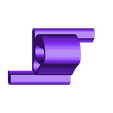
12) Press "Chassis Left.stl" onto "Chassis Right.stl". Note that all gears must move freely.

13) Press "Axle Front.stl" into one "Wheel Front.stl". Slide the assembly into the chassis assembly, then press the remaining "Wheel Front.stl" onto the remaining end of "Axle Front.stl".

14) Press both "Wheel Rear.stl" onto each end of the rear axle assembly.

15) At this point, the chassis should easily roll forward when pushed forward. When the chassis is rapidly moved in reverse, the winding floating pinion (the pinion adjacent to "Chassis Right.stl") should engage and cause a winding of the spring.

I do not recommend exceeding a 30" total rollback distance in order to avoid spring failure and/or separation from the spring gear.

Hope you like it!

Advertising


Issue with this design? Report a problem.

Would you like to support Cults?

You like Cults and you want to help us continue the adventure independently? Please note that we are a small team of 3 people, therefore it is very simple to support us to maintain the activity and create future developments. Here are 4 solutions accessible to all:

  • ADVERTISING: Disable your banner blocker (AdBlock, …) and click on our banner ads.

  • AFFILIATION: Make your purchases online by clicking on our affiliate links here Amazon.

  • DONATE: If you want, you can make a donation via Ko-Fi πŸ’œ.

  • WORD OF MOUTH: Invite your friends to come, discover the platform and the magnificent 3D files shared by the community!


Sharing and downloading on Cults3D guarantees that designs remain in makers community hands! And not in the hands of the 3D printing or software giants who own the competing platforms and exploit the designs for their own commercial interests.

Cults3D is an independent, self-financed site that is not accountable to any investor or brand. Almost all of the site's revenues are paid back to the platform's makers. The content published on the site serves only the interests of its authors and not those of 3D printer brands who also wish to control the 3D modeling market.

100% secure payment by credit card, PayPal, Apple Pay, Google Pay, etc.
View all payment options.