Purchase, Print and Prepare the Parts.
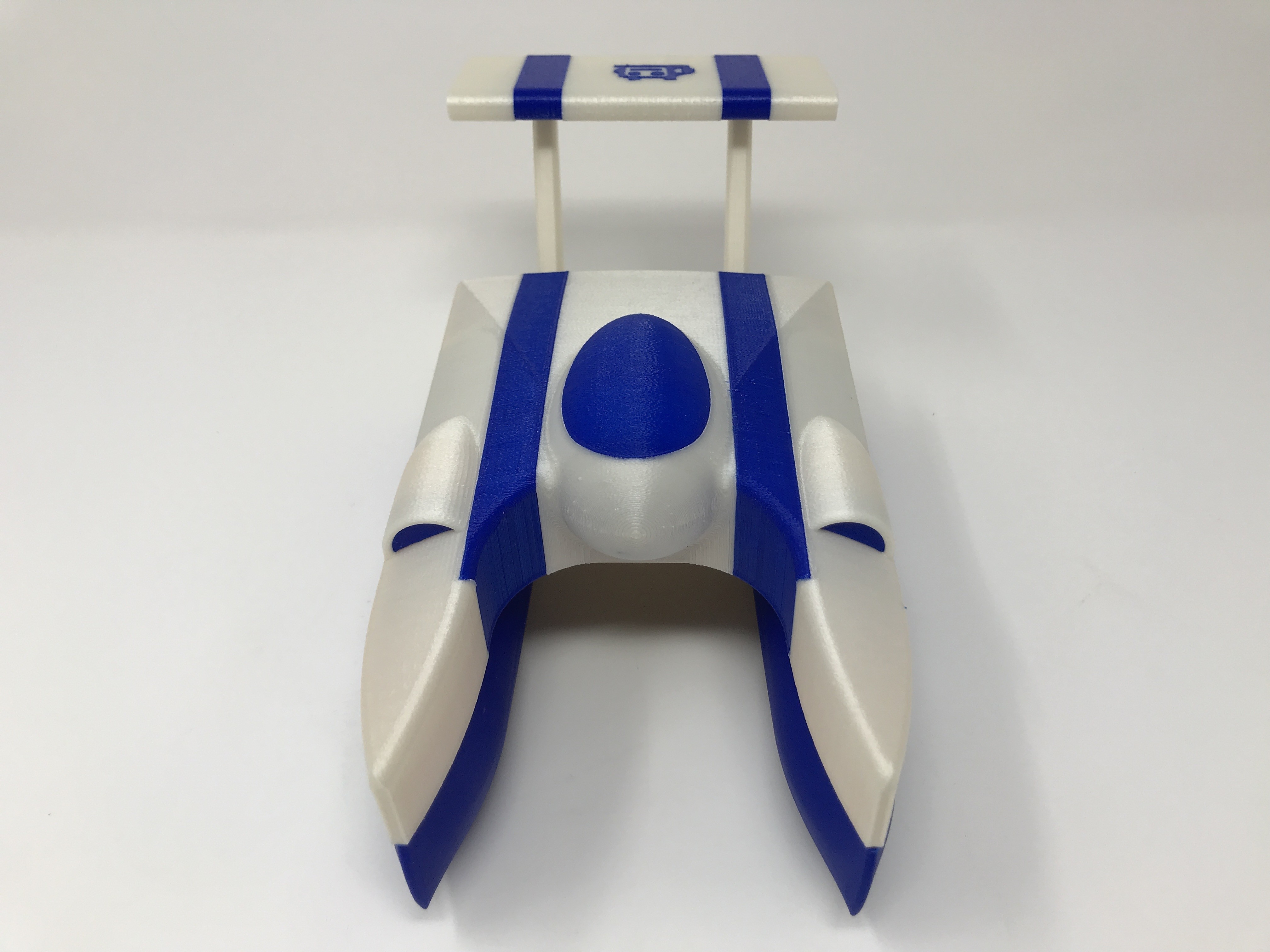
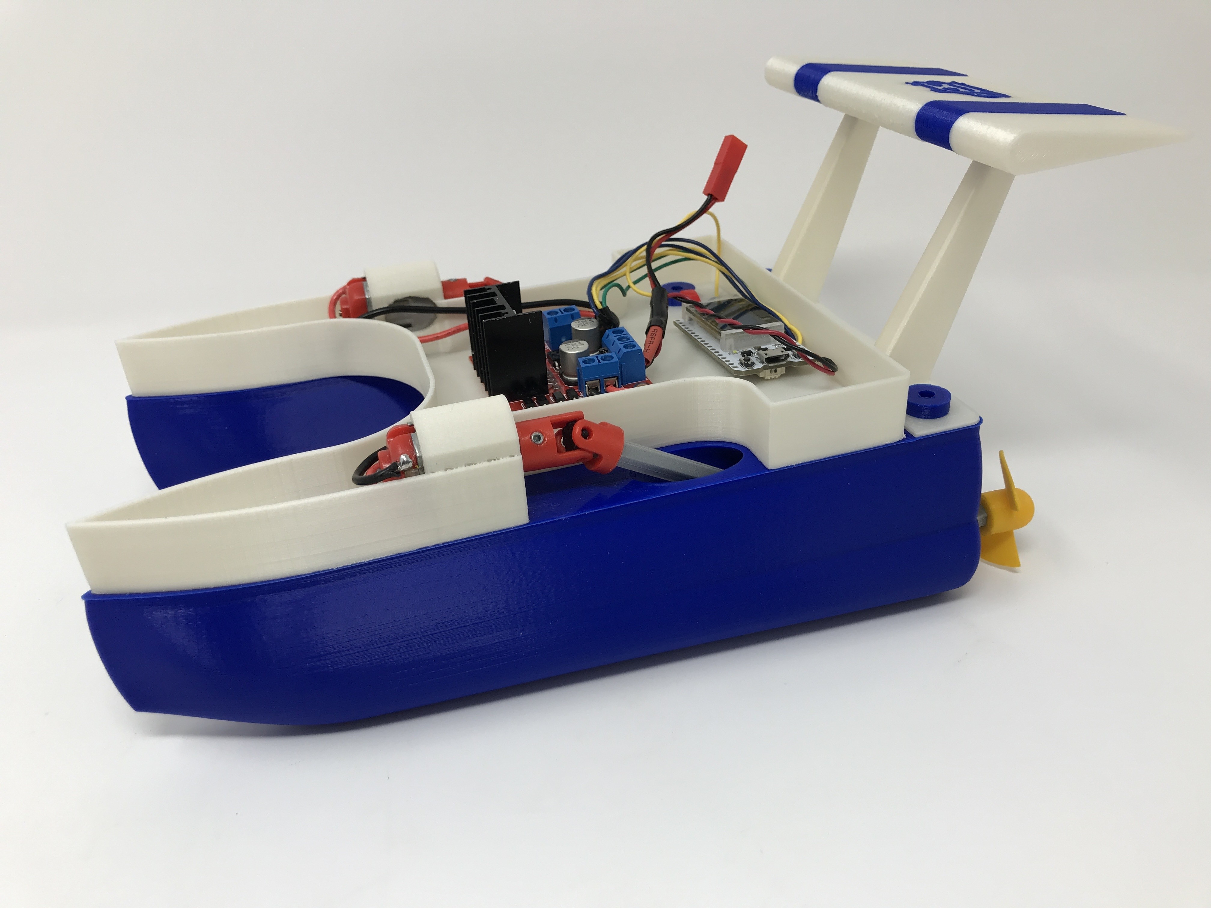
WiFi Propeller Boat II, like the original, is a challenge to print, assemble and wire and requires plenty of patience to complete.
Before you begin, note that WiFi Propeller Boat II contains large, flat components that may not fit your build area and if they do, warping can become a significant issue so use a brim and your best techniques for build plate adhesion. There are also some very small parts (so small I've lost a few dropping them on my shop floor) and thin walled parts (as thin as 1.2mm), so before printing, test each part using your slicer in layer mode to confirm your printers ability to print the parts.
I purchased the following parts for WiFi Propeller Boat:
1 Heltec WiFi Kit 32 with Oled display (on line).
1 Timesetl L298N Motor Drive Controller (on line).
2 Micro 130 DC Motors (on line).
2 10 by 15 by 4mm sealed ball bearings (I used a ProtekRC PTK-10046, local hobby shop).
1 Ares AZSZ2503 1200 mAh 2-Cell/2S 7.4V 25C Lipo Battery (local hobby shop).
1 JST Female Connector (sized for battery, local hobby shop).
4 3 by 5mm set screws (local hobby shop).
1 2k ohm resistor (local hobby shop).
1 1k ohm resistor (local hobby shop).
You will also need cyanoacrylate glue, servo tape, acrylic caulk, needle nose pliers and assorted precision hand tools, jewelers files, wire cutters, wire strippers, solder and soldering iron, and maybe clear PLA safe spray paint.
I printed "Axle, Propeller.stl", "Axle.stl", "Bolt, 8 by 1.25mm.stl", "Bushing.stl", "Cross Journal.stl", "Propeller Port.stl", "Propeller Starboard.stl", "Yoke Motor.stl" and "Yoke.stl" at .1mm layer height with 100% infill. I printed the remaining components at .15mm layer height with 20% infill. I printed "Cover.3mf' and "Deck.stl" with PLA support, "Propeller Port.stl" and "Propeller Starboard.stl" with Ultimaker Breakaway support, and the remaining parts with no support.
I printed the following quantities of each part:
2 Axle, Propeller.stl
2 Axle.stl
6 Bolt, 8 by 1.25mm.stl 2 Bushing.stl
1 Cover.3mf (I've included Cover.stl for single extrusion)
4 Cross Journal.stl
1 Deck.stl
2 Hull.stl
1 Mount, Wing.stl
1 Propeller Port.stl
1 Propeller Starboard.stl
1 Wing.3mf (I've included Wing.stl for single extrusion)
2 Yoke Motor.stl
6 Yoke.stl
Prior to assembly, test fit and trim, file, sand, etc. all parts as necessary for smooth movement of moving surfaces, and tight fit for non-moving surfaces. Depending on the colors you chose and your printer settings, more or less trimming, filing and/or sanding may be required. Carefully file all edges that contacted the build plate to make absolutely sure that all build plate "ooze" is removed and that all edges are smooth. I used small jewelers files and plenty of patience to perform this step. The model uses threaded assembly (8 by 1.25mm) thus an 8 by 1.25mm tap and die may be needed to clean the threaded components.
Regarding the hulls, after printing, completely insert the 6 bolts into the threaded holes on the top of the hulls, submerse each hull under water for about a minute, remove, dry off and shake to see if any water has leaked into the hull. If so, spray a few lite coats of clear PLA safe spray paint onto the hull, allow to dry, and test again.
Program the WiFi Kit 32
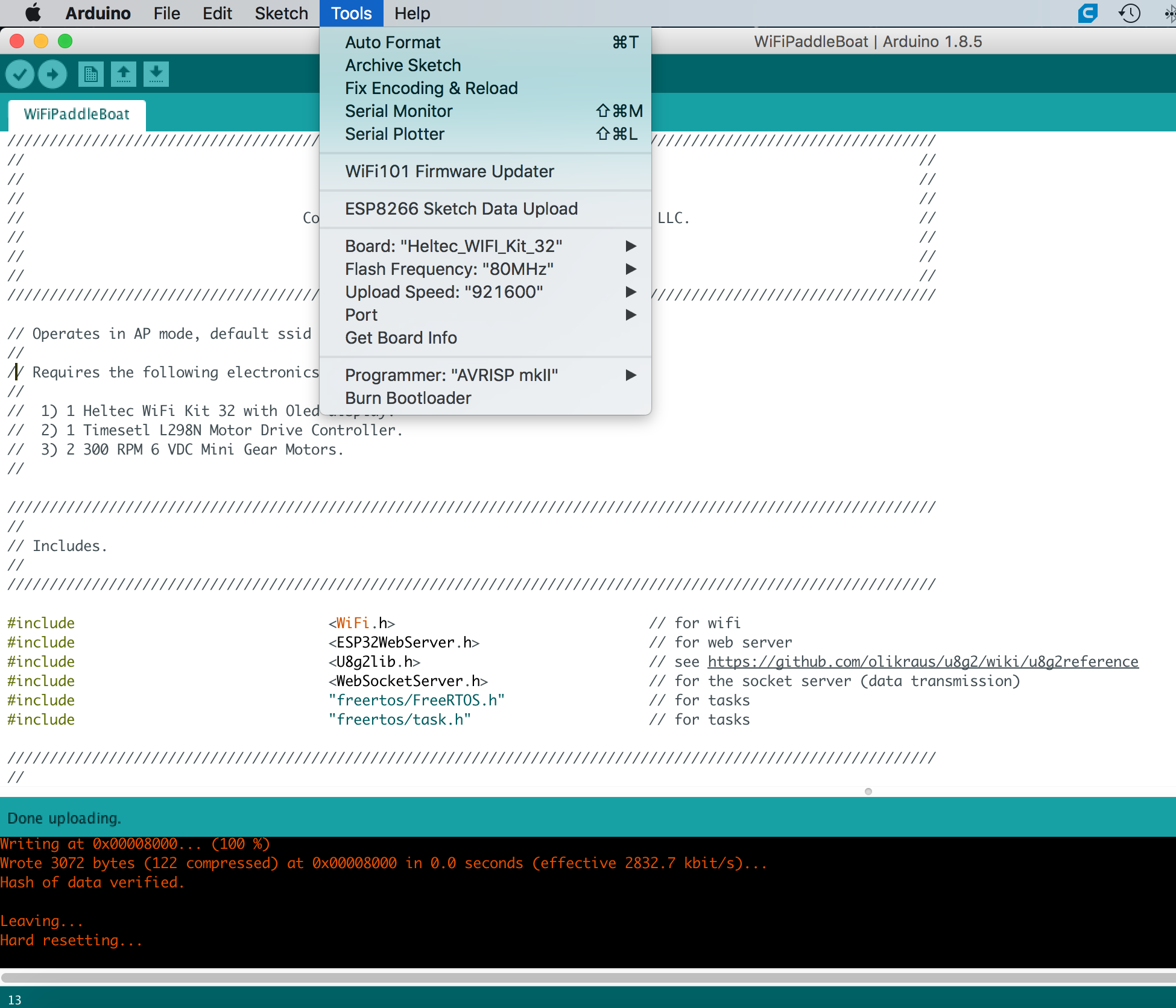
WiFi Propeller Boat was written in the Arduino environment for the ESP32 chip. There are numerous excellent tutorials around the web detailing the use of the Arduino environment, therefore I won't duplicate them here.
Regarding the WiFi Propeller Boat web page, I used an html "canvas" element for the graphics, and the canvas events "touchstart", "touchmove" and "touchend" for control. I'm of the belief the software should work on touch enabled devices other than iOS, but have not been able to confirm that it will.
With the Heltec Wifi Kit 32 connected to your computer via a USB cable, open the Arduino environment and load the file "WiFiPropellerBoat.ino". At the top of the file there are a series of include files (files ending in ".h"). Make sure you have the library associated with each of these include files installed in your Arduino environment.
WiFi Propeller Boat operates in access point mode (this mode is similar to the various small sport cameras) in that you connect your smart phone wifi directly to WiFi Propeller Boat wifi. I programmed "WiFiPropellerBoat" with the ssid "WiFiPropellerBoat", password of "WiFiPropellerBoat", and IP address of "192.168.20.20". Before compiling and downloading the software to the WiFi Kit 32, you may wish to change these parameters to suit your needs.
After all libraries are installed and the ssid, password and ip address are set, compile and download the software to the WiFiKit 32. Once downloaded, the WiFi Kit 32 OLED should display the title, copyright, and finally the AP name and IP address. Go to the wifi settings on your smart phone and log onto the WiFi Kit 32 access point ssid using the password.
When the wifi connection is complete, open a web browser on your smart phone and navigate to the ip address. If successful, a flashing "stop sign" styled image should appear on the middle of the WiFi Kit 32 OLED, and a blue dot should appear on your smart phone display. If you drag the blue dot to the top of the display, an up arrow should appear along with two power level indicators on the WiFi Kit 32 OLED. Drag the blue dot around the smart phone display and examine the OLED response.
Wiring.
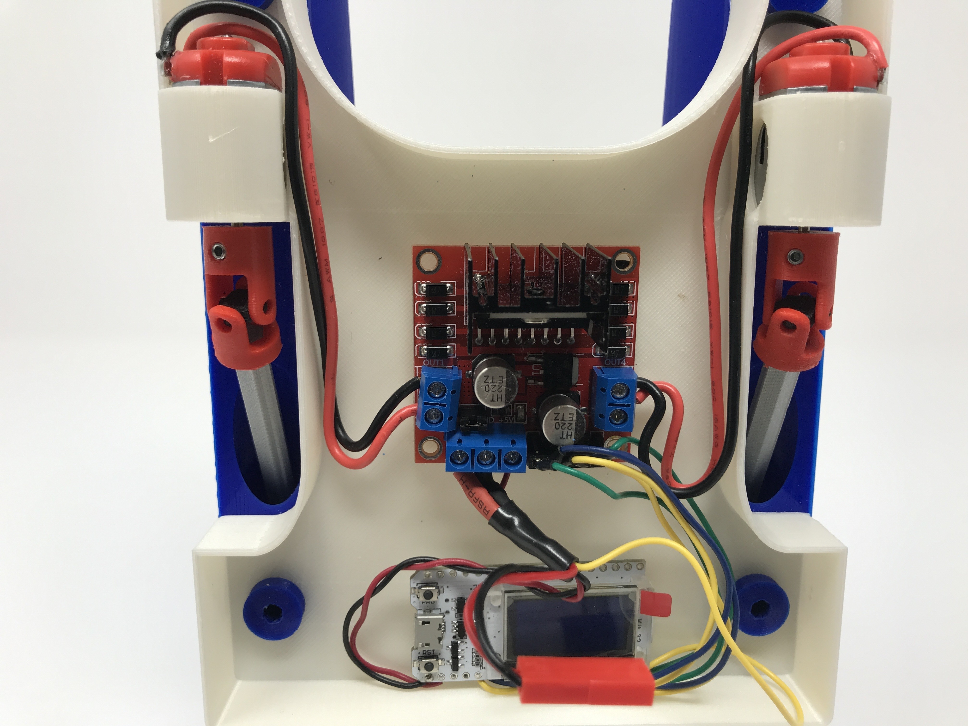
To connect the motor speed controller to the motors and WiFi Kit 32, I performed the following steps.
The port (left) motor is connected to the motor speed controller OUT4 ("-") and OUT3 ("+") screw terminals. Solder a 100mm length of AWG 16 red wire to the port motor "+" terminal, and a 100mm length of AWG 16 black wire to the port motor "-" terminal. Noting the solder tabs on the motor are quite flimsy, a used small dots of cyanoacrylate to glue between the wires and motor end cap. Tin the free ends of these wires, then connect the tinned free end of the red wire to motor speed controller OUT3 terminal, and the tinned free end of the black wire to the OUT4 terminal.
The starboard (right) motor is connected to the motor speed controller OUT1 ("-") and OUT2 ("+") screw terminals. Solder a 100mm length of AWG 16 red wire to the starboard motor "+" terminal, and a 100mm length of AWG 16 black wire to the starboard motor "-" terminal. Tin the free ends of these wires, then connect the tinned free end of the red wire to motor speed controller OUT2 terminal, and the tinned free end of the black wire to the OUT1 terminal.
On the motor speed controller board, the 6 pin header styled connector provides the motor control interface. I used a 6 pin Arduino styled female header connector and soldered the control wires between this header connector and the Heltec WiFi Kit 32 as follows:
Solder a 100mm length of AWG 26 green wire between pin 26 on the WiFi Kit 32 and the ENA header pin on the motor speed controller header.
Solder a 100mm length of AWG 26 blue wire between pin 12 on the WiFi Kit 32 and the IN1 header pin on the motor speed controller header.
Solder a 100mm length of AWG 26 yellow wire between pin 13 on the WiFi Kit 32 and the IN2 header pin on the motor speed controller header.
Solder a 100mm length of AWG 26 blue wire between pin 27 on the WiFi Kit 32 and the IN3 header pin on the motor speed controller header.
Solder a 100mm length of AWG 26 yellow wire between pin 14 on the WiFi Kit 32 and the IN4 header pin on the motor speed controller header.
Solder a 100mm length of AWG 26 green wire between pin 25 on the WiFi Kit 32 and the ENB header pin on the motor speed controller header.
The motor speed controller also provides regulated 5vdc on the 3 pin screw terminal which I used to power the WiFi Kit 32. To connect power from the motor speed controller to the WiFi Kit 32, solder a 100mm length of AWG 26 red wire to the WiFi Kit 32 5V pin. Next, solder a 100mm length of AWG 26 black wire to the WiFi Kit 32 GND pin. Tin the free ends of both wires, then connect the tinned free end of the red wire to the motor speed controller +5V pin on the 3 pin screw connector, and connect the tinned free end of the black wire to the motor speed controller GND pin on the 3 pin screw connector.
The entire circuit is powered by the 7.4vdc 1200ma LiPo battery. To connect the battery to the motor speed controller, attach the JST female connector red wire to the motor speed controller +12V pin on the 3 pin screw terminal, and the JST female connector black wire to the GND pin on the 3 pin screw terminal (this terminal shares grounds with the WiFi Kit 32 ground).
And finally, to monitor battery voltage, attach one end of the 2k ohm resistor to the motor speed controller +12 pin on the 3 pin screw terminal. Next attach one end of the 1k ohm resistor to the motor speed controller GND pin on the 3 pin screw terminal. Next, solder the two free ends of the resistors together, then solder a 100mm length of AWG 26 yellow wire between the resistor solder joint and pin 36 the WiFi Kit 32. Double check all wiring.
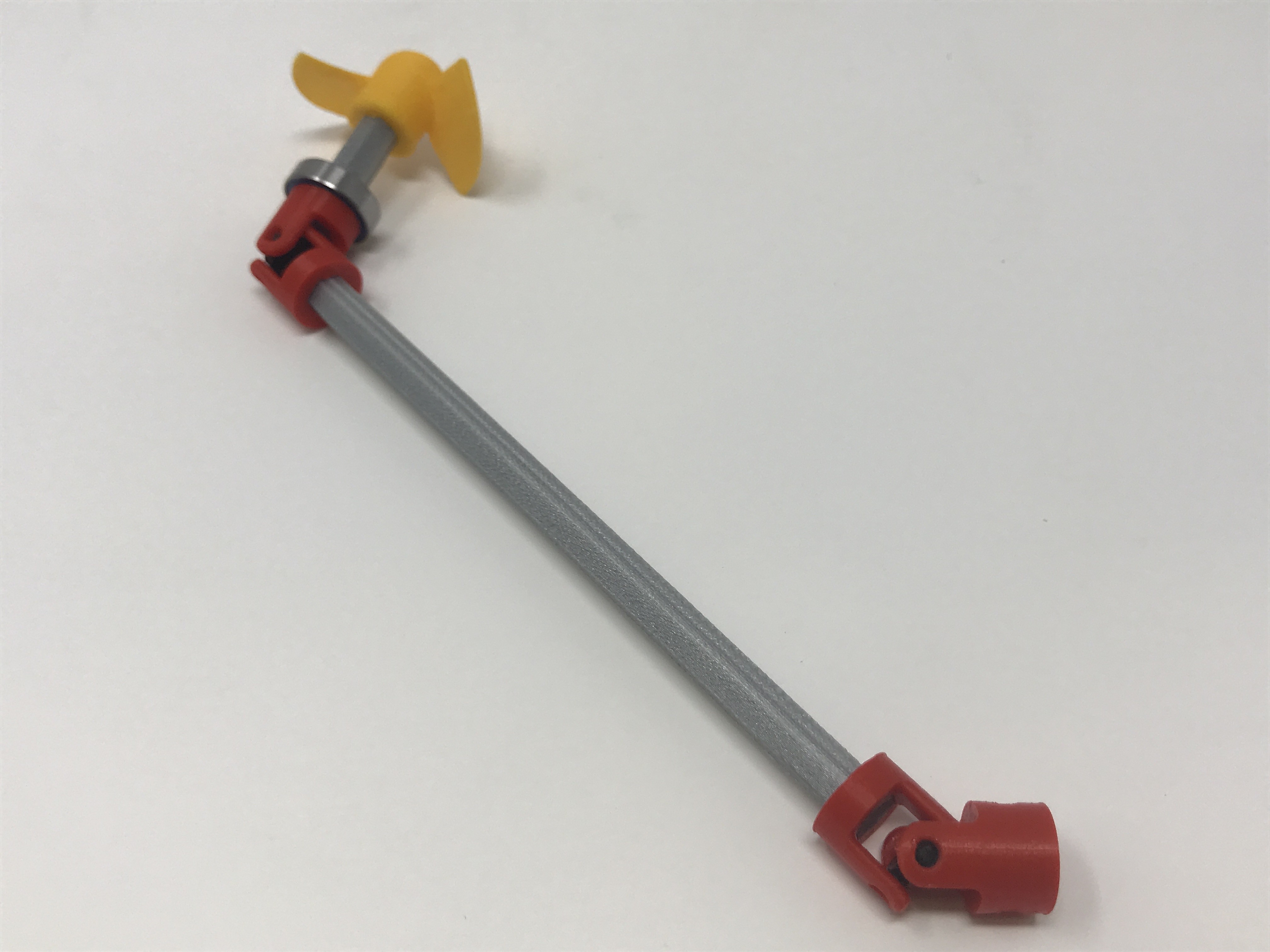
Assemble the Drive Shafts.
Two lower yoke assemblies and two upper yoke assemblies are required to assemble the drive shafts.
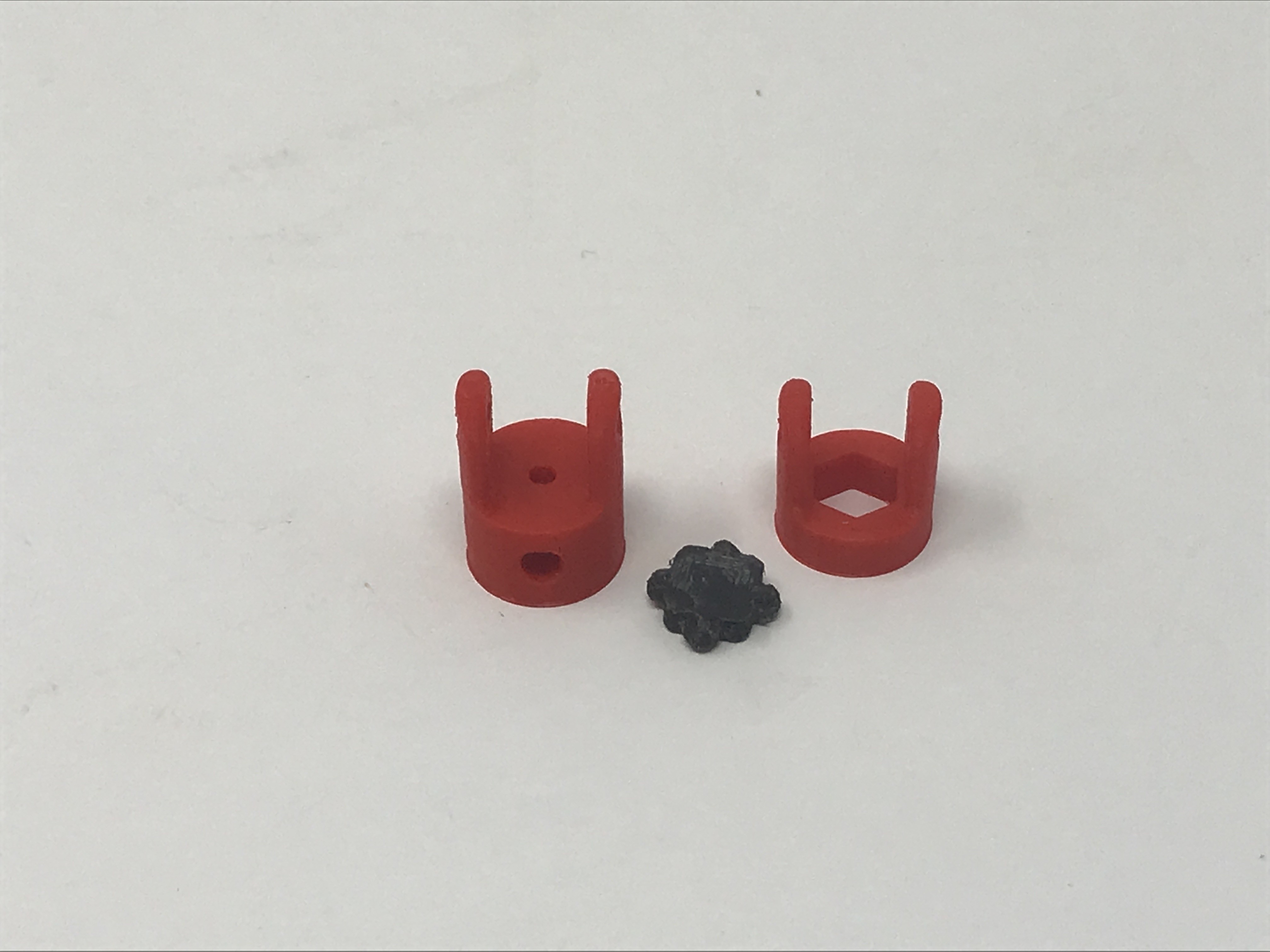
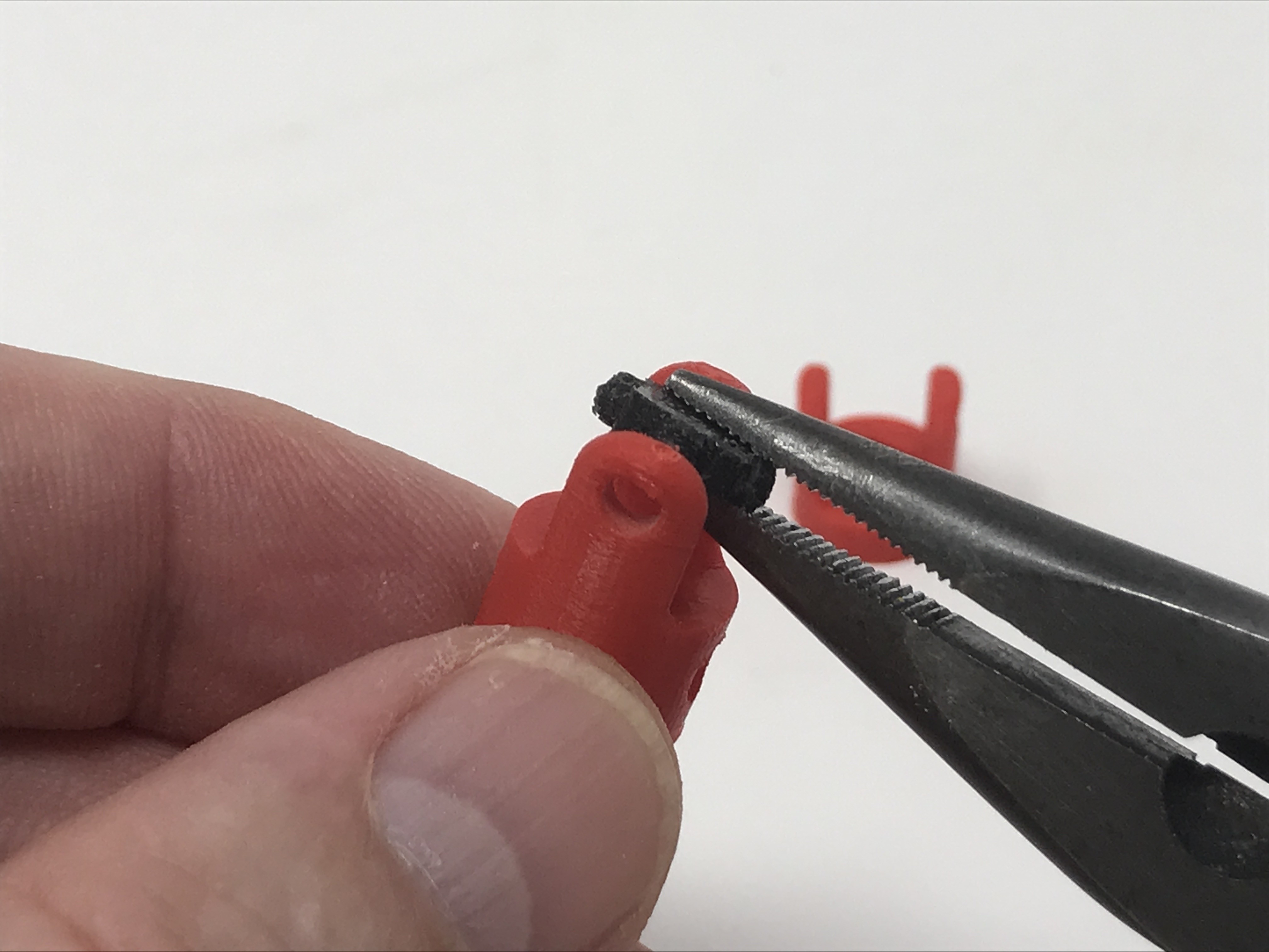
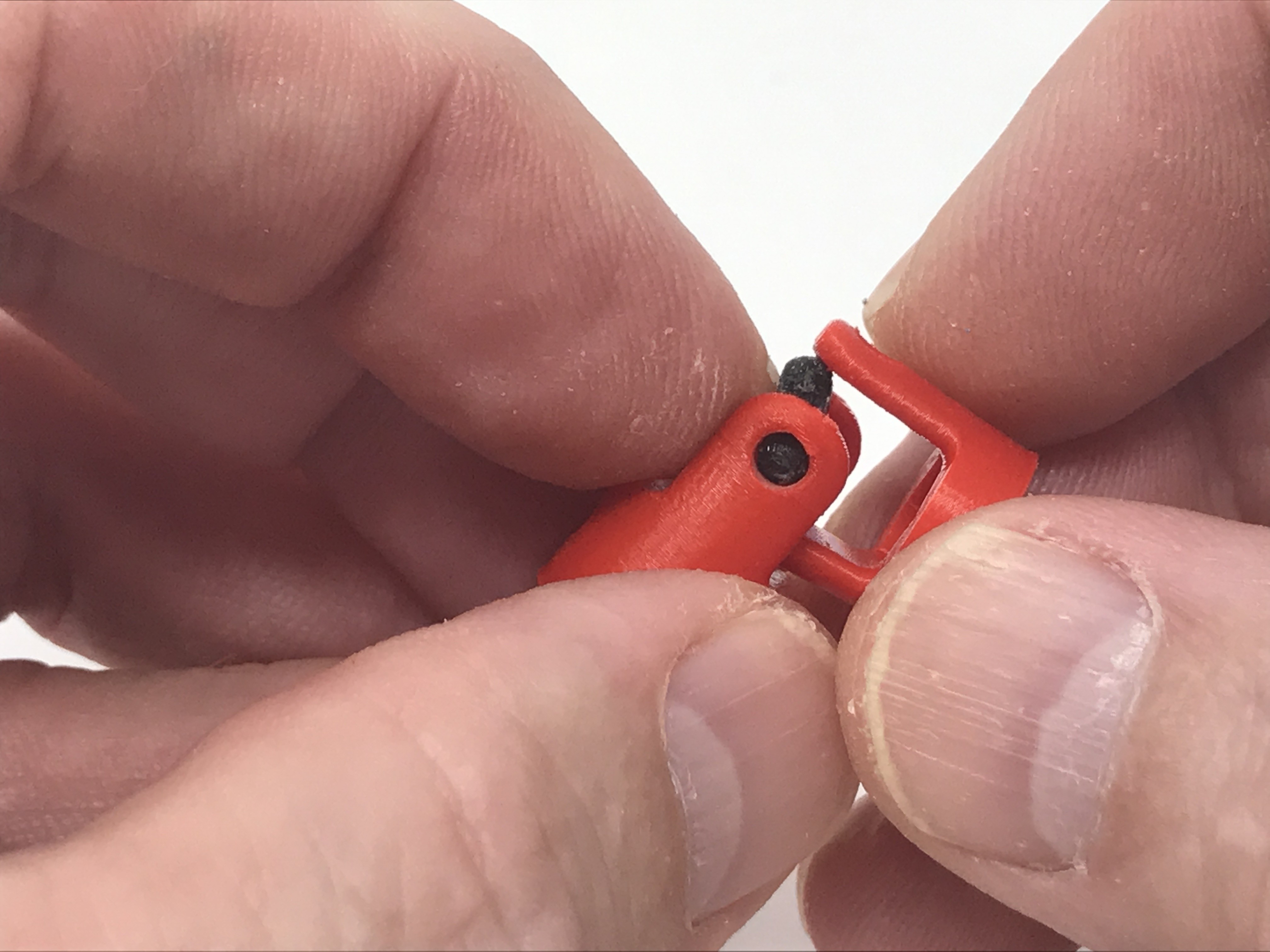
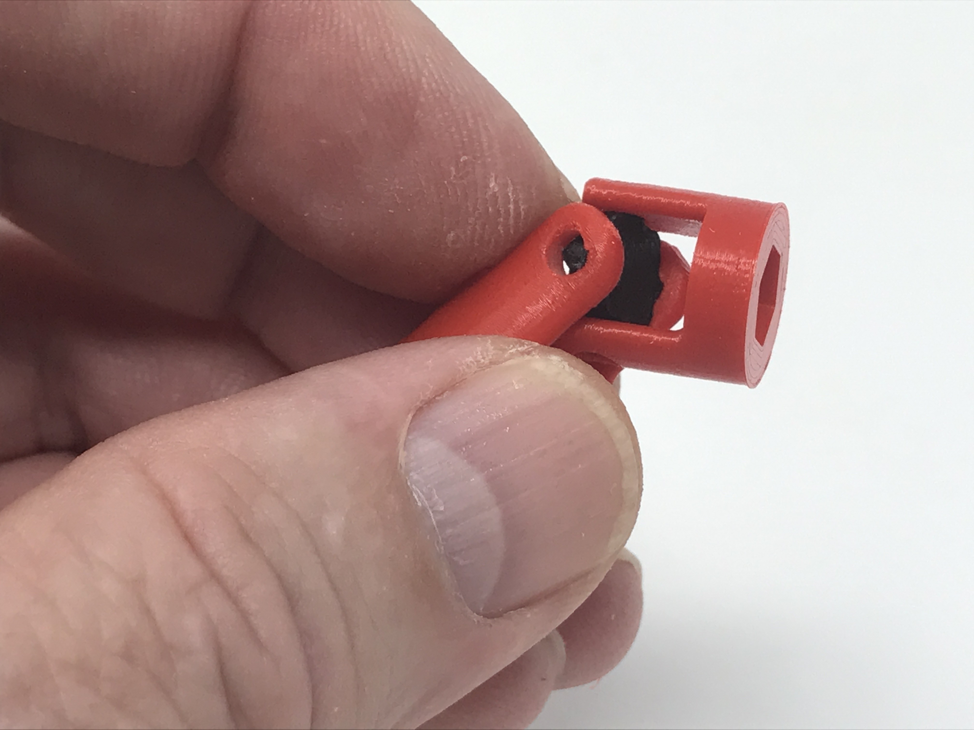
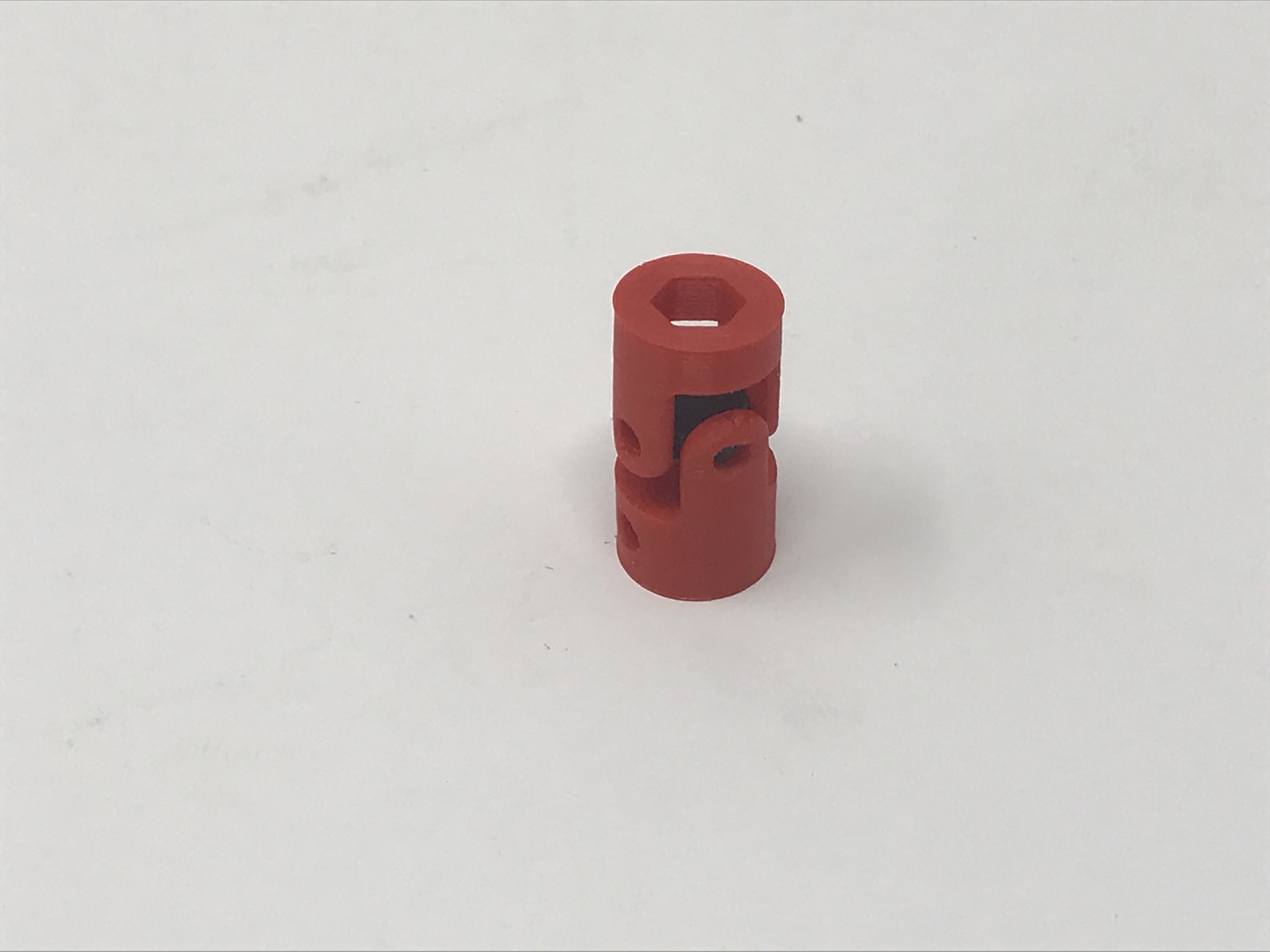
The parts required for a lower yoke assembly are 2 "Yoke.stl" and 1 "Cross Journal.stl". Begin by snapping a cross journal into one of the yokes as shown. I used a needle nose plier to assist in this step. Next, carefully snap the remaining yoke onto the cross journal. When completed, the assembly should easily and smoothly rotate on both axis. Repeat this process for the second lower yoke assembly.
The parts required to assemble an upper yoke are 1 "Yoke.stl", 1 "Yoke Motor.stl" and 1 "Cross Journal.stl", and they assemble the same as the lower yoke assembly. Repeat the process for the second upper yoke assembly.
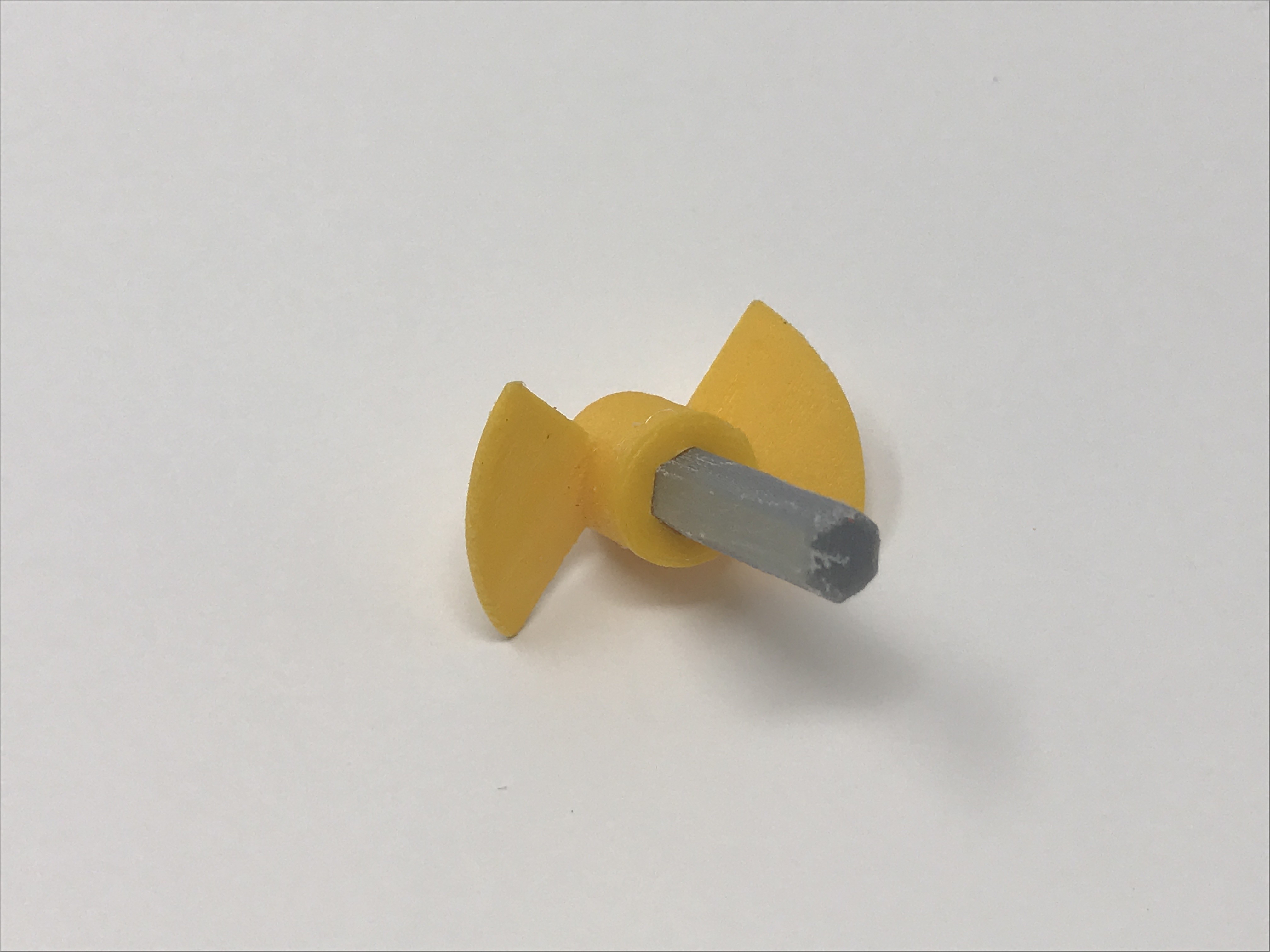
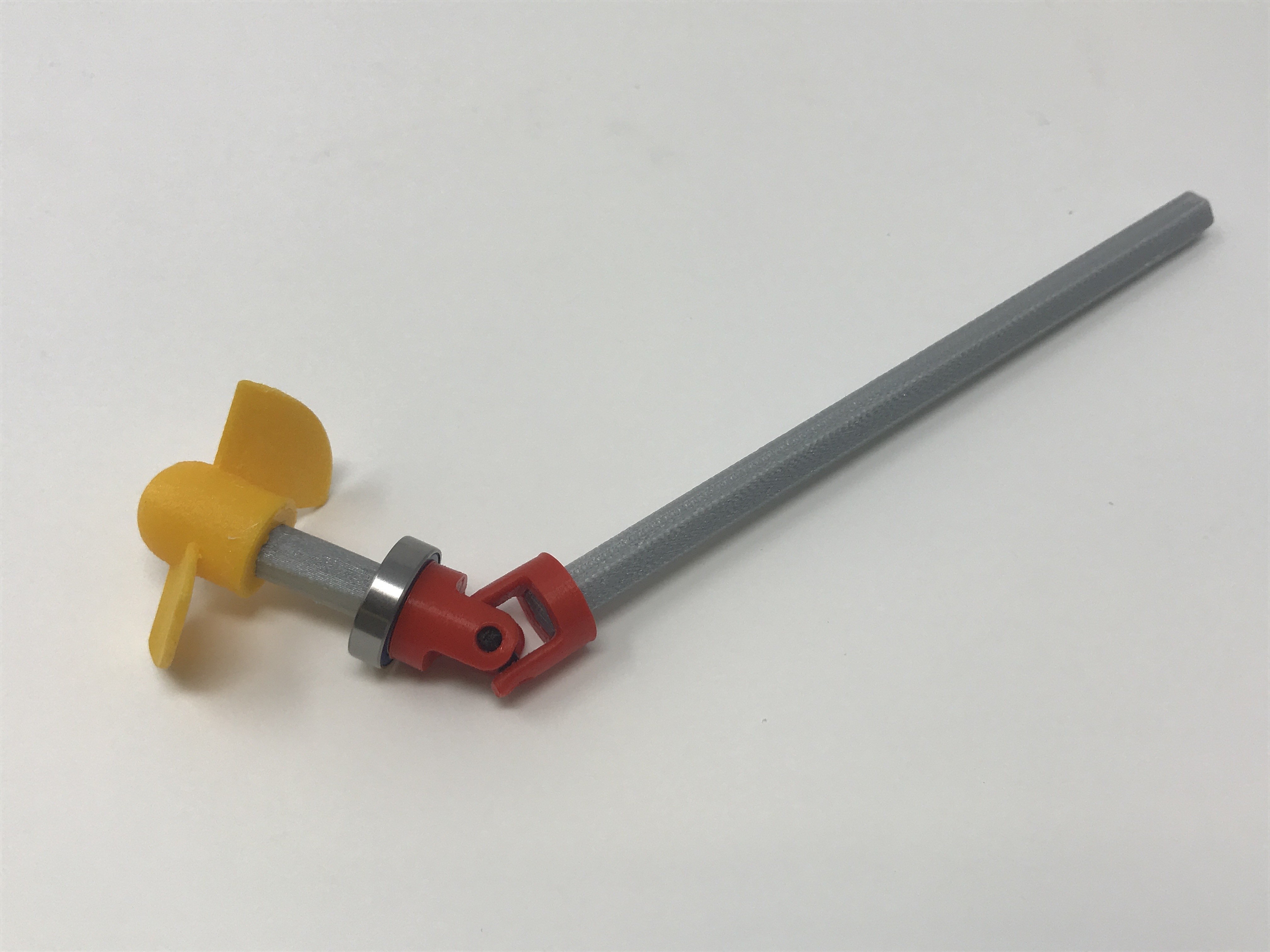
With the upper and lower yoke assemblies complete, next press "Propeller Port.stl" onto on of the "Axle, Propeller.stl". This should be a very tight fit. Repeat this process with "Propeller Starboard.stl" and the remaining propeller axle.
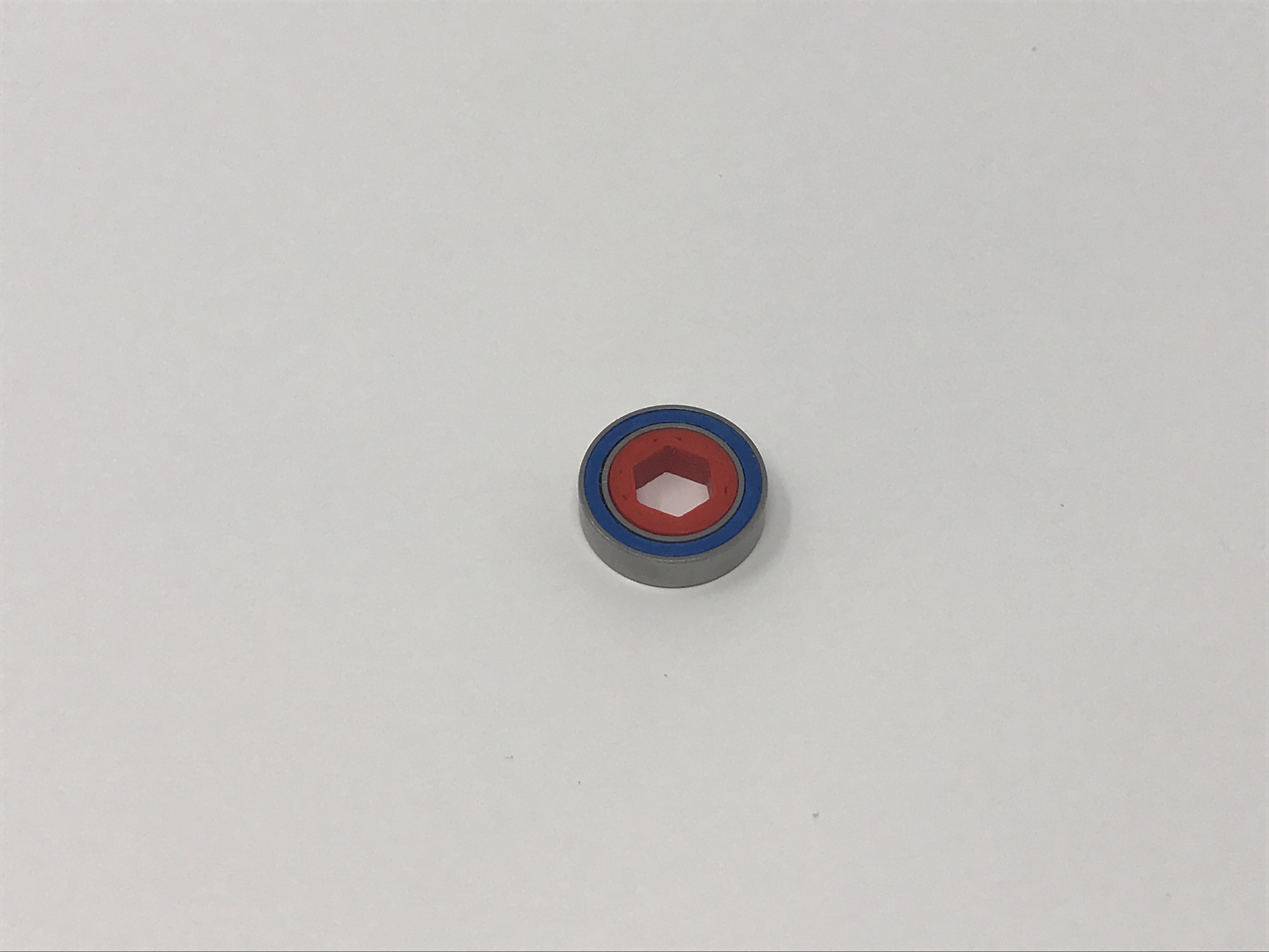
Next press one "Bushing.stl" into one of the 10 by 15 by 4mm sealed bearings. This should be a tight fit. Repeat this process with the remaining bushing and bearing.
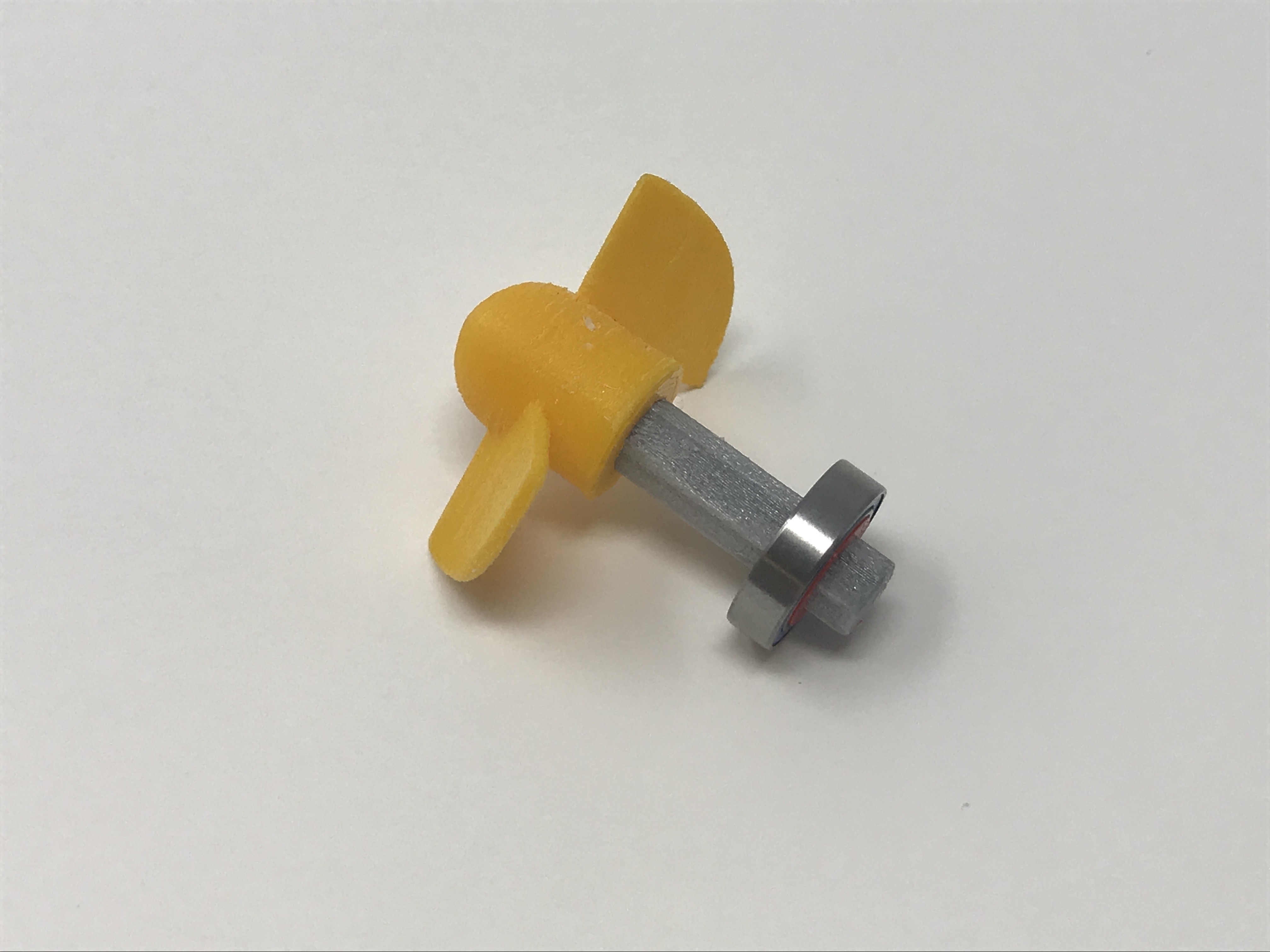
Press one of the bushing / bearing assemblies onto one of the propeller axles as shown, 4mm from the end of the axle. This should be a tight fit. Repeat this process with the remaining assembly.
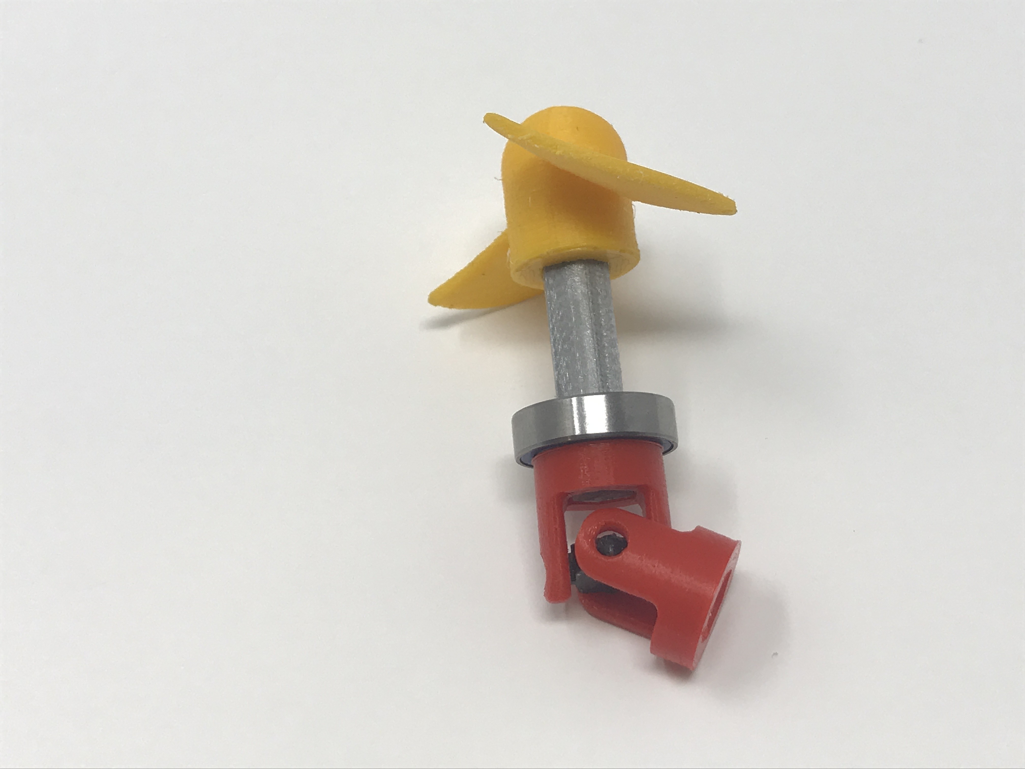
Press one of the lower yoke assemblies onto one of the propeller axles as shown, making sure the end of the axle is flush with inner surface of the yoke as shown. This should be a tight fit. Repeat this process with the remaining assembly.
Press one "Axle.stl" into one of the free yoke on the lower yoke assembly as shown, making sure the end of the axle is flush with the inner surface of the yoke as shown. This should be a tight fit. Repeat this process with the remaining assembly.
Press one upper yoke assembly onto the free end of "Axle.stl" as shown, making sure the end of the axle is flush with the inner surface of the yoke as shown. This should be a tight fit. Repeat this process with the remaining assembly.
Using a 1.5mm hex wrench, thread the 3 by 5mm set screws into the motor yokes.
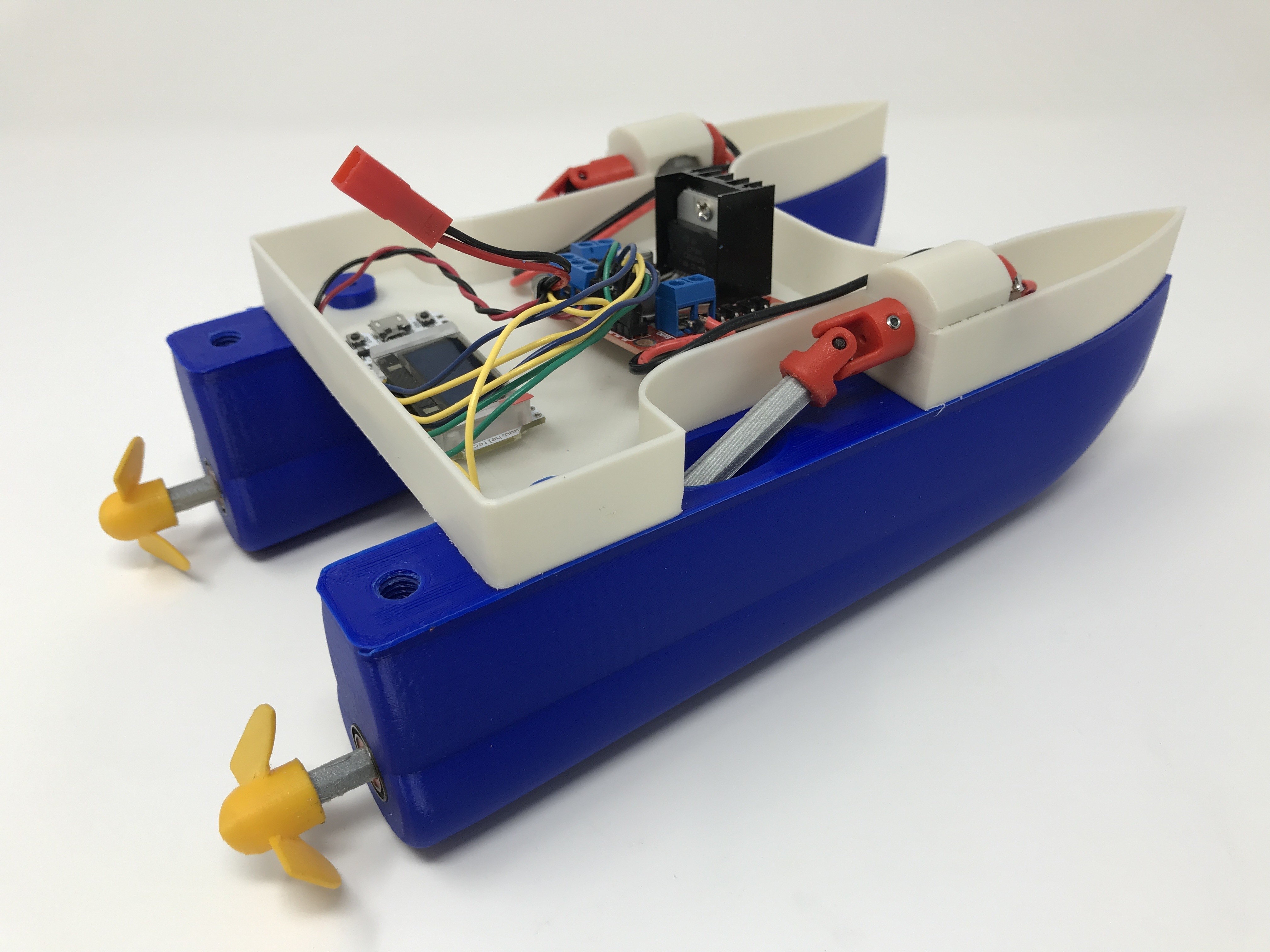
Final Assembly.
Apply a bead of silicon caulk around the underside of the 4 holes in "Deck.stl", then secure one "Hull.stl" under the deck using two "Bolt, 8 by 1.25mm.stl" as shown. Repeat this process with the remaining hull.
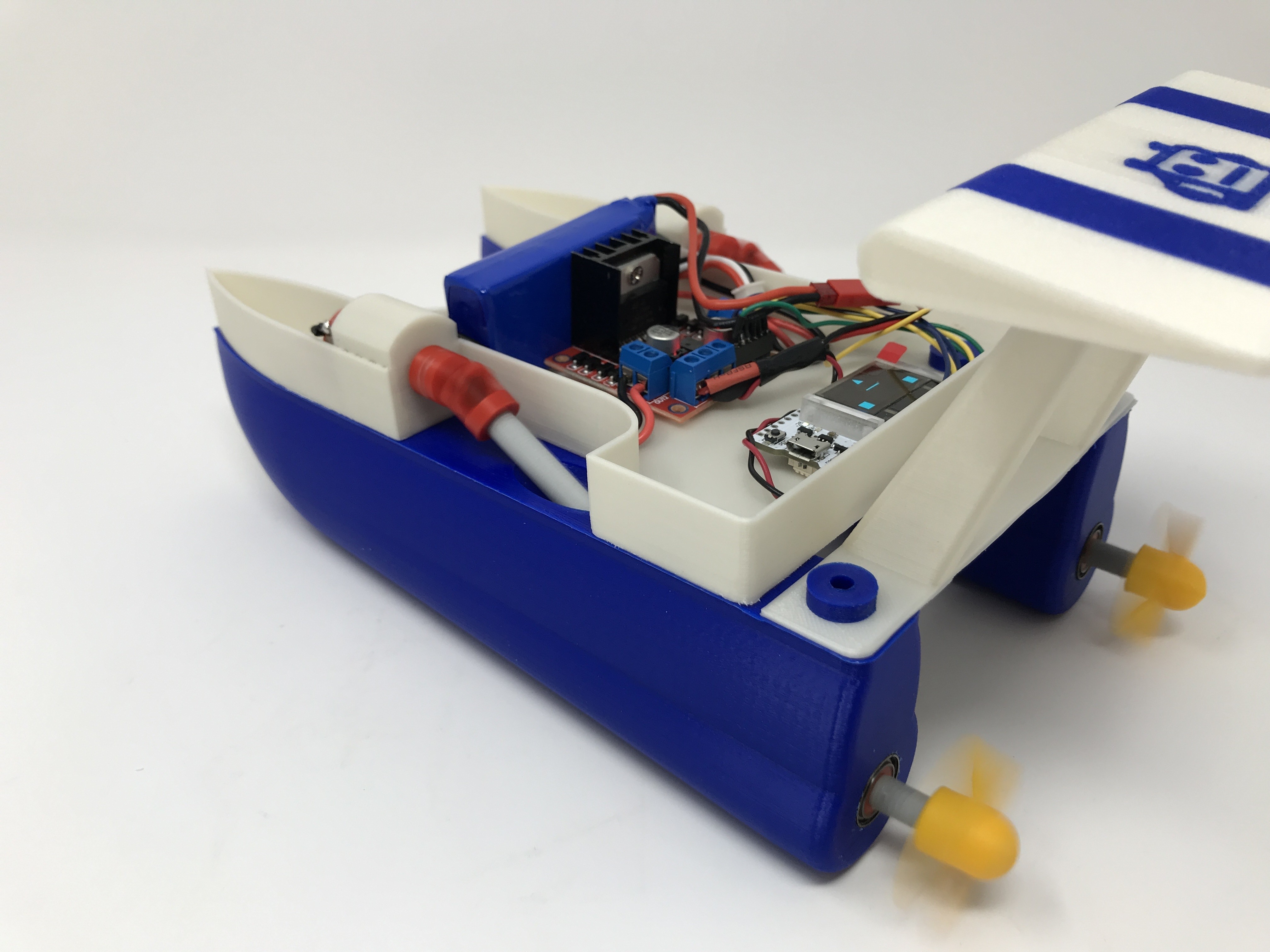
Press the motors into their positions in the deck as shown. The motor wires will be close to the outside of the hull, and the motor vents will be toward the elliptical hole in the deck motor mounts.
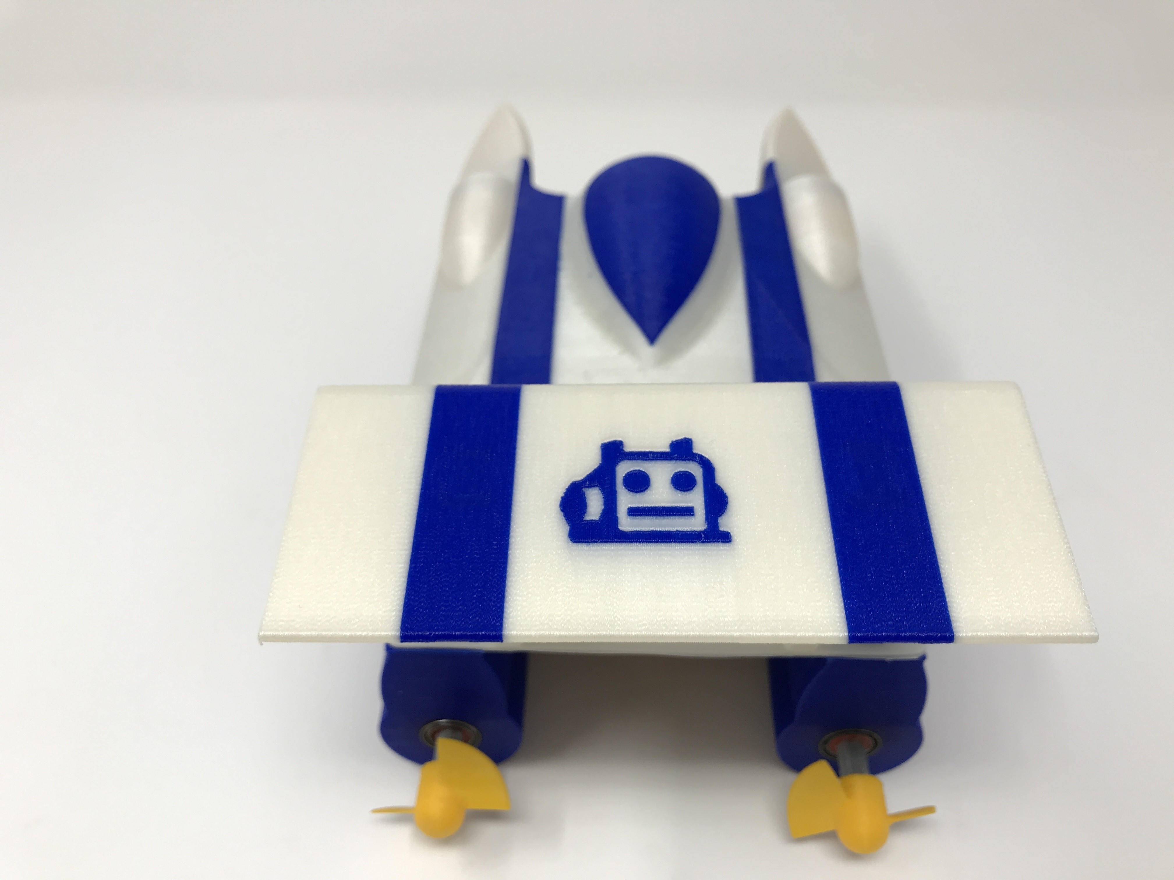
Carefully insert the propeller port axle assembly, motor yoke end first, into the rear hole of the port hull, sliding it fully into place until the motor yoke is fully engaged on the port motor shaft and the bearing is flush with the outside hull surface (this will be a tight fit). Carefully tighten the two set screws in the motor yoke until the yoke is securely fastened to the motor. Make certain the screws are firmly in contact with the motor shaft, as if the motor shaft slips inside of the motor yoke, friction and thus heat will be generated which will distort the motor yoke. Repeat this process with the propeller starboard axle assembly on the starboard hull.
Place the motor speed controller and WiFi Kit 32 into position as shown and secure in place with servo tape.
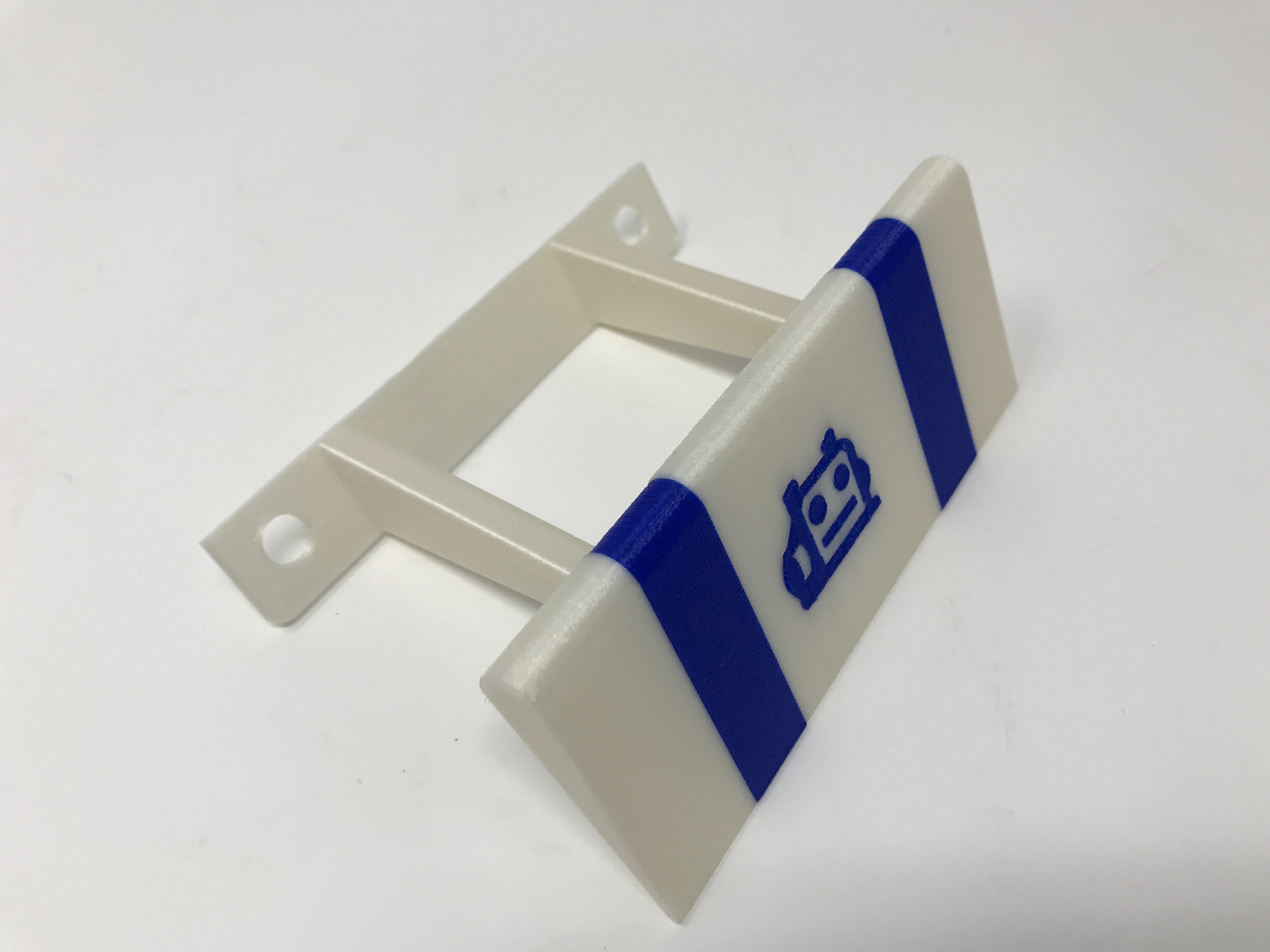
Press the wing onto the wing mount (this should be a very tight fit, if not, use cyanocacrylate to secure it in place) Using the remaining two "Bolt, 8 by 1.25mm.stl" , attach the wing assembly to the rear of the hulls as shown.
Position the battery as shown.
Plug the battery into the motor speed controller and check for proper display operation.
Test.
With assembly complete and before the first water test, I perform the following tasks:
Place WiFi Propeller Boat II on a flat surface with the propellers hanging free (over the edge).
Plug in the battery.
Connect a wifi enabled device to the WiFi Propeller Boat wifi (my WiFi Propeller Boat ssid is "WiFiPropellerBoat").
Open a web browser on a wifi enabled device.
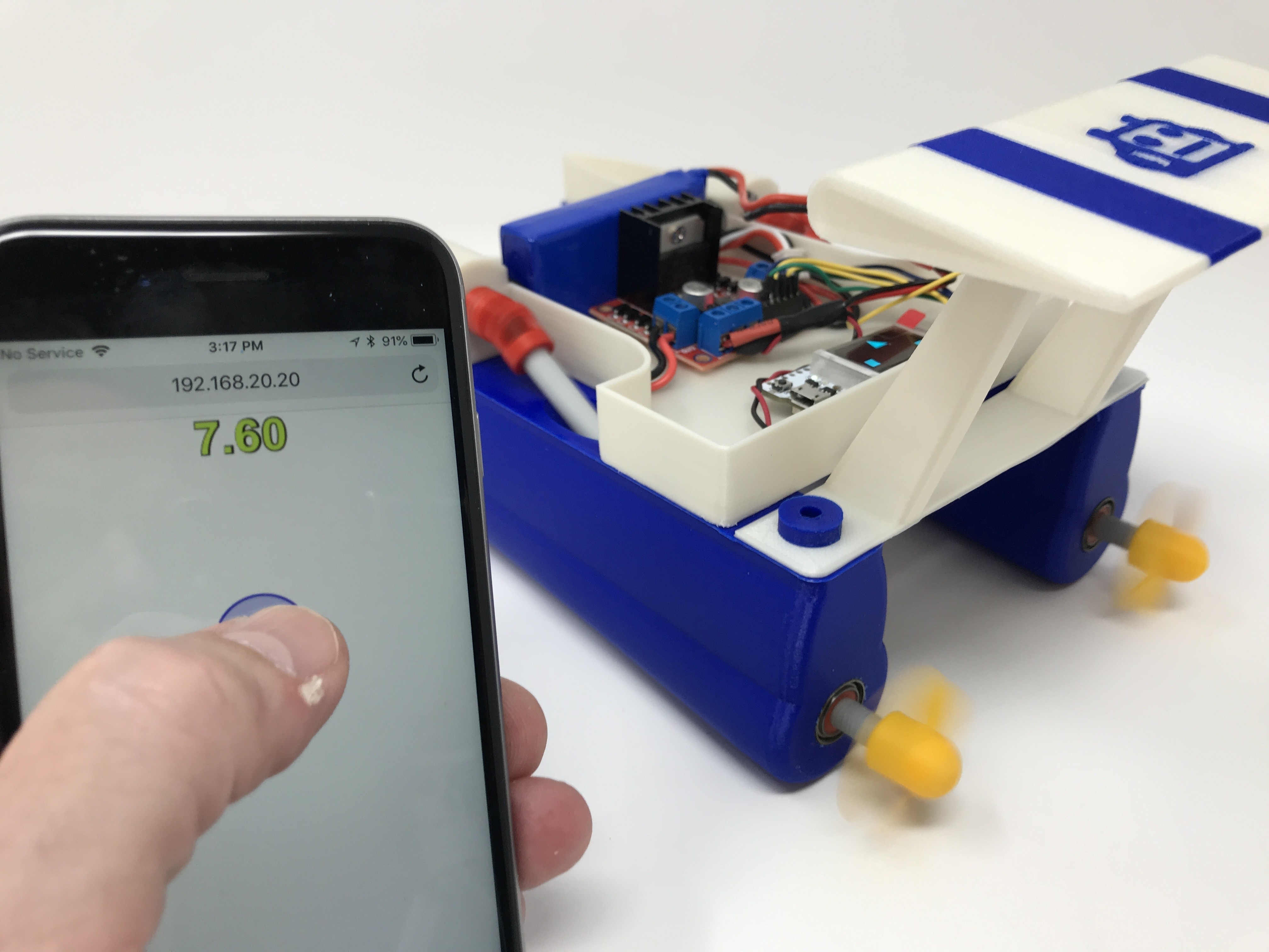
Navigate to the WiFi Propeller Boat ip address (my WiFi Propeller Boat ip address is 192.168.20.20).
When the blue dot appears on the web browser, a "stop sign" style image appears flashing on the WiFi Kit 32 OLED. Drag the dot to the top center of the display and the OLED display shows an up arrow and 2 power level indicators (one for the port motor, and a second for the starboard motor). Make sure the propellers are turning in the correct direction. Move the dot to the bottom center of the display and watch for proper OLED indications and propeller movement.
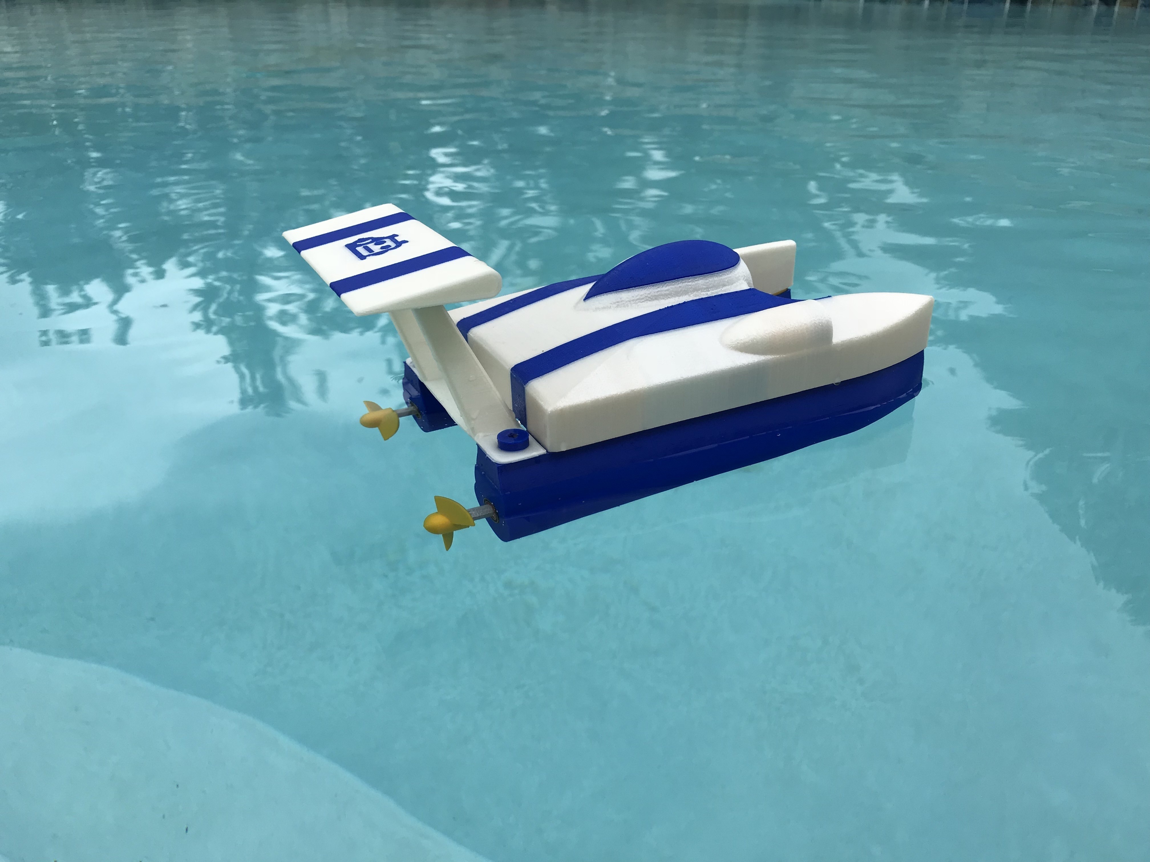
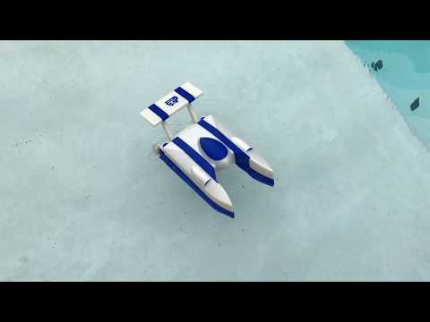
With that complete, place the cover over the electronics bay in the deck, place WiFi Propeller Boat II in the water, and off you go!
That's how I printed, programmed, wired and assembled WiFi Propeller Boat II.
Hope you enjoy it!
:format(webp)/https://fbi.cults3d.com/uploaders/13550170/illustration-file/d8e575c5-c012-4e9c-83d5-4215a3d9e735/IMG_1337_COVER.jpg)