Introduction
This astrophotography tracker was designed for use with a lightweight camera & lens combination to allow long-duration photographs to be taken of the night sky. It was created to meet my specific needs but, as it's designed using OpenSCAD, it should be readily adapted if any changes need to be made.
So far this has only been tested by tracking the sun as the night skies where I live are heavily polluted by light from neighbouring towns and industrial areas. I haven't had a chance to photograph any stars at the time of publishing this design - I'm waiting for an opportunity to get to a truly dark location.
I should add that I am a novice in the world of astrophotography, so I might have made some inaccurate assumptions - if you spot any, please let me know in the comments.
Acknowledgements
I will say up-front that significant parts of this tracker were put together after studying other people's designs. I haven't copied any part directly, but their ideas kicked off my own thought processes, for which I was very grateful. Two notable designs were:
Barn Door Tracker - gearing ratios and maths concepts.
Astro-Tracker - coding concepts.
Design theory
The aim is to rotate the head at a speed appropriate for the target, whether it is the sun, moon or stars. Using the stars as an example, the target time for 1 rotation of the camera mount is 23 hours, 56 minutes and 4 seconds.
The number of pulses required for one rotation of the motor (excluding gears) is 200.
The motor's gearbox has a ratio of 99.05:1
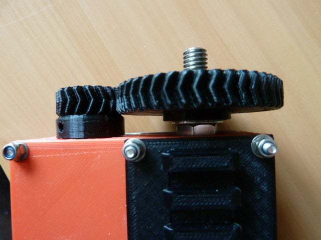
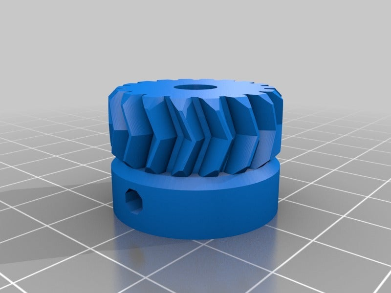
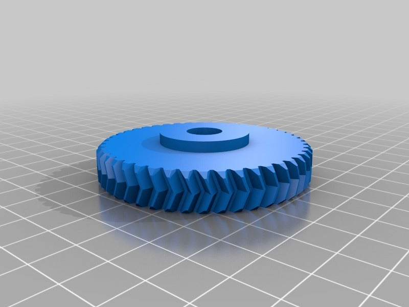
There are 18 teeth on the motor's gear, and 45 on the camera mount shaft
So, 1 revolution of the camera mount requires 200 x 99.05 x 45/18 = 49525 steps of the motor. Each step represents 0.00727 degrees rotation of the camera mount.
One siderial Earth rotation (which includes an allowance for the Earth's passage around the Sun) = 23 h 56 min 4s, which is 86,164,000 milliseconds. So one step requires a motor step pulse interval of 86164000/49525 = 1739.808 ms. My code gives a pulse of 1739.810 ms - near enough, considering the modest accuracy of the Arduino's pulses.
The period of rotation for star photography (sidereal time) is easy to find, but I had to do some research for the moon (to be precise, I asked my brother - a keen amateur astronomer). In the end I used 24h, 52m 48s for the moon and 24 hours for the sun, even though the latter does vary a little bit throughout the year (it is good enough for this project). Although I put exact values in the source code the Arduino is not super-precise in its pulse length, but it really doesn't matter while making exposures counted in seconds or minutes. However, any adjustments, changes or corrections are easy to enter into the spreadsheet, and the resulting calculated values can be transferred to the Arduino code.
Note: Having 3 different tracking speeds may be unnecessary - you may find that the default siderial time is more than adequate for most astrophotography!
IMPORTANT: 'Solar' is included for use with projection devices (e.g. projecting an image of the sun onto white card - see Solar Projection). NEVER LOOK AT THE SUN THROUGH A TELESCOPE - instant blindness would be the result. Aiming a camera at the sun could also be a mistake - a costly one - unless appropriate precautions are taken.
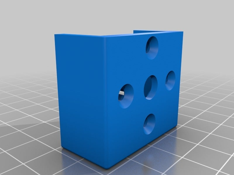
Physical design - Tracker Head
The tracker head is the heart of this project: it holds the motor, gears and camera mount shaft securely. In addition, it holds itself securely onto the top of the tripod, with the option of 1/4" UNC or 3/8" UNC threaded screws. You might need a longer screw on the tripod for 1/4" as they're usually quite short to avoid damaging cameras.
It has a 3/8" UNC threaded rod as the camera mount shaft because that is the thread size at the base of my camera's ball head. These ball heads often come with this size of thread, together with an adaptor for 1/4" UNC. If your ball head only has a 1/4" thread then you will have to adapt the design to use 1/4" threaded rod - this means different bearings, smaller recesses in the body and different-sized holes in the large gear for the rod and nut.
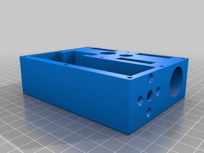
The body itself is straightforward, although it does take a fair amount of filament and a lot of time to print. The dimensions are those that worked with my own printer; because of this it is worth using the test files to ensure that the bearing, mounting nut and motor mount holes are correct before committing yourself to the 'big print'. Aim for at least 3 layers top and bottom, 3 perimeter vertical layers on the walls, and around 30% infill for maximum strength.
The motor has to be fitted in the correct orientation, otherwise the aluminium plate won't fit. Its wires should go sideways into the space provided, then round the motor base to the exit hole.
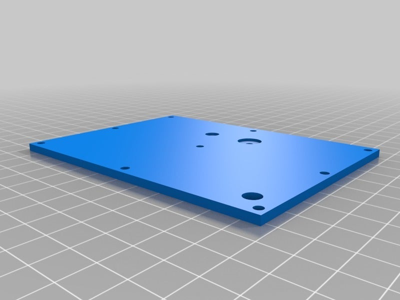
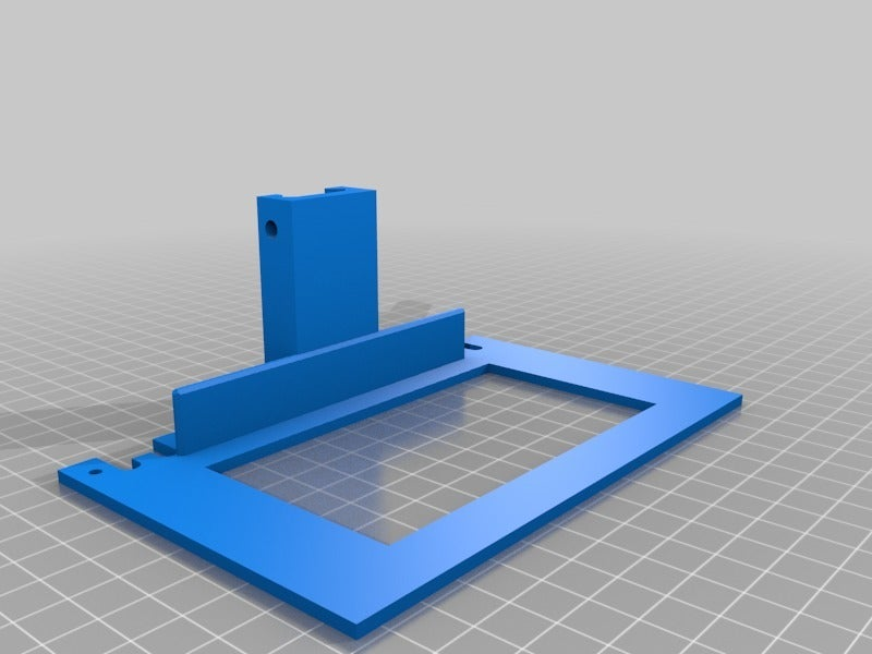
Note that I have used aluminium sheet as a base plate - this takes all the torque forces resulting from the weight of the camera, its ball head and the tracker head itself - a printed one would not be strong enough to survive. This plate takes a lot of strain away from the main body. The file tracker_head.scad can be used to create a drilling template for this plate (note that it prints upside-down); if you change the size of the body in the OpenSCAD code the template will be adjusted to suit. All holes in the template are the same size, so the pair of mounting holes will need to be enlarged to 1/4" and 3/8" respectively after drilling all of the holes with a 3mm bit. The template indicates which holes need to be enlarged. The screw holes are countersunk on the underside of the base plate (facing away from the body) to match the screw heads.
There is an optional picatinny mount that can be used for sighting devices - this could be replaced by a simple aiming telescope if required, but this mount is very adaptable.
Physical design - control box
Note that the control box has been revised and is now at V2: see the note at the end of the description to see a list of the changes.
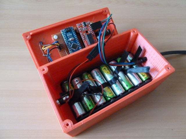
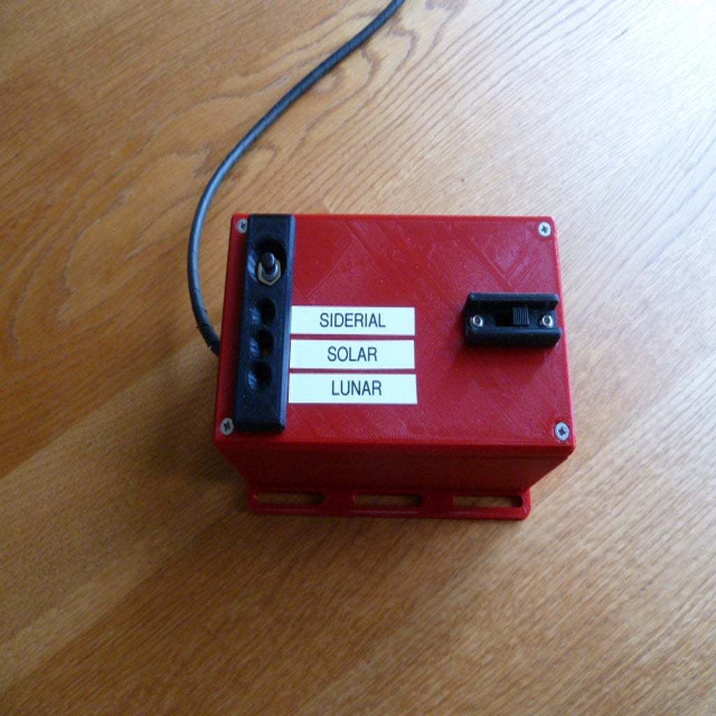
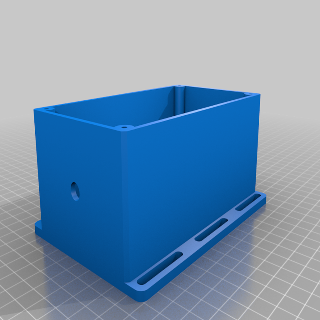
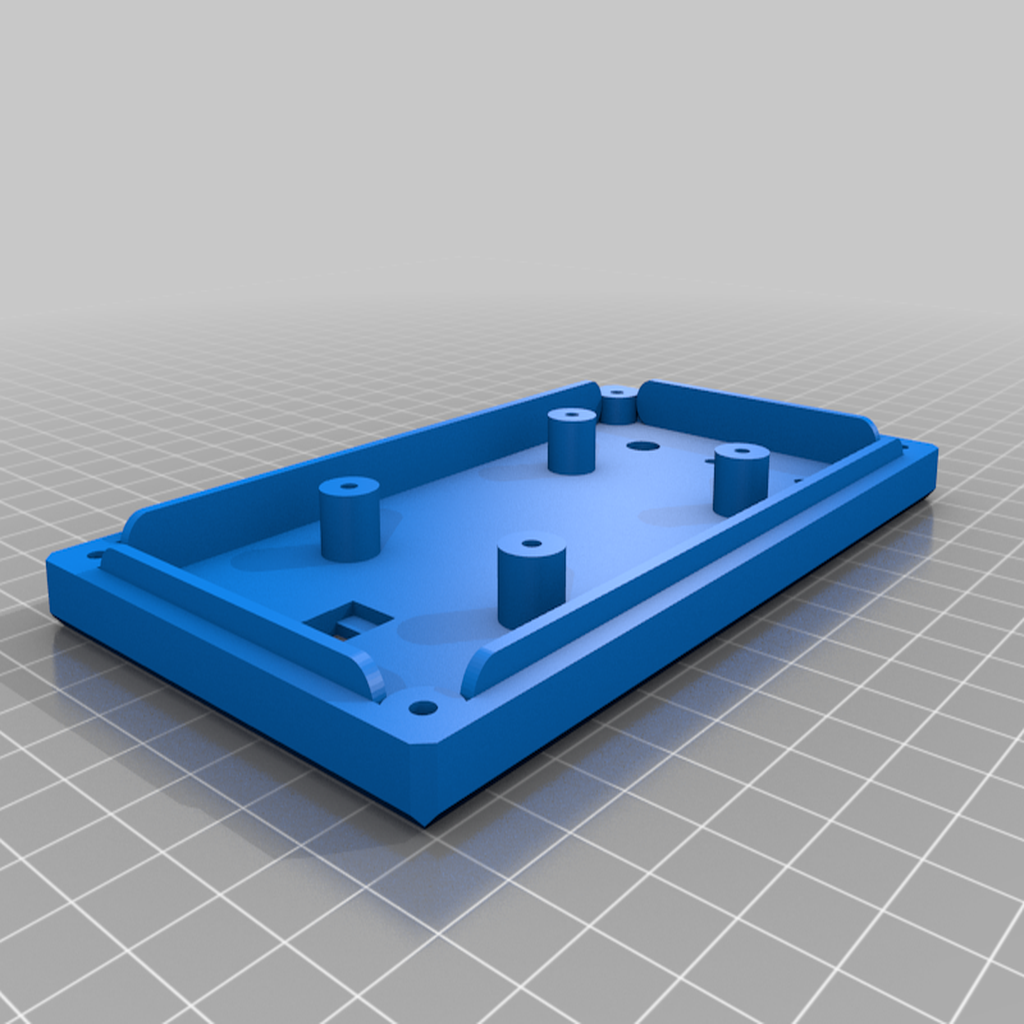
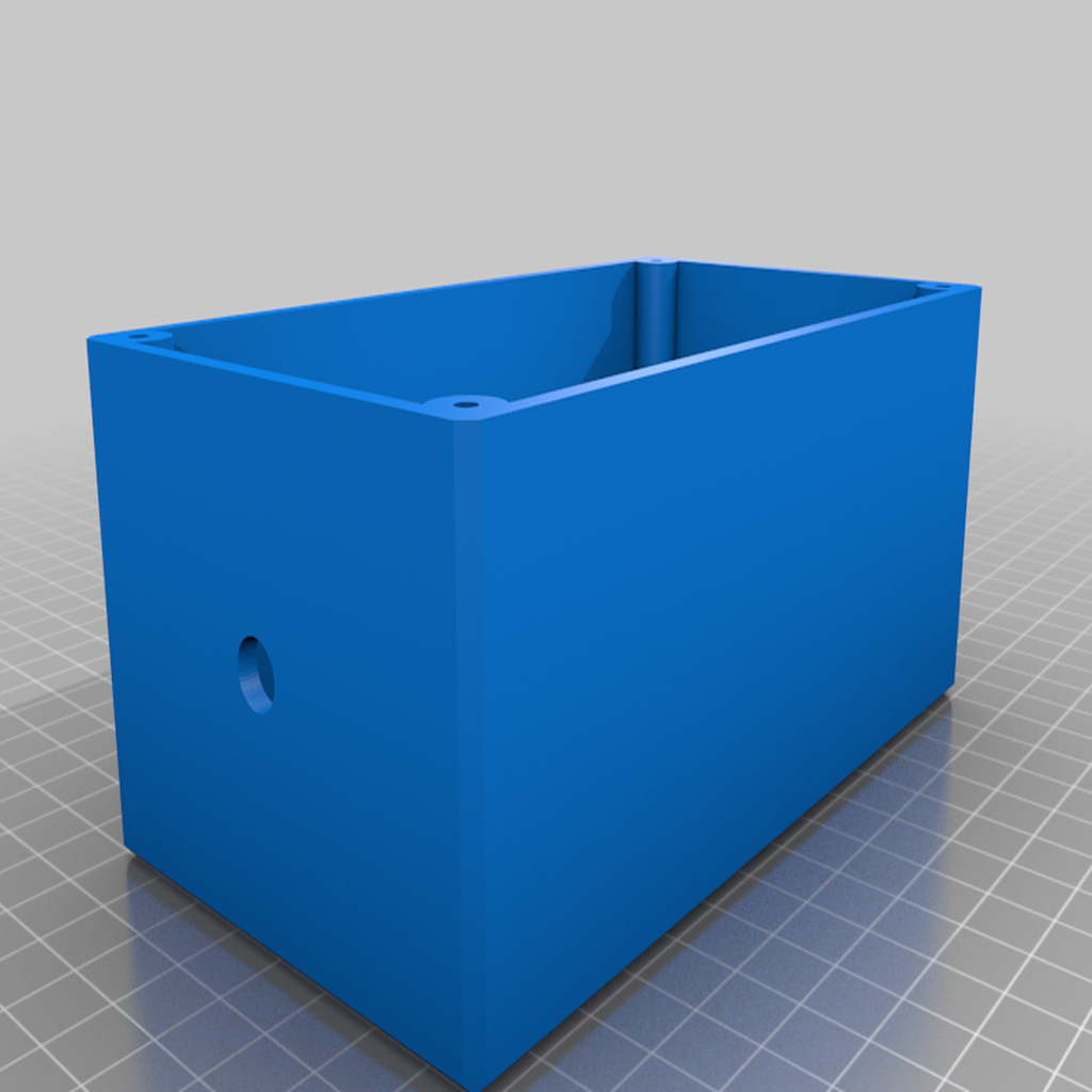
The control box is a simple design - the main characteristics that define its size are the battery box in its base and the veroboard holding the controllers mounted in its lid. The lid also holds the main on-off switch, 3 LEDs and a push button to select the required timing. The LED trim and switch guard are glued onto the lid.
It is also possible to make a sidereal-only lid for the box using an option in the OpenSCAD code (see update at the end of the description). This means that the circuit will only move at the sidereal rate, only one LED is required, and no push button.
Four short M3 nylon screws were used to hold the circuit board on to the lid - these aren't strictly necessary as long as care is taken to avoid short-circuits when using metal screws.
I used a set of 8 NiMh AA batteries in the holder, connected to a switched charging socket in the end of the box. Thin ribbon loops around each battery make it easier to pull them out, if required. The wires for the tracking head motor exit the box at the other end. Note: make the wires longer than I did - if you look at the photographs taken outside during testing you will see that I needed a table to keep the controller high enough to link up!
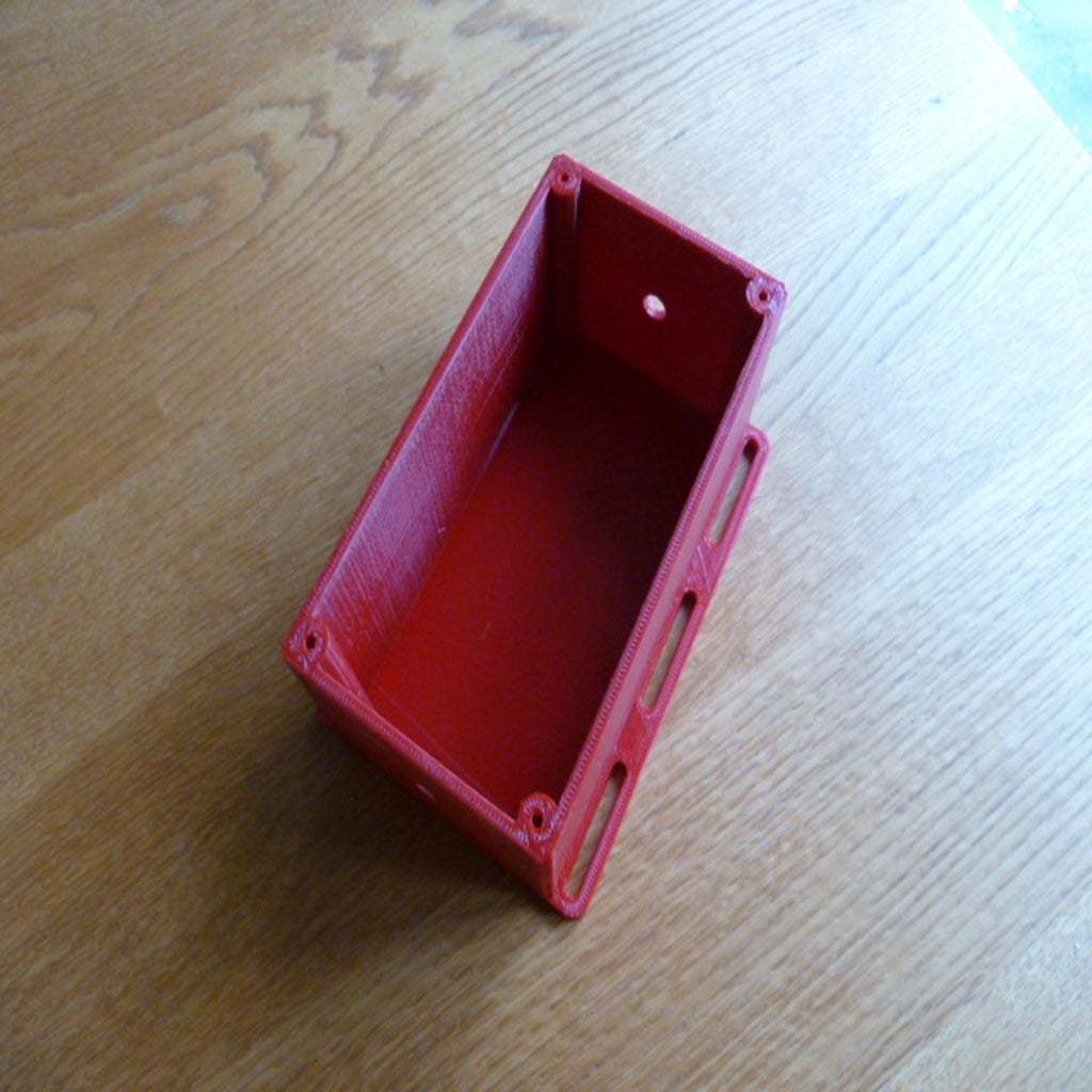
Version 2 of the box now has an option to add a mounting plate to the base of the box, so that it can be fixed to a tripod leg with velcro battery straps or similar.
Putting the theory into practice - the code
The spreadsheet was used to calculate the length of pulses required to turn the motor at the correct rate for a specific target. These values were used in the Arduino code (tracker.ini). I have tried to comment the code as much as I can, but ask in the comments if you have problems understanding what I've done (if I can remember the answers!).
My batteries (Eneloop equivalents) last about 3 hours, which is more than sufficient. However, the code also has a basic level of battery protection - if the measured voltage goes below a set level then all LEDs will turn on (unblinking) and the stepper motor driver will be put into sleep mode. It's not hugely accurate, but enough to avoid battery damage.
OpenSCAD requirements
Most parts will need to have the dimensions.scad file in the same directory, as that file contains variables common to many parts. You will also need slide_switch.scad in the directory if you are using that type of switch.
The following libraries will also be required:
Herringbone Gears: (by Frans-Willem Hardijzer)
Picatinny rail: (by Stuart Livings, Matthew Roberts).
Chamfers: Chamfer library (by 'SebiTimeWaster') - note that the file will need renaming to "chamfer.scad".
Circuit board
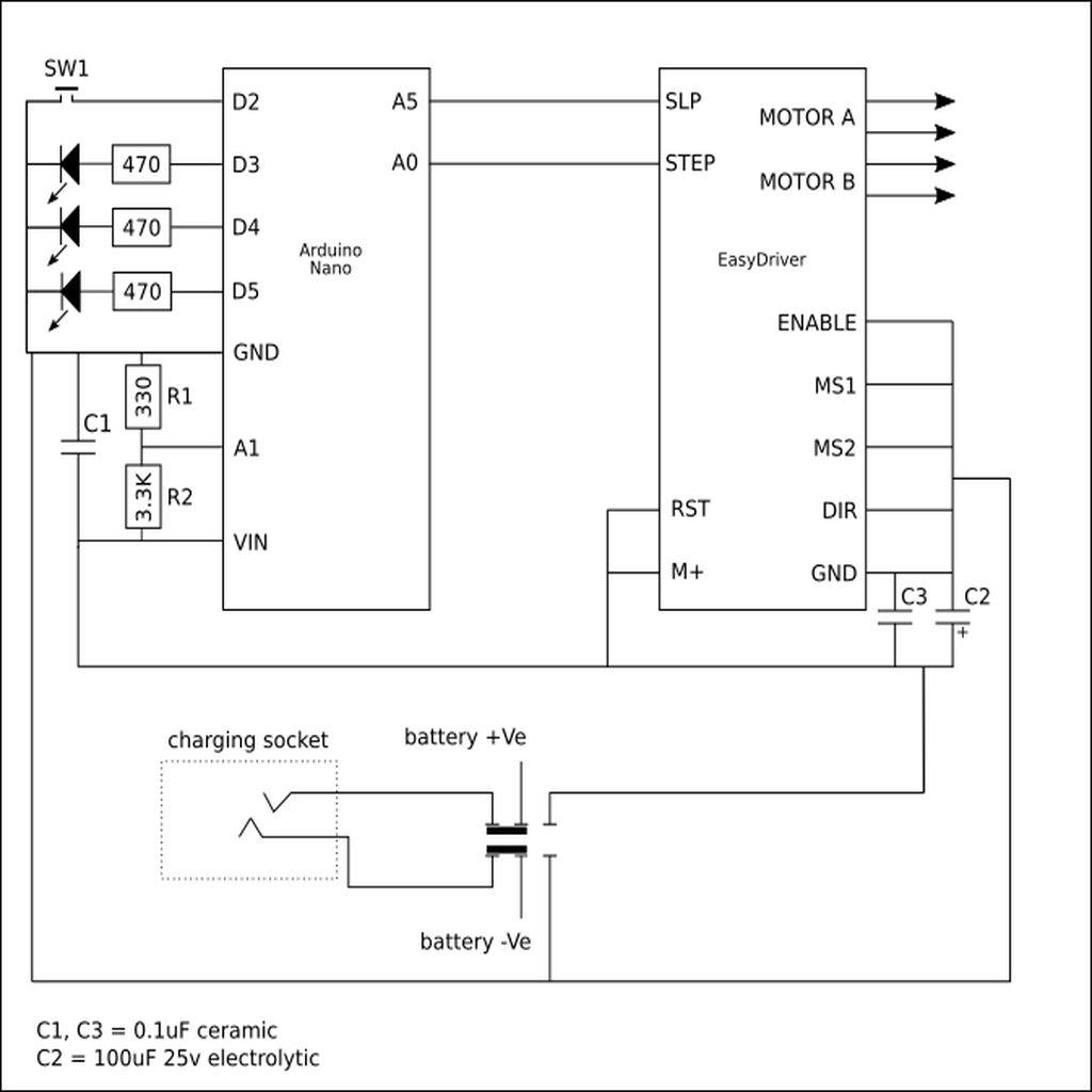
This was built using a piece of Veroboard, as it wasn't worth designing a PCB for a one-off project. I used single-row header sockets to hold the Arduino Nano and EasyDriver boards - note that I used strips that covered the whole length of the EasyDriver board. Right-angled and straight PCB header pins were used as appropriate (see pictures) for convenience. I also used R/C servo connectors to fit the header pins.
The layout diagram shows the view from the top: the copper strip cuts are on the underside of the board and tinned copper wire was used to make the links on the top.
Materials
Please note that all ebay links may fail in the future, as vendors change their listings.
100:1 planetary gearbox NEMA11 stepper motor
R6-2RS KLNJ 3/8-2RS sealed bearing 3/8 x 7/8 x 9/32 (2 required)
3/8" UNC stainless steel threaded rod (150mm minimum)
3/8" UNC stainless steel plain nut (3 required)
3/8" UNC stainless steel nyloc nut (1 required)
3/8" stainless steel washer
1/4" UNC stainless steel plain nut (1 required)
M3 x 40mm stainless steel countersunk screws (3 required if using the picatinny rail, otherwise 9 required)
M3 x 45mm stainless steel countersunk screws (6 required if using the picatinny rail
M3 stainless steel washers (9 required)
M3 stainless steel nyloc nuts (9 required)
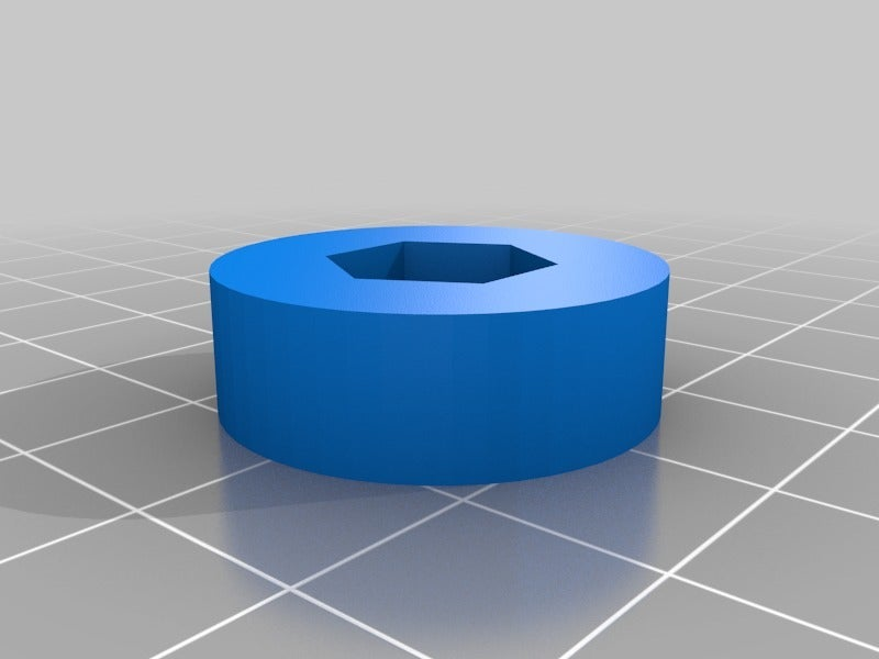
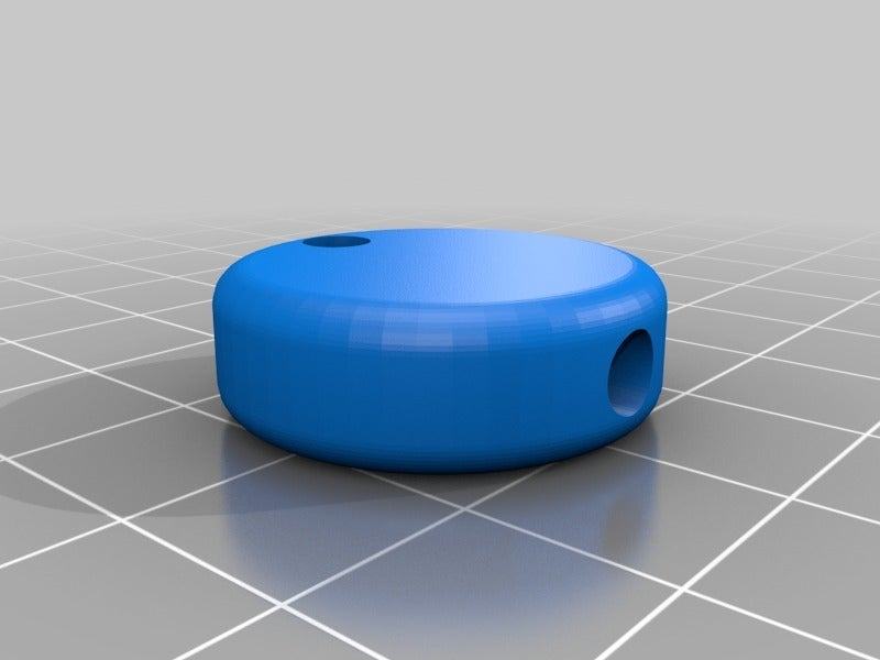
M3 stainless steel nut and grub screw (1 of each required for the small gear)
113mm x 85mm x 3mm aluminium sheet (may vary if the tracker head is modified)
Veroboard 18 strips x 26 holes
Header socket strip
Arduino Nano V3.0
EasyDriver Shield stepper motor driver
3mm LED (1 green, 1 yellow, 1 blue)
Small ceramic capacitors, 0.1uF (2 required)
Radial electrolytic capacitor, 100uF 25V (1 required)
Small resistors (1 of 330 Ohms, 1 of 3.3K Ohms and 3 of 470 Ohms)
Mini on-off rocker switch - no longer required for V2 lid
Standard-sized DPDT slide switch
Miniature push button switch SPST push-on momentary
8-way battery box
Using the tracker (and testing)
The first steps are straightforward: mount the tracker head on the tripod, attach the camera's ball mount, and connect the control box. When the controller is turned on a light will indicate that it's set to 'siderial time' (on my box, a green LED). Press the push button and it will change to solar time (yellow); press once more and it will change to lunar time (blue). One more press goes back to siderial time. The appropriate LED will flash at the selected pulse rate - but don't expect to notice any difference visually!
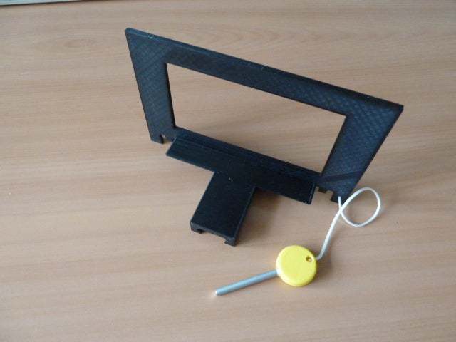
I added a picattiny mount to the top of the tracker to allow for aiming: at night I use a red dot sight to find Polaris (I know I need to 'aim off' a little to allow for precession). It is possible to use the sight by swinging the camera to one side, or the ball mount's quick release can be used to completely remove the camera while lining up. In the daytime it's not so easy - I tried to create a phone mount so that I could use Google's Sky Map to find Polaris, but my phone won't work accurately right next to a big fat magnetic motor. I have included the source file though, in case anyone wants to experiment, together with a peg handle that takes a length of 4mm rod - this holds the mount in place on the rail.
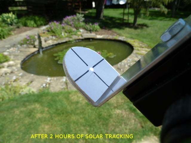
[UPDATED 21-June-2019] I have tested the tracker using the sun - I bent a simple aluminium bracket with a white card at one end and a pinhole at the other (see picture). The tracker head was set to the correct angle using a digital inclinometer (see photo), then the pinhole bracket was lined up so that the sun's white spot was central within the cross on the card. The sun's image was still central after 2 hours (again, see photo) so I can say with reasonable confidence that the system works and should be fine for astrophotography - now I need a good clear night...
[UPDATED 06-August-2019] I have added SCAD and STL files for an alternative lid, for those that only want to use siderial time (files all have 'siderial' in their names). I have also added files for an alternative single LED trim to use with this lid (optional). The code doesn't need to be changed as it defaults to siderial time until changed with the push button - if you don't fit the push button it won't get the signal to change. The single LED is connected via its resistor to D3 on the Arduino, and the others can be omitted.
Note that I haven't yet printed this alternative lid and trim, but there's no reason why they shouldn't work.
[MAJOR UPDATE TO CONTROL BOX 13-December-2019] I had been thinking that some aspects of the control box design weren't as good as they should be - then I made a stupid mistake so I had an opportunity to make the changes!
These changes are:
The original lid was an incredibly tight fit into the base and required some filing: now it should slide together straight off the printer.
I wanted to change the charging socket to a size that didn't match the input to my charger, to avoid accidentally plugging the power supply straight into the controller (yes, that's what I did and yes, I did fry my batteries). I couldn't find an alternative connector with a built-in switch, so I fitted a plain unswitched one and used a slide switch instead of the rocker switch.
There are so many sizes of slide switch that it was not possible to pick one standard and be sure that everyone will be able to buy one, so now there's an OpenSCAD library that just takes a few measurements and generates the holes in their correct places.
:format(webp)/https://fbi.cults3d.com/uploaders/15394319/illustration-file/6f199045-9f4a-4d4a-bd94-098df09cd153/complete.JPG)


/https://preview3d-images.cults3d.com/variants/459elkqvxuge86r1m0loqaszk0jb/9ce1a1278a90847fe525f7bdea66ae6081035e320afa813bf6efbbbe4c5d9f85)
/https://preview3d-images.cults3d.com/variants/dflrdg28rhif0idi1jzzvscx3n5w/9ce1a1278a90847fe525f7bdea66ae6081035e320afa813bf6efbbbe4c5d9f85)
/https://preview3d-images.cults3d.com/variants/vljx1odfqnwgjeqz291ca16ddt0k/9ce1a1278a90847fe525f7bdea66ae6081035e320afa813bf6efbbbe4c5d9f85)
/https://preview3d-images.cults3d.com/variants/g8feihsl0mbhqh6jdzsg7ts7kvly/2c25dfac9c0c4b3fee1a07527bd1c6bb2fb599b319b4e1ae3ef1d256f7781447)
/https://preview3d-images.cults3d.com/variants/n56869eemi51jh0vtx76my5mhp5n/2c25dfac9c0c4b3fee1a07527bd1c6bb2fb599b319b4e1ae3ef1d256f7781447)
/https://preview3d-images.cults3d.com/vmzn4zliw3qvup604nl2vdsq5kqs)
/https://preview3d-images.cults3d.com/variants/y70os4jn2pc0djv7ba67zdsagjn6/2c25dfac9c0c4b3fee1a07527bd1c6bb2fb599b319b4e1ae3ef1d256f7781447)
/https://preview3d-images.cults3d.com/9qiwjmnrzfopbkwjokc4v19oj0wc)
/https://preview3d-images.cults3d.com/variants/1xemx8dgbdjopjz81172w8oftcd4/9ce1a1278a90847fe525f7bdea66ae6081035e320afa813bf6efbbbe4c5d9f85)
/https://preview3d-images.cults3d.com/variants/4ptrkgxj8idhw0jbi0iophdbyeqp/9ce1a1278a90847fe525f7bdea66ae6081035e320afa813bf6efbbbe4c5d9f85)
/https://preview3d-images.cults3d.com/variants/dfrejulw1ow0539chbf7owr689dz/9ce1a1278a90847fe525f7bdea66ae6081035e320afa813bf6efbbbe4c5d9f85)
/https://preview3d-images.cults3d.com/variants/liy26ehxppg9n9i2ngd5cq329uny/9ce1a1278a90847fe525f7bdea66ae6081035e320afa813bf6efbbbe4c5d9f85)
/https://preview3d-images.cults3d.com/variants/nh4y2g1wvboiyzz90xlwfpq0lbou/9ce1a1278a90847fe525f7bdea66ae6081035e320afa813bf6efbbbe4c5d9f85)
/https://preview3d-images.cults3d.com/variants/r6lah6so04zwwguo8cf2qmnr2hcd/9ce1a1278a90847fe525f7bdea66ae6081035e320afa813bf6efbbbe4c5d9f85)
/https://preview3d-images.cults3d.com/variants/cvo8xt4oqeb5xm5twv6l2u18fa23/2c25dfac9c0c4b3fee1a07527bd1c6bb2fb599b319b4e1ae3ef1d256f7781447)
/https://preview3d-images.cults3d.com/variants/m4poxefou9kpol78vq4aghfkulr7/2c25dfac9c0c4b3fee1a07527bd1c6bb2fb599b319b4e1ae3ef1d256f7781447)
/https://preview3d-images.cults3d.com/variants/me2h9o1fahrlem9ky2aoeu76kpxy/9ce1a1278a90847fe525f7bdea66ae6081035e320afa813bf6efbbbe4c5d9f85)
/https://preview3d-images.cults3d.com/variants/irz6yvt7tzstwljm1icximrtoh5x/9ce1a1278a90847fe525f7bdea66ae6081035e320afa813bf6efbbbe4c5d9f85)
/https://preview3d-images.cults3d.com/variants/onfb2bzyqdd4ifbcbhfjmmj665rm/9ce1a1278a90847fe525f7bdea66ae6081035e320afa813bf6efbbbe4c5d9f85)
/https://preview3d-images.cults3d.com/variants/pmfiiqpeje3s07m1211s3zed2pq2/9ce1a1278a90847fe525f7bdea66ae6081035e320afa813bf6efbbbe4c5d9f85)
/https://preview3d-images.cults3d.com/variants/vuprjktu0zd8farchnc0a4rnupxy/9ce1a1278a90847fe525f7bdea66ae6081035e320afa813bf6efbbbe4c5d9f85)


