Skip to content

Tactile illusion via tangential skin strain

Advertising
Advertising
?
Creation quality: 5.0/5 (1 vote)
Evaluation of members on the printability, utility, level of detail, etc.

  • 1.1k views
  • 6 downloads

License
3D design format
STL Folder details Close
  • TactileIllusion_rePeintre.stl

Learn more about the formats

3D model size X 60 Γ— Y 64 Γ— Z 7.5 mm
Last update 2020-09-05 at 17:17
Publication date 2020-06-23 at 13:18
Design number 163011

3D printer file info

3D model description

Implementation of the tactile illusion described in the following publication:

Masashi Nakatani, Akihiro Sato, Susumu Tachi, Vincent Hayward. Tactile illusion caused by tangential skin strain and analysis in terms of skin deformation. Proceedings of Eurohaptics 2008, LNCS 5024, Springer-Verlag, pp. 229-237.

You can download the scientific article here:

https://www.researchgate.net/publication/221011688_Tactile_Illusion_Caused_by_Tangential_Skin_Strain_and_Analysis_in_Terms_of_Skin_Deformation

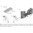
I have attached Figure 1 from the article, where it explains how the illusion works. Do the following:

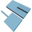
1) insert the protruding element into the receiving element;

2) place your index fingertip on the rugged region in the middle, while holding the non-rugged square nearer to you with your thumb and middle fingers;

3) slide the element further from you back and forth, using your other hand.

As you do this, you should feel either a bump or a groove under your index finger, depending on which element is oriented towards you and which one is oriented away from you. This means that, if you feel a bump, you should then be able to rotate the device by 180 degrees so that you are now sliding the other element, and you should feel a groove. Try it!

3D printing settings

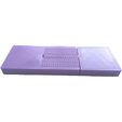
I printed this object using a Flashforge Finder with a 1.75mm filament at a resolution such that it took about 2 hours to complete the job. Extruder temperature was near 210 deg C. You should use a resolution that is sufficient to render the rugged region in the middle of the device adequately. The object is designed to be printed at a magnification such that its shorter side is 30mm. I have played around with the size of the protruding element to ensure that it would snugly fit into the receiving element, at least for the printing specifications I used. It is important that the fit is snug in order to obtain a good illusion.

Advertising


Issue with this design? Report a problem.

Would you like to support Cults?

You like Cults and you want to help us continue the adventure independently? Please note that we are a small team of 3 people, therefore it is very simple to support us to maintain the activity and create future developments. Here are 4 solutions accessible to all:

  • ADVERTISING: Disable your banner blocker (AdBlock, …) and click on our banner ads.

  • AFFILIATION: Make your purchases online by clicking on our affiliate links here Amazon.

  • DONATE: If you want, you can make a donation via Ko-Fi πŸ’œ.

  • WORD OF MOUTH: Invite your friends to come, discover the platform and the magnificent 3D files shared by the community!


Sharing and downloading on Cults3D guarantees that designs remain in makers community hands! And not in the hands of the 3D printing or software giants who own the competing platforms and exploit the designs for their own commercial interests.

Cults3D is an independent, self-financed site that is not accountable to any investor or brand. Almost all of the site's revenues are paid back to the platform's makers. The content published on the site serves only the interests of its authors and not those of 3D printer brands who also wish to control the 3D modeling market.

100% secure payment by credit card, PayPal, Apple Pay, Google Pay, etc.
View all payment options.