See it working here: https://youtu.be/vKAmmksFpJ4 and here https://youtu.be/mn-dIP0MK7c
30-12-17 IMPORTANT SAFETY TIP - I HAVE NOW ON TWO OCCASIONS HAD THIS PRINTER TIP OVER, ITS TALL AND NARROW. PLEASE SECURE THE PRINTER TO THE BATTERY UNIT WITH THE SCREWS (IF USING LIPO BATTERY). PLEASE ALSO CONSIDER SOME OTHER FORM OF RESTRAINT. IT SEEMS TO BE THE WEIGHT OF THE SPOOL WHEN FULL ON TOP. I WILL DESIGN A NEW SPOOL HOLDER.
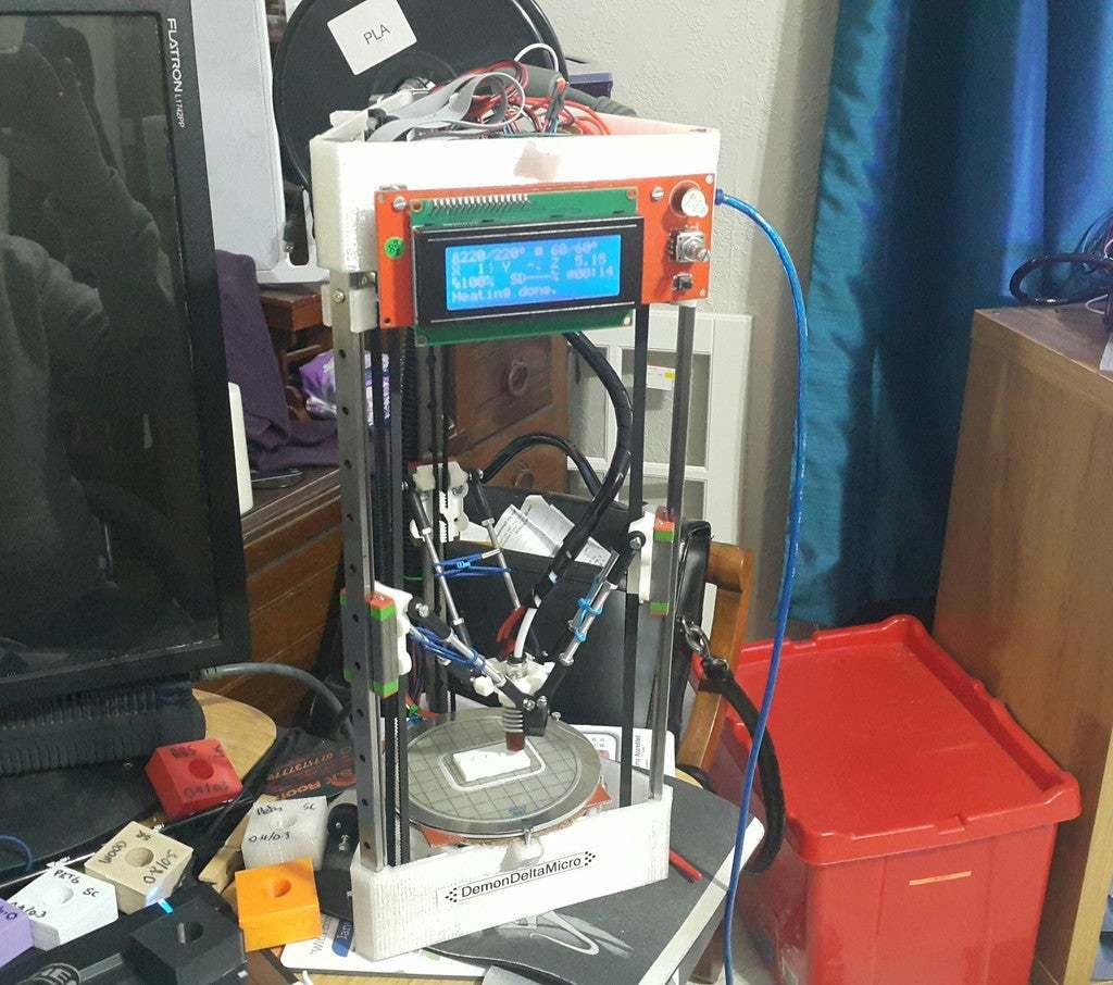
Update 15-09-17 - DemonDeltaMicro goes fully portable!
Okay, so can you make a portable 3D printer which runs off lipo batteries - yes.
I have made an add-on module for this printer which allows truly wireless, portable use.
https://www.thingiverse.com/thing:2536426 I have also added a modified base for the printer which allows you to attach the battery module.
Update 22-07-17, so the Micro has finally got a z-probe, please see https://www.thingiverse.com/thing:2446460 now calibrating to 0.07mm deviation using RC's marlin and the Precision Piezo, Z-probe system.
Update 11-07-17 Decided to try a new heater for the bed. Keenovo (eBay and Aliexpress) offer custom heated bed this size for only £25 delivered to UK. So I opted for a 100mm diameter silicone heater at 50w 12v (4 amps) so it should heat up quicker, be neater and fit better than the square (off the peg) heater that I had before. The quality of these units is excellent, and you can specify the thermistor/pt100 sensor etc.. you want when it is made.
Also moved on to using LV8729 drivers which IMO are very good, they are much quieter than A4988's and although they are specc'd for 1.5A max this is ample for a micro/small printer. Unlike TMC 2100's they are stable, and run cool.
Update 24-04-17 Gone back to the A4988's as the TMC's were just too difficult to tune, working well one minute and layer shifts the next. Also changed the unbelievably noisy fan on the mini hotend for a Sunon Maglev 25mm fan, which is much quieter.
Update 07-04-2017 - recently swapped my A4988 drivers for TMC2100's. Its early days but the improvement in terms of noise from the motors is quite substantial. I've set the vref for 0.6v on x,y,z and 0.7 on e. However the x,y,z motors run quite hot so I am thinking about experimenting to see how much lower the current can be set to find the optimum between performance and heat. Turns out 0.5v for x,y and z seems to give good print quality, low noise and only warm motors!
Update 18-03-2017 So I'd been having spurious power issues for quite a while, seemingly power levels falling to just below the point where things start to go wrong, layer shifts etc.. I found out it was the main power connector on the ramps board failing to make a solid connection. Luckily with this printer the power requirements of the heated bed and hotend are quite low so fire risk was less than it would be for a larger machine. So I have fixed the offending power connector and this issue has been resolved.
Update 28-02-2017 - 200 downloads - this is great, but still no makes? Has anyone made one or is mine the only one out there?
Update 05-02-2017
So I had been using this for a while using marlin rc8 but was never totally satisfied with the calibration as even these latest versions of marlin do not allow a full range of delta calibration parameters.
So I "downgraded" to Rich Cattell's Testing version of Marlin and then used the Escher3D manual calibration page as detailed below and got a perfect calibration. A preconfigured version of this firmware is downloadable here: https://1drv.ms/u/s!Apv79JfGbPIwgu4G3YxY8hYodZkAgg
Please carefully check the configuration especially for manual_z_home position i.e. z height, and print radius. Then beginning with the values in the log.txt file calibrate it manually and use the generated M666 command from escher 3D page (make sure to select Marlin Rich Cattel) and send and m500.
Also I was getting intermittent low power conditions, so I reworked the wiring from the XBOX PSU. I have added an image to the photos zip file I'm hosting at https://1drv.ms/u/s!Apv79JfGbPIwguhAdgJB9SedYitGhw basically put all three yellow wires together, all three black wires, then distribute positive and negative to the ramps and accessories. The issue was with 1 rail to the heated bed (not very powerful) there wasn't always enough power on the other two rails to run everything else.
Also slightly adjusted the carriages (v1.1 uploaded) as the belt rubs on it. I just applied a little grease to the back of the belt for now will reprint the new carriages if I need to later.
Update 28-12-16
100 Downloads! Awesome. Please let me know if anyone makes one and how you got on with making it, and what you changed or improved. Have a happy new year all. The printer is working well and has been printing parts for its Kossel XL stable mate.
Update 20-12-16
So after switching the max PWM back to 255 for the hot end heater I was running into a problem of not enough power on the 5A connector (for motors/hot end) as I only connected 2 of the 3 rails from the xbox supply, one to 5A and one to 11A. The motors were pulsing a bit and the display dimming when the hot end was heating. As such I was skipping steps and having problems. So connect one rail from the xbox supply to the 11A ramps connector (nearest the centre of the board) for the bed heater, and the other 2 rails joined i.e. 2 yellows (+ve) and 2 blacks (-ve) to the 5A connector which is towards the outside of the board, to power everything else.
I also did away with the bed clamp printed parts they were too flimsy and instead used some wide m3 washers to hold the bed instead.
Update 17-12-2016
I was having two issues. The first was not getting the hotend to the correct temperature very smoothly. I decided to switch max PWM for hotend back to 255, which mean it now heats up in under a minute, it will oscillate for a 20 seconds or so before stabilising, it is a very small mass on the mini hotend compared to an e3d with a large heater block.
Also the 60mm fan is very powerful and can cause heater errors by overcooling the hotend, so I have used a fan max speed in slic3r of just 30%, and minimum of 5%. This seems to be more suitable.
Update 10-Dec-2016
So decided to add a fan for cooling the print, normally I'd go for a dual fan on the effector, but I haven't got the space, so instead I've fitted a 60mm 12v fan to the side of the bed, slightly angled upwards in the hope it might cool even a tall print a little bit. This most likely need to be used on a low setting to not overcool the bed or hotend. Connected to D9 mosfet output on ramps.
Also wired the PSU properly with the blue xbox PSU wire to PS-ON and red wire to VCC. Now with the addition of M80 in my start gcode to turn PSU on, and M81 in my end gcode to turn it off, I don't have to listen to the really noisy fan on the mini hot end when the machine isn't printing. If doing this its a good idea to use M109 R40 to cool your hot end and wait for it to stabilise, before doing a PSU off to prevent filament jamming in the hotend during cooling. Also set PSU to 2 in Marlin to enable PS-ON to switch PSU.
Update 6-Dec-2016
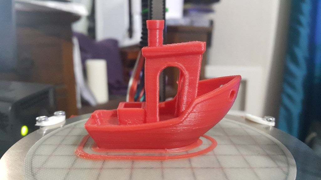
Uploaded some images of prints, these are the 6th, 7th and 8th objects the machine has printed and are printed in ABS but with no layer fan at all, I'm still working on that. With other printers I have built there would be weeks of tuning to get these sort of results, so either I have been lucky in the build or this machine is quite capable straight out of the box, so to speak.
Update 4-Dec-2016
Bed clamps now working, slightly awkward if using a square silicone heater as it sticks out and interferes with them, try to use a round 100mm silicone heater if possible.
If you need a thermistor table for the Deltaprintr Mini hotend for marlin I have made one, and included it in the sample firmware its table 14, in thermistortables.h, just set #define
TEMP_SENSOR_0 14.
I removed the photos as I think I hit Thingiverse limit on number of attachments for one listing they can be downloaded here:
https://1drv.ms/u/s!Apv79JfGbPIwguhAdgJB9SedYitGhw
Update 3-Dec-2016
-Had to turn the extruder motor to 0.9v to get reliable extrusion.
-Got rid of the spring from the extruder, just tightened the idler bolt on tight.
-The tower motors are warm in use at 0.6v but not too hot to touch.
-Deltaprintr mini hotend came with no instructions, but seems easy enough. The stiff wires are the heater, then a thermistor and a fan. Not sure if the fan is 12v it's quite noisy but the heatsink is cool.
-I'm using thermistor table 6 which seems reasonable at 200-260 deg C but I might generate a new thermistor table for it.
-I've turned down max pwm for hotend to 160 as it was overshooting at 255, it's quite a small heater.
-Given up on the spool holder I designed, it was large and awkward and decided to go with one by goldengears5 (http://www.thingiverse.com/thing:1132828) which I have modified slightly (not very well) to fit the brackets on the top triangular section with some stand-off's.
Overview
So my 3D printing journey has taken me from fixing up an old Prusa I3, to buying a Kossel Mini and tuning the hell out of it, to enlarging and enclosing a CoreXY built from a kit, to self-sourcing and building an all metal XL Kossel. What's left? Designing my own printer and here it is.
Design philosophy.
I wanted to make a micro sized delta. Since we are often told that accuracy and reproducibility is harder with larger machines, it should be easier with small ones. I love delta's, they have a lot going for them, small footprint, great packaging - all the parts can be contained within the base and top, the motors are stationary, the print bed is stationary. They do have some drawbacks calibration and setup is more challenging the motion for x, y and z is derived from positions of carriages on towers, all three of which must be perfectly aligned to move exactly to position the effector/nozzle where you want it. They frequently use Bowden extruders to keep the mass on the effector low, if long tubes must be used, filament control suffers, but keep them short and tune them well and print quality can be reasonable. The flying extruder or a flexible driveshaft extruder is best but for this tiny printer I just don’t have the space.
I wanted to make a machine that can fit on any desk. The small print area reflects the fact that a large proportion of items commonly 3D printed are small. I wanted to have a good range of materials printable so a heated bed is necessary. Future releases will possibly include an enclosure.
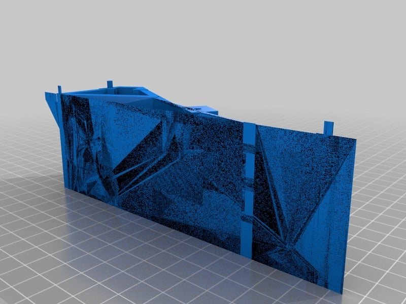
The other desirable feature is to make the machine simple. As such the bottom triangle and upper triangle are one piece units and 3D printed. You'll need a large(ish) printer to make them, and PETG is preferred for its strength and slight flexibility, so an enclosed chamber might be necessary. The vertical frame components are only the steel linear guides, for simplicity. The linear guides (and maybe motors) are the only expensive component. I've specified nema 14 motors which should be sufficient to drive a machine this size. Initially using ramps/Arduino mega as I have one lying around and it's small, annoyingly the controller is still too large for the space, but I cut away some of the sides which will also help with ventilation. A fan can be added here to cool the electronics.
The power supply must be an external unit - I have an x-box PSU lying around and these can be had for £10 on eBay. 12A @ 12v should be plenty.
The machine will have a heated bed, I am trying a 40w 12v silicone heater. This ensures a wider range of materials can be printed. The bed will be fixed. With such a small size, it does not seem necessary to use probes. With such a small bed achieving flatness is much more likely without spending money on machined tooling plate. As such manual calibration will be necessary, but using DC42's least squares calibration calculator makes this easy enough to do.
I am going to try the mini hot end from Deltaprintr, it seems to suit the style of the machine and its small size will allow a little more z height. However, you could attach an E3D v6 or similar at the loss of perhaps 15-20mm of z height, and a modified effector would be needed.
I am currently using a simple printed extruder driven off a geared nema 14 motor, but use a nema 17 of you have one lying around.
The linear guides will provide very smooth, lash/backlash free movement of the carriages. The arms are for the time being aluminium m4 threaded rods and RC car type ball joint ends.
I have also set about seeing if I can design this printer in Tinkercad. I am not a trained CAD person, but I manage to make things using Tinkercad. The beta version allows for a more precise build with much better and easier to adjust parameters for objects. I fully expect someone with real CAD skills will revise this into a more polished version using better CAD software. Please do, and let me know.
In order to further simplify the design the idlers for the belts will be attached to the bolts holding the upper frame, which also hold the endstops which are simple micro-switches, no levers and using only the NC contacts, for fail safe operation.
I have initially configured Marlin RCbugfix (shortly to be marlin 1.1.0), which I will make available as a starting config but you must customise anything you have changed, and calibrate the machine, I used the least squares calibration tool at escher3d, which seemed to derive a solution with little difficulty.
You are free to modify or remix this item but please attribute me for the original design.
I have remixed and used the following items, and I am extremely grateful to their designers for their skill and innovation.
Effector http://www.thingiverse.com/thing:731354 - thanks to saldot
Extruder http://www.thingiverse.com/thing:1308189 - thanks to hholweger
Filament guide/cleaner http://www.thingiverse.com/thing:322952 thanks to vyndalin
BOM - subject to change
Frame
2x printed triangular sections
3x MGN12H linear guides 40cm - but you could use 35cm and make it even smaller, with 35cm guide you only get 70mm z height. (Chinese ones are fine just clean/lube them well)
12xm3 x15 machine screws
12xm3 nyloc nuts
These bolts are optional if you want to screw the guide to the frame, they are interference fit if frame made in petg, you could add a little adhesive, once sure the frame is square.
Drive system
3x Nema 14 motors 1.0A type
3x 16t 5mm shaft drive pulleys
3x flanged idler gears
6xm3 nyloc nuts
6xm3 A2 washers
1.8m of gt2 belt
3 printed carriages
1 printed effector
6x arms (either RC car rod ends traxxas or similar plus threaded alu rod, or carbon tube)
Bed
120mm diameter aluminium disc 3mm thick
120mm print bite/PEI sheet with adhesive
100mm silicone heat mat 12v 40-60w ideally circular but square works
with adhesive such as 3M 468P/300LSE
3x m3x20 bolts
3x m3 nuts
120mm circular sheet of cork+cardboard
Extruder - use whatever you prefer, if you want to use the same as I have here:
1x printed extruder and idler arm
1x nema 14 5:1 planetary geared stepper.
1x mk8 style drive gear (or other if you prefer) drilled out to 6mm for gearbox on motor
1x608zz bearing for idler
1xm3 machine screw
1xm3 nut
1 spring to fit m3 bolt.
thread on bowden coupler standard type
Electronics
1x 12v external PSU approx. 150w (I intend to use x-box original PSU)
1x arduino mega+ramps 1.4
3x NC microswitches maplin type N95AQ
6x m2 x10mm machine screws for microswitches
1x mini hot end (Deltaprintr - but you could use any hot end you wish)
various wire/solder/connectors.
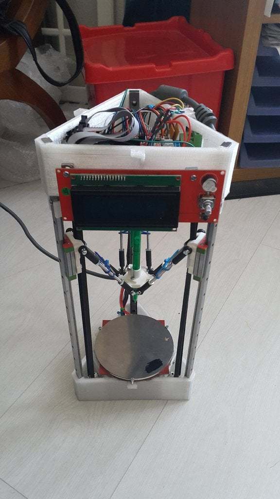
I have configured it for motors at the bottom, to make it more stable with a lower centre of gravity, and electronics in the top section. It is possible to configure it the other way around.
My sample preconfigured Marlin firmware is here: https://1drv.ms/u/s!Apv79JfGbPIwgug5fQX4CDcU-42Chg
A set of photos showing the various areas to help you build it is here:
https://1drv.ms/u/s!Apv79JfGbPIwguhAdgJB9SedYitGhw
Build Instructions
Print/get printed/buy the parts.
Whilst this is not commercial, if the design seems reliable, I can print some of the PETG top and bottom sections on my enlarged corexy, order them via my 3dhubs page. https://www.3dhubs.com/bristol/hubs/demon3d-kingswood
Upper and lower horizontal sections in PETG. Extruder in ABS/PETG. Everything else in ABS.
1) De bur any sharp bits/blobs/strings from the top and bottom printed horizontals. Decide on whether you want the motors at the top or bottom. The rest of this guide refers to motor section at the bottom and electronics section at the top.
2) Clean and lubricate (lithium grease or 3in1 oil) your linear guides, if notchy then check the bearings are all present, there should be a gap of 1 bearing width in the row of balls. Be careful not to allow the carriages to slide off the rails unless over a tray, or very gently as bearings may escape and are hard to find. If you need new bearings measure a few with calipers to ensure you’ve got the correct size and buy some, they might have to be imperial sizes.
3) Push by hand (its a tight fit) the three linear guides into the slots at the corners of the lower section with the metal carriages facing inwards. Using a rubber hammer or metal hammer and piece of wood to cushion the impact, tap the linear guides completely into the bottom section preferably on a hard surface so they stop cleanly when inserted. They should be roughly at 90 degrees to the lower section.
4) Now position the upper section over the 3 guides and position them into the slots. Using your hammer tap the upper section down onto the 3 guides a little at a time going around each of the three corners with gentle taps each time. Eventually the upper section will have the guides fully inserted so that they are flush with the top of it.
5) Check if the linear guide rails are 90 degrees to the lower section using a set square, 1 degree out might be okay much more than this and something has gone wrong.
6) Attach the three nema 14 motors to the bottom section by pushing their shafts through from inside to outside, sliding the 16t drive pulleys onto the shafts as you do it. Position the grub screws on the pulleys towards the motor. don't do them up yet, you need to set their position when belts are attached to ensure belts run smoothly. The motor needs at least 2x m3 hex bolts to fix it in place. Use proper bolts not machine screws there is very little space to do them up.
7) Take three microswitchs and snap off the central electrical tag, which is the NO contact, it will get in the way and we aren’t using it. Attach a microswitch to an endstop holder with m2 screws. They should bite into the plastic the holes are 1.8mm.
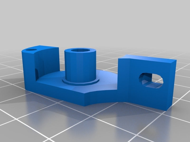
8) Select a hole in the linear guide just below the top section with around 5mm of clearance above it. Take an endstop holder and an m3 x40 machine screw. Place the screw through the linear guide from the outside, on the inside place the endstop holder over the screw and push the endstop holder around the linear guide. Secure with an m3 nut. Now placed an m3 nyloc nut with the nylon-side-first onto the screw, screw it almost all the way to the endstop then an m3 washer, then the idler pulley, then another washer and a final nyloc nut the normal way around. Don’t overtighten onto the pulley as this will prevent the bearing from working normally. You might have to move the pulley position depending on the belt. Now repeat for the other two corners.
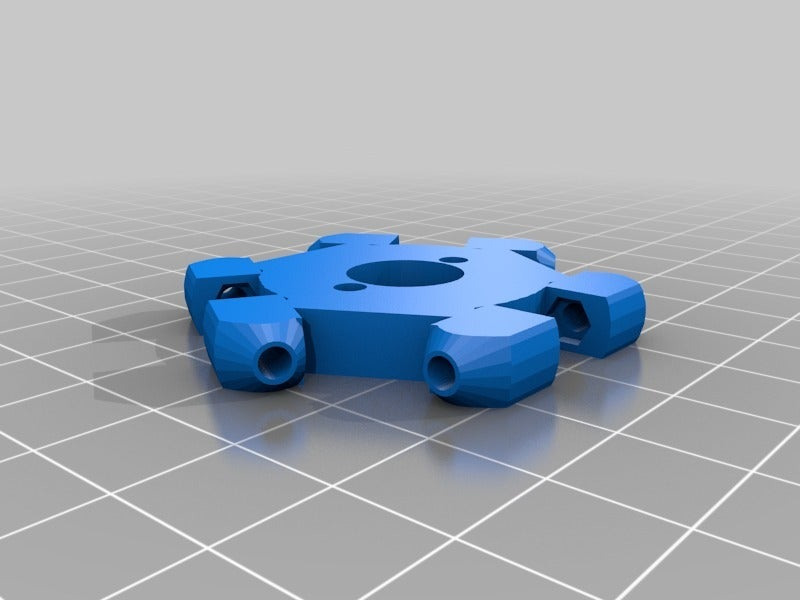
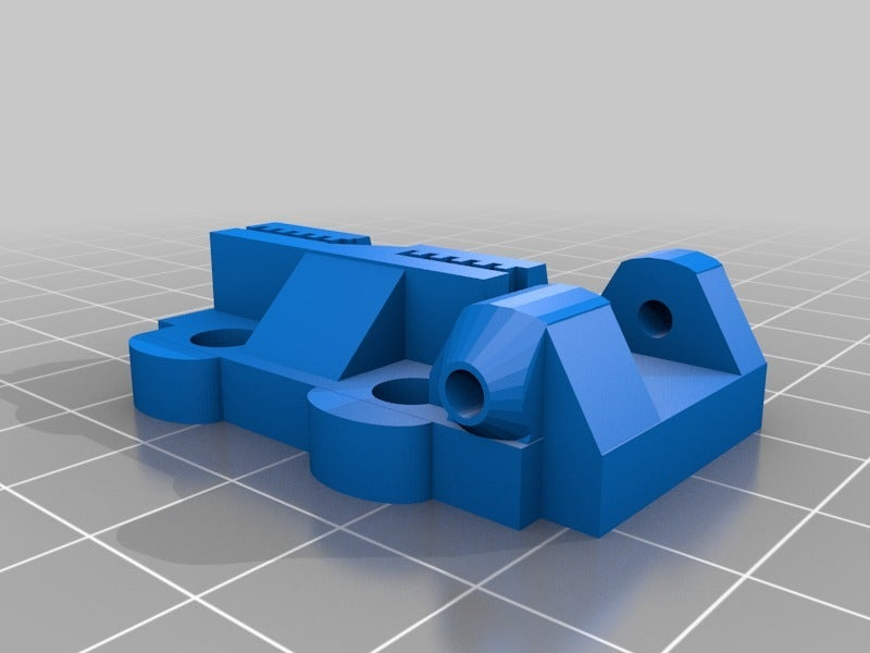
9) Attach the printed carriages to the metal linear guide carriages, use at least 3 machine screws per carriage (4 is unnecessary, but use one if you wish), ensure each carriage fits snuggly and without any significant space between it and the metal carriage underneath. It must not be, even slightly rotated, angled etc... Each carriage should fit in the same way as the other two. Ensure the mounting points on the sides for the arms are at the top. Do not use over long machine screws, they will interfere with the bearings in the linear guide carriages.
10) Belts - cut approximately the right length of belt off the roll, allowing a little extra. Attach the belt to the belt clip in the upper half of the printed carriage, then run it up and over the idler pulley at the endstop holder, then back down through the left side of the carriage, around the motor pulley, then back to the printed carriage where it should be attached so that it is reasonably tight. Cut any excess off, so that it doesn't interfere with the unattached section of belt nearby. Repeat for the other two towers. Now ensure the drive pulleys on the motors and idler pulleys at the endstops are positioned to allow the belts to travel with as little interference as possible. You must get very close to the endstop switches to achieve this. Tighten the grub screws on the drive pulleys appropriately.
11) Arms. It is imperative that each pair of arms are as close to the same length as one another as possible and that they are light. Basically, try to make all the arms the same length. One of the STL's is a jig. Print it and push m3 bolts through the holes. I made my arms by cutting a 500mm M4 aluminium threaded rod into 6 equal lengths, put nuts either side of each cut to debur the threads after cutting. I bought 20 rod ends for RC cars from ebay, discard the 8 which have the most play in the joints.
Now screw the aluminium rod (with two nuts threaded on it first), into the rod ends until you have approximately equal amounts of thread in each end and the rod ends fit over the m3 bolts in the jig. Tighten the nuts against the rod ends. Make 5 more. If you prefer cut carbon fibre 4mm rod into 6x83mm lengths and use the jig and epoxy to bond the rod ends on.
12) Attach the rods to the carriages with m3 bolts, the bolts should bite into the plastic. I have scaled down the carriages and effector so the nut traps are not sufficient size for nuts, although the holes are 2.8mm to allow self-tapping. Attach the arms to the effector in the same way. The effector should be reasonably stable, but attaching some elastic such as hairbands between each pair of rods to pull them towards each other removes play from the ball joints and makes the effector more stable.
13) Construct your extruder as per relevant instructions. If using the one I am using, all you must do is screw the motor to the extruder body. Attach a drive pulley, attach the idler arm, press a 608zz bearing onto it, and attach an m3 nut, m3 bolt with spring over it, and screw in the bowden coupler. In PETG the parts will stand up to having metal screwed into them quite well. Any holes which are too tight lightly drill them if needed. I attached the extruder to the side of the top section by drilling to mounting holes and using m3 nuts/bolts.
14) Attach your ramps board to the top section with m3 bolts/nuts. Cut out are provided for the power connector, usb cable and on the left side a 40mm fan to cool the electronics. If using an LCD display such as reprapdiscount smart controller I drilled two holes and mounted it to the front of the upper section with m3 screws. You might have to drill the PCB to make the holes closer together, this is okay as the majority of the PCB is the ground plane both sides.
15) On the xbox PSU, cut off the connector (after ensuring its powered down and discharged). Join the blue and red wires together and insulate them. Now connect 1 yellow (+ve) and 1 black wire (-ve) to each rail on the ramps board, saving one rail for a spare (insulate these cables).
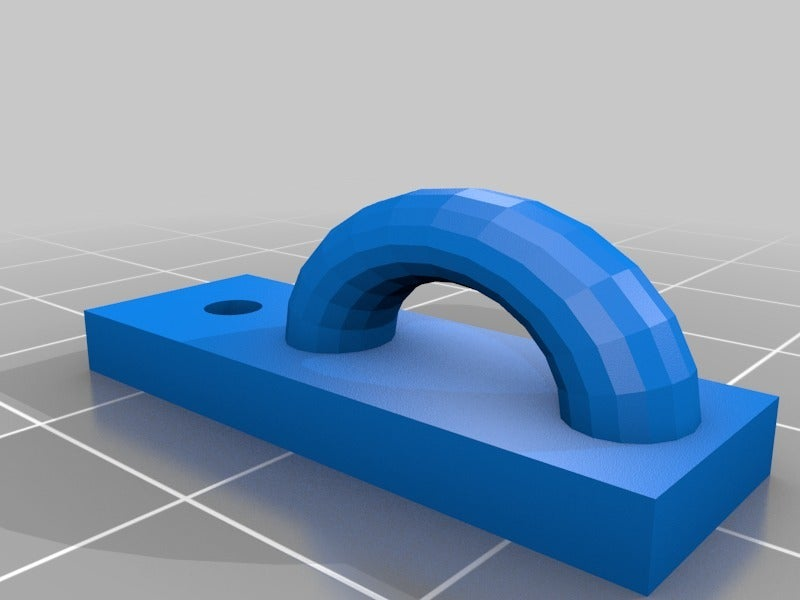
16) The three towers and their associated endstops and motors are X - front left, Y - front right and Z-back. Run the wires up the back of the z tower, using the wire holders which are attached through the linear rails with m3 bolts, ensure the heads are small, and sit fully into the recesses in the linear rail, the carriage must be able to slide over them. Run the power supply wiring down this channel, add some cable protector and cable ties.
17) Attach motors to ramps board, X, Y and Z. Each motor has 4 wires comprised of two pairs. Identify which of the wires are pairs by using a multimeter on resistance/ohms. A pair have some measurable resistance between them. One pair goes to one side of the connector on the ramps board, the other pair goes to the other side. If the motor moves the wrong way when you home the printer later on, TURN THE POWER OFF then turn the connector around 180 degrees. If all the wires from all the motors are bundled together and you need to work out which motor is which connect the multimeter on volts across a pair of wires and spin a motor the one which is connected to the meter will generate a small voltage.
18) Connect the endstops to the X Y and Z MAX endstop connectors. The connectors have 3 pins, positive is towards the middle of the board and is NOT used. As long as the other two connectors go to the NC contacts on the endstop they will work.
18a) Attach a 40mm 12v fan to the top section so that the "open" side of the fan blades faces outwards. Connect the + and - of the fan either to the PSU (could use the ramps power connector as long as you can get a good connection with 2 cables in each connector or use the 12v aux on the ramps board which is next to the x motor driver + is towards the middle of the board. You might consider diverting the spare 12v rail from the x-box PSU that was unused and having a set of screw terminals or something similar for accessories like fans and LED’s.
19) Upload Marlin RCbugfix using arduino IDE software www.arduino.cc . The configuration files (configuration.h and configuration_adv.h) I have provided only work with the version of marlin it was supplied with, in this case RCbugfix dated 23-11-16. If using a different version copy the settings from these config files over to your later version.
20) Homing (any issues with motors making a loud noise or not moving then see 21 below and come back here afterwards). You should be able to attach the usb cable and connect to pronterface using the correct com port (which should auto install on your pc when you connect it to the ramps board) and baud rate 250000. If this doesn't give you a stable connection then change configuration.h baud rate to 128000 and pronterface and try again.
Send M119. The endstops should all show as open. Depress one endstop switch with a finger and send m119 again, that one should change to triggered. Test the other 2. Now do it again but slide your carriages up to ensure they can click the endstop switches and that the correct endstop shows as triggered when they do.
Click "home all" or send g28 but standby to pull the plug from the wall socket if the motors do not all move upwards. If any move down, swap the motor connector on the ramps board around the other way WITH POWER OFF. You change motor direction in firmware but this is messy. When the carriages hit the endstops they should stop and all three will home in turn.
21) Motor current. There are lots of web pages on this available but the crux of it is this - with motor connectors properly attached and the motors powered up i.e. by pressing home/g28, use a screwdriver to touch the little potentiometer (pot) on a motor driver board. Measure the voltage between the pot (screwdriver) and the PSU negative. DO NOT disconnect any motor when powered up, it might kill the driver, and do not touch anything but the pot on the driver board with the screwdriver. Turn the pot to get a voltage of between 0.4v and 0.6v which is a good place to start, every model of motor is different, but as long as the motors move, have reasonable strength, i.e. don’t skip or click if you lightly resist the carriage as it moves, and don't get hot in use then you're there. You want as much current as it takes to get strong movement and holding force but not enough to heat everything up more than is comfortable to touch with your finger i.e. 60 deg C approx.
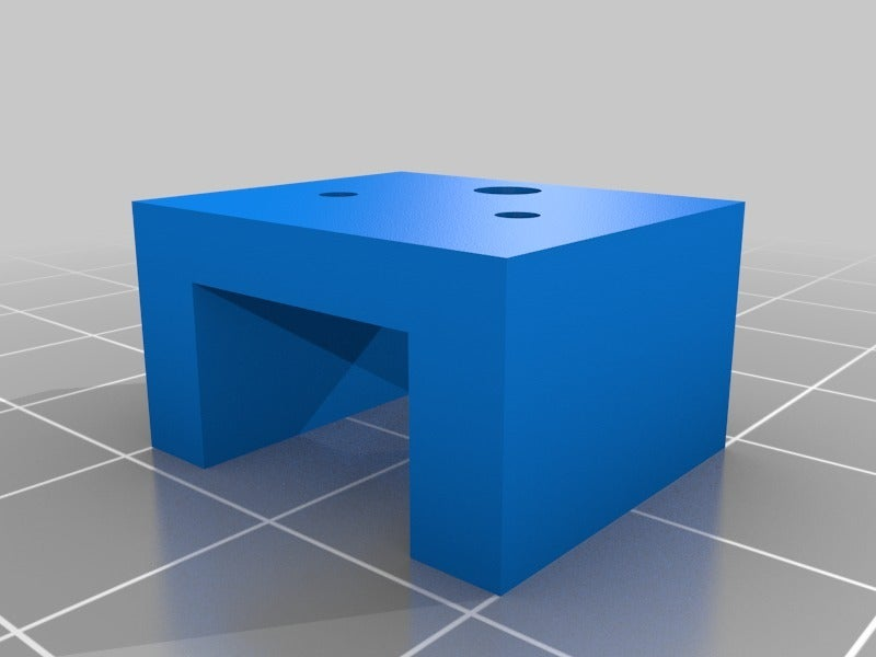
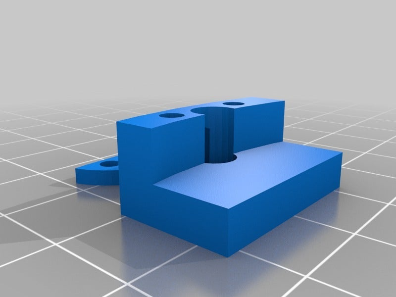
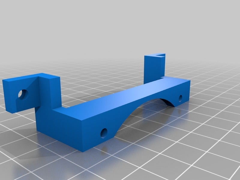
22) Heated bed. I used 3M 300LSE or 468P adhesive double sided tape supplied in A4 sheets. Cut out a piece to match your heated bed to bond the silicone heater pad to the aluminium disc (debur it first with a file if needed), sandwiching a thermistor between the alu disc and heat mat about 1-2cm in from the edge. Use a sheet of cork underneath the heated bed. Attach your print surface to the top with more high temperature adhesive.Cable tie the thermistor to the bed heater wire to ensure it cannot come loose. Run the power cables up the cable management at the back and connect the bed heater wires well (polarity unimportant) to the D8 mosfet output. Do not use solder on the wires as it tends to deform and the connection fails later, but crimps work nicely as does just twisting the stranded wires and doing it up tightly. Connect the thermistor to T1, again polarity unimportant. Print the bed clamps, I have included a standard one, and a narrower one in case your heater mat is square and sticks out a bit. Fix them to the brackets with m3x10 bolts, make sure the heads go down into the recesses and are not high enough to touch the bed, or its insuation, otherwise heat conducts down to the brackets which being PETG will soften when at ABS temperatures. Place the bed into the clamps, there are then 3 small top sections which fix with 2x m3 x10 (or8) bolts to clamp the bed down. Since you have cork (I also put cardboard under the cork) which is compressible a small degree of bed levelling can be achieved by tightening these bolts more or less relative to each other. Aim to level to the lower frame.
23) The firmware is set to use bang-bang i.e. on/off control of the bed heater which works fine in most cases. Set your thermistor type in configuration.h. Make sure it reads close to room temp at room temp. Then try 40 degC, 60 deg C etc.. and see how close you are to the actual temperature best measured using a k-type thermocouple with a blob of heatsink compound around it, pressed to the bed. You might need to try different thermistor tables/types to find the best match, try a range of temperatures for each one you try to include 60 degC and 110 Deg C (PLA/ABS). Please note with PEI or printbite on top, or glass the temperature on the bed surface will be lower than the temperature measured by the thermistor under the aluminium, so dial in a higher temp when printing to get the ideal 65/115 at the bed surface. I am not sure if the PETG lower section will soften when the bed has been hot for a long time, more work might have to be done here to insulate the bed if it does.
24) Calibrate motion using least squares method. You can attach your hot end or a pen (pen holder is part of the stls. If attaching a pen, clamp it tightly, mark the pen so that the amount hanging down below the effector is the same length as your hot end will be.
Now move the effector down to the bed in the centre with the pen just touching the bed. Measure the distance from the carriage top to the endstop switch. This is your approximate max z height. Go into configuration.h and change #define
MANUAL_Z_HOME_POS to this value, make sure (move it if necessary) this line comes before #define
Z_MAX_POS MANUAL_Z_HOME_POS so that the value is defined for the firmware. Add 2mm to it to give you a bit of overhead for calibration, this firmware won’t allow you to go below z=0 which you might have to do calibrate.
Now go to http://escher3d.com/pages/wizards/wizarddelta.php and enter the initial details, endstop corrections are 0, diagonal rod length is the length of your rods from ball joint to ball joint or the distance from centre to centre of the bolts on your rod making jig. Mine is 108mm.
Delta radius you can get from diagrams like this https://goo.gl/images/SQOIXH Im using 59.2
Homed height is your manual z home value.
Printable radius is the max radius your hot end can reach without the nozzle coming off the bed or the effector hitting anything like a belt/tower etc.. It will be 20% less than your bed radius approx. so my 120mm bed has around 100mm (50mm radius) printable. Move the head around and be sure you don’t hit anything at x_max/min and y_max/min
Select calibrate 7 points and 6 factors. Generate points, these are coordinates to probe. It easiest to make custom buttons in pronterface with P0, P1 as the names so you can quickly move to each point.
Move to point 0 with the pen tip above the bed. Lower the effector in small increments until the pen tip grips a piece of paper between it and the bed. Enter the value for z-height, so if the nozzle hits at z=2 then enter -2. Raise the effector 5mm and move to the next point do the same. Probe all the points. Transfer all the values into the boxes in the calculator and hit calculate. It will give you an m665 command with some values, and a m666 command.
M665 L108.00 R59.20 S200.00 A0.00 B0.00 C0.00
So L is diagonal rod length, R is delta radius, S is segments per second, A, B and C are rod corrections which we are not using.
M666 X-2.62 Y0.00 Z-2.13
The are endstop corrections, they essentially level the bed with the effector and carriages. After homing the firmware lowers each carriage by the amount shown. This used to be done with screws on the carriages to change the endstop trigger points, now its software which is easier.
Copy these commands and paste them into pronterface console and send them. When both are sent, send m500 to store them to eeprom, you will get a confirmation “settings stored” so they don't disappear when you power off.
Now update the initial values in the calculator with your new values and do it again. If it suggests tower angle corrections remove them and ensure they are 0. Each time you do this the values will change less until they hardly change at all. At this point you're reasonably well calibrated.
It will suggest a new height value if you want you can enter it in configuration.h and reupload.
Test it by moving sending G1 X0 Y0 Z3 F1000. Now move the effector around using pronterface the pen tip should remain at the same height above the bed as you move around.
Once you have a hot end attached you should do this again, the values won’t change much but the calibration will be more accurate the more you do it and the less the values change.
25) Hot end. Assemble and attach your hot end. Thermistor goes to T0, heater to D10. Fan to permanent 12v, so it’s on all the time. Make sure when you heat it up the heater block reads the same temperature or as close as possible to the temperature you've asked for. Since PID helps with hot ends, run PID tuning http://reprap.org/wiki/PID_Tuning and get nice accurate PID values enter them into configuration.h.
26) Extruder. Leave the bowden tube off the extruder for now. Insert a length of filament approximately 20cm. Tighten the idler so that it grips it tightly but doesn't squash it flat. Now send M302 which will allow cold extrudes so you can test it. Ask pronterface to extrude 10mm at 100 mm/min. Make sure the filament goes the right way, i.e. towards the bowden tube. If not swap the motor connector around WITH POWER OFF. Now mark the filament as it enters the extruder with a sharpie marker, then at 50mm and 70mm above this. Ask for 50mm extrusion and see how far it goes. The amount you got we can call A. Now do this calculation: 50mm/A. The value will be 1.x if too little or 0.x if too much. Now multiply that value by your E steps/mm from configuration.h and change the E steps value and reupload. Try again you should get 50mm of filament when you ask for 50mm of filament.
"#define DEFAULT_AXIS_STEPS_PER_UNIT {100, 100, 100, 465} // default steps per unit for Kossel (GT2, 20 tooth)"
The first 3 values are x, y, z motors - 100 is the steps/mm for the tower motors assuming 16 tooth pulleys, gt2 belts, 1.8deg motors and 1/16th microstepping. If anything you are using differs from these use http://prusaprinters.org/calculator/ the stepper motors section to generate a new value, they must all be the same for delta printers. The fourth value is extruder steps/mm.
It is also worth testing your extruder’s maximum speed here too. Send M302. Then ask for 10mm of extrusion at 100mm/min. This is slow and it should feed nicely. Now try speed 200, then 300 etc keep going until the motor stalls (makes a hum but doesn't turn). Now try increasing the current a bit (see above) and try again. The value you derive is the fastest your extruder can move. Remember this is mm/min so divide by 60 to get mm/s which is what most slicers use. You can use this value (or approx 10% less) in your slicer as your retraction speed, you want as fast as you can, without risking stalling the motor.
26) Bowden tube. Cut ends of bowden tube with a sharp knife at exactly 90 degrees cleanly. Push them into the bowden couplers on the extruder and hot end. Make sure there is no play in the tube, as this will lessen the effectiveness of your retractions which prevent blobs/strings (to some extent) when printing.
27) If your extruder is calibrated, your delta motion calibrated and your hot end and heated bed heat up to the right temperature, then you can try printing something. Getting the gap between nozzle and bed (when everything is hot) is the key to printing well. You can change this by sending M206 commands to change the home offset or by using a z-offset setting in your slicer, or by babystepping which I have enabled by default in configuration_adv.h in the sample firmware. Access this via the tune menu when a print has begun and use the lcd rotary encoder to move the nozzle up and down to get a nice first layer. Record the amount you moved, it will be shown on the display in mm. Use this for the next print as your z-offset. You don't have to do this every time (but to be fair it only takes 2 seconds and you are going to watch the first layer anyway).
There is a nice option in this latest marlin in configuration_adv.h called “smooth moves” this effectively disables the lcd when the processor is under demand to prevent stuttering, a common problem for deltas because of the heavy maths for the slow processor on the Arduino mega. If you enable it you might get better prints but babystepping will be hard to do as accessing the lcd will be tricky. So use it when your machine is well dialled in - if higher speed printing results in stuttering.
Enjoy, and please modify and improve on the machine in any way you wish, let me know if you do and the best mods will be incorporated here on the original.
If you wish to copy/edit the file you can do so here:
Effector, carriages, Pen holder
https://www.tinkercad.com/things/aqAdijdevtg-ddm-effector-carriages/editv2
Main printer base, top
https://www.tinkercad.com/things/aZqTAgyDZLD-demondeltamicro/editv2
Base with improved holes for motors
https://www.tinkercad.com/things/aFzOv26h1fj-ddm-motor-mounts-v02/editv2
:format(webp)/https://fbi.cults3d.com/uploaders/15715760/illustration-file/4f050701-ff06-4f83-b1ea-891f0fd5094b/IMG_20161203_15563601.jpeg)


/https://preview3d-images.cults3d.com/variants/mjm8xs3wdexhxvjqsecxnd8txczd/848ec152657411c3fb217bef17c5a518f412feacc875ce6f22e14239149a46cd)
/https://preview3d-images.cults3d.com/variants/i9g9f1mnr3in620l7wd1z3mjo9j6/848ec152657411c3fb217bef17c5a518f412feacc875ce6f22e14239149a46cd)
/https://preview3d-images.cults3d.com/variants/fe84samu6pyjzlyyjnrvf35w98vg/848ec152657411c3fb217bef17c5a518f412feacc875ce6f22e14239149a46cd)
/https://preview3d-images.cults3d.com/variants/c8093a75u7i3q6oylbk18yk4e50l/848ec152657411c3fb217bef17c5a518f412feacc875ce6f22e14239149a46cd)
/https://preview3d-images.cults3d.com/variants/sll7im5ksvbmf4387g0qle3ym7ed/848ec152657411c3fb217bef17c5a518f412feacc875ce6f22e14239149a46cd)
/https://preview3d-images.cults3d.com/variants/hz5xclwq87rs6yykco9u2p4svtlt/848ec152657411c3fb217bef17c5a518f412feacc875ce6f22e14239149a46cd)
/https://preview3d-images.cults3d.com/variants/jg1gsyhjc25wp8dyzkgs27s30g38/848ec152657411c3fb217bef17c5a518f412feacc875ce6f22e14239149a46cd)
/https://preview3d-images.cults3d.com/variants/whzidcmu3kocjxqhu399zmdub2wn/848ec152657411c3fb217bef17c5a518f412feacc875ce6f22e14239149a46cd)
/https://preview3d-images.cults3d.com/variants/6ceys3ggyvsalqj10oxvafyvn8pt/848ec152657411c3fb217bef17c5a518f412feacc875ce6f22e14239149a46cd)
/https://preview3d-images.cults3d.com/variants/zdtcr5fq41r3tpo9x307l73sorvn/848ec152657411c3fb217bef17c5a518f412feacc875ce6f22e14239149a46cd)
/https://preview3d-images.cults3d.com/variants/uwcs37toqmypd418j5dqfbbcxdpz/848ec152657411c3fb217bef17c5a518f412feacc875ce6f22e14239149a46cd)
/https://preview3d-images.cults3d.com/variants/fok1seonzmd08ic2nqefft7qq9fp/848ec152657411c3fb217bef17c5a518f412feacc875ce6f22e14239149a46cd)
/https://preview3d-images.cults3d.com/variants/izowrgxf2aratu9yyjdtfehpvh07/848ec152657411c3fb217bef17c5a518f412feacc875ce6f22e14239149a46cd)
/https://preview3d-images.cults3d.com/variants/o5lp9d2ecbhwvrregsb4maz3q5bl/848ec152657411c3fb217bef17c5a518f412feacc875ce6f22e14239149a46cd)
/https://preview3d-images.cults3d.com/variants/s526r8rc3xgv99vh27353z40a4im/848ec152657411c3fb217bef17c5a518f412feacc875ce6f22e14239149a46cd)
/https://preview3d-images.cults3d.com/variants/rll8u2o70gdlojtxmdyfvrcxz4o3/848ec152657411c3fb217bef17c5a518f412feacc875ce6f22e14239149a46cd)
/https://preview3d-images.cults3d.com/variants/gw4hp6rzp1zp720cyfxg0o1tbkcw/848ec152657411c3fb217bef17c5a518f412feacc875ce6f22e14239149a46cd)
/https://preview3d-images.cults3d.com/variants/8ltzuk1r44k2t6v20pxn5d4ydj6j/848ec152657411c3fb217bef17c5a518f412feacc875ce6f22e14239149a46cd)


