#Featured on Hackaday!

#The
Pi Project Family!
Super RetroPie Pod (https://www.thingiverse.com/thing:3293876), The Raspberry Pi Desktop Arcade (https://www.thingiverse.com/thing:3279207) And of course Bananananana (https://www.thingiverse.com/make:754382) and The Green Demon (https://www.thingiverse.com/make:623008)
This is mostly based on my Rasptop from https://www.thingiverse.com/thing:2804933
#Build
it already!
It will cost about $150-350 USD to build based on choices of parts and computer inside.
It uses the same palmrest screws, keyboard, speakers, hinge screws, and USB panel mounts as the Rasptop above but with a better screen and more versatility.
#A note on screen choices!
The Official Raspberry Pi Foundation Touchscreen has a resolution of 800x480 and is the easiest to wire but it's expensive to buy and that resolution is TERRIBLE for day to day use. You can force it to a better resolution on a Raspberry Pi by using the config.txt and setting the framebuffer size higher.
Set as follows:
framebuffer_width=1024
framebuffer_height=614
That helps a lot, but it's a hack.
There's many HDMI screens of better resolution out there and that's why I made the 2.0 here. I used a 1024x800 HDMI 7" 10 point touchscreen listed in the BOM. These are commonly USB powered and use USB for the touchscreen too. Both windows and linu supports it out of the box. Super easy!
Now, I have found that I needed to tweak the config.txt for these HDMI screen to boot properly too. Here's what I added:
hdmi_force_hotplug=1
disable_overscan=1
hdmi_group=2
hdmi_mode=87
You can put that at the bottom of your config.txt and this will set the HDMI mode to run these small screens.
There's also 800x600 versions of the same screen. While better than the RPi one it's still not much screen space and can it can be tough to fit things on the screen.
Just be aware of what you're buying! It's easy to go down a path that might lead to future frustration! I am super willing to help anyone build this though, PM me if you need a hand!
One more thing, If you get the voltage warning symbol you can disable it with this line in the config.txt
avoid_warnings=1
Also, I like to have the lights on my Pi setup so the red light is only on when the machine is off, like if you tell it to shutdown the red light comes on when it's safe to power down:
dtparam=pwr_led_trigger=none
dtparam=pwr_led_activelow=off
And finally I like the green light to pulse based on system load. This is called heartbeat:
dtparam=act_led_trigger=heartbeat
#Off
the shelf parts!
I made some big changes that well, made it thicker and larger but this allows it to be made with straight up off the shelf parts.
#You
will be soldering, wiring and setting up Linux!
Be aware of what you're getting into! Also I made the source files in SolidWorks 2017. Hit me up if you would like them sent to you in some other format, I will see what I can do.
#BOM
#Raspberry
Pi 4B fits!
#Notes
on chargers:
With the 2 cell system, which is the best way to run this, you have some options for charging. If you plan to use this a lot especially while on charge I suggest a 5 amp charger board while a 2 amp is fine for most uses. I got mine most recently at Banggood. They offer the 2S 5 amp ones pretty cheap and they work good.
Either way you should add a heatsink to the charger board.
I got an assortment of small heatsinks and some thermal glue from amazon pretty cheap. On the 5 amp boards I used 2 heatsinks, one on top of the chip and one under it. For the 2 amp board I just used one heatsink on top of the chip. The thermal glue is not conductive so I used quite a bit on the top heatsinks to help them stay stable over the chip.

This is the 5 amp board without and with heatsinks.
#If
links are dead:
Let me know or search the item. The battery one keeps changing. You want a 10,000MAH booster pack with a LiPo battery. These are often sold as slim type about $10 USD.
#Up
Board option, Intel Atom and Full X64 System
Up Board This is a Intel processor x86[64bit] capable PC in a Raspberry Pi 3 form factor. I have uploaded a special base to support this board. You should also purchase the Active Cooling the USB 3 OTG cable and the USB 2 Dual Port Cable since it does not include onboard WIFi or Bluetooth I am using a Mini USB WiFI/BT
The base for the Up board is 33mm deep. The extra depth is for the cooling. There's a lot going on for this little board but hey, it plays Crysis!!
#Power
Options!
#7.4v 2S LiPo high output and long runtime:
Use this one please. It provides the best results and the longest battery life. Used with a 9 volt charger it charges up quickly and safely with little excess heat.

#How
I wired it:
Starting with the batteries I wired them each with a length of 20ga silicone wire then on the balance board you connect positive from one cell and negative from the other to the B+ and B+ tabs on the balance board. The leftover positve and negative wire both go to the BM pad together making a series connection.
The P+ and P- from the balance board then go to the MOSFET input side. This is also where the positive and negative from the charger board attach so it can charge with the switch off. I used 24GA wire from the charger to the cells. I also used 24gs from the DC barrel jack to the charger board.
You need a wire from Battery + to go to the switch as well, this can be 24ga or even smaller. and the wire coming back from the switch goes to the input signal on the MOSFET module.
On the output of the MOSFET module connect the battery level indicator and the DC to DC converter board so they come on when the switch is on.
#Be
sure to set the voltage before connecting anything to the DC to DC converter!
#No
more than 5.2 volts. Set to 5.1 volts!
I put the Micro USB in still and just wired it directly to the 5v side of the system so I can plug power in there and not use the battery to run it on the bench or something.
So in a test with Ubuntu 18.04 MATE and Chromium browser running Google Play Music I got 14.5 hours of battery life on a full charge playing over bluetooth speakers and doing other random things on this battery arrangement.
#14.5 hours!?
Yeah, a lot of battery.
#Adafruit
Powerboost:
This is the worst option but easier to wire. It provides a MAX of 2 amps! So be aware a Pi 3b+ is pushing it. This is not recommended.
#Only
RPI3 form factor fits as is!
I am using the Asus Tinkerboard inside mine:
https://www.asus.com/us/Single-Board-Computer/Tinker-Board/
Powerful board that fits where an RPi3 fits!
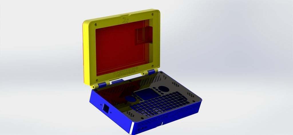
Inside this the screen bezel is changed to hold the new LCD unit and the Pi has been moved to the left to make room for HDMI wiring. Due to space constraints I am removing the HDMI port from the screen to replace it with a 20 pin .5mm pitch FFC connector. This will connect to the cable listed above to carry the HDMI signal to the screen.
The screen is powered by a micro USB port, this is also how the touchscreen connects to the PC. To make this work I used the Hackable USB hub listed in BOM to carry the USB signal for the screen as well as connect to the keyboard USB port. This leaves 2 internal ports left if I wish.
The audio plugs into the headphone jack, the HDMI plugs into the HDMI port. The batteries sit to the right inside the case, electronics to the left.
The little spacers are for holding the screen PCB in. Need 4 of them and they go between the screen PCB and Bezel Rear Cover so the screws hold it all tight. The screws are for m3x14mm.
For the keyboard I hooked it to the 5v lines and used a 3.3v 500mah regulator attached to the battery input. This is enough that it wont show a low battery light on the keyboard.
What also works to power the keyboard is hooking the battery lines of the keyboard to the GND and 3.3V pins on the computer. It draws less than 50ma so this is perfectly acceptable.
The unit size is still 200x150mm approx! Should fit on any 220x220 printer like the Anet A8 I have.
I recommend PLA for this one! With the hinge and way it's setup PLA has the best properties. See Print Settings for details.
Again once done there will be lots of pictures and more detailed instructions. For now Like, Comment and Share!
If you have an idea or feature let me know.
UPDATE 4/13/2018 Updated files for Adafruit Powerboost 1000 use. All parts have been ordered. Screens are coming from China but I hope to have them in 2 weeks.
Update 4/14/18 First part is printed! The base: https://youtu.be/FfbuAbDIj-k
Update 4/15/18 Printed the base and made some adjustments to fit things in better. Debating making the whole thing a little deeper to fit more ports but... I think not, I dunno.
Update 4/16/18 Updated the base to make it even easier to print and stronger with still better air flow. Removed side vents and added 3rd row to front vents. Cleaned up the files and re-rendered in colors.
Update 4/27/2018 Got all the parts! Now the design should be close to final. Printing it now!
Update 5/5/18 Been so busy! Anyways I completely rebuilt my printer again after wearing it out. New Bl Touch sensor and glass build surface. Redesigned the screen bezel on this a bit to fit better, but it's a little more of a pain to print now. Also had to rebuild the rear bezel cover for more space. Changed all the slots to hex holes because I like that look. Overall this should look and be quite rugged. All files are re-uploaded.
Update 5/16/18 Been slow going but I finally printed the screen portion and did test fits. It's a little tight side to side so opened that up and now it sits in there much nicer. Due to the way these screens are built the top wound up 2mm thicker.
Update 8/8/18 OK, it's been a minute. I have been testing, printing and working on the power system. I think it's time to step it up to a 2s 8.4 system. This will provide more amps and faster charging, though sacrifices the ability to charge from USB. Still, I think it will be worth it.
I ordered some parts from China on Ebay:
Voltage reg: https://www.ebay.com/itm/5A-Mini-DC-DC-Buck-Step-Down-Converter-Voltage-Regulator-3-3V-5V-6V-9V-12V-24V/263198737343?ssPageName=STRK%3AMEBIDX%3AIT&_trksid=p2060353.m2749.l2649
2 amp charger circuit: https://www.ebay.com/itm/Charging-Charger-Module-1S-3-7V-2S-7-4V-Lithium-Li-ion-18650-Battery-Cell-8-4V/192266131232?ssPageName=STRK%3AMEBIDX%3AIT&_trksid=p2060353.m2749.l2649
USB 2s charger to see how it works: https://www.ebay.com/itm/USB-2S-7-4V-8-4V-Lithium-Lipo-Li-ion-18650-Battery-Charging-Board-Charger-Module/272750949115?ssPageName=STRK%3AMEBIDX%3AIT&_trksid=p2060353.m2749.l2649
And battery protection board: https://www.ebay.com/itm/2S-8A-Li-ion-Lithium-LiPo-Battery-18650-Charger-Protection-Board-Cell-7-4V-8-4V/323268969256?ssPageName=STRK%3AMEBIDX%3AIT&_trksid=p2060353.m2749.l2649
I do plan on using 10k MAH LI-POs. I don't want it to blow up....
#It
didn't blow up!
I finally put it together, check the makes to see it!
- 1/25/19 All files updated! Redesigned the HDMI screen bezel to use a FPV HDMI extension and one of the Raspberry Pi HDMI backpack connectors. This will double the cable back into the space made in the cover.
#It's thick!
By design the whole thing is pretty thick. Not much I can do about this really. Using off the shelf parts means compromises must be made but now besides some weird cobbled together connectors nothing needs to be modded. For the USB I got solder on micro ends and just am using one without the case to fit.
1/26/19 Re created all files and renders. Tweaked the fit and finish for greater ease of use with various design options. Soilidworks 2017 source file included. Unit will need to be printed with support on the base, bezel and back cover. Only the palmrest can be printed with out support and I recommend a .2mm nozzle for that but I did print it with a .4 and a .3mm ok.
2/5/19 Added a pin and socket in the center of the palmrest to help hold it down and support it when typing.
2/22/19 Added the screen bezel and option to use a Raspberry Pi Foundation 7" Touchscreen at 800x480
2/24/19 Added a version of the base with a 8.2mm cutout to fit the DC barrel jack for the 12v charging input on the 7.2v 2S system. This moved the Micro USB down 2 mm. I also added the custom base for the Up Board. This has no SD slot and no micro USB power input. It adds more cooling openings and a USB 3 socket. Mount the USB 3 OTG cable with 3M VHB tabe. This is only for the 2s 7.2v power system.
3/8/19 Up board version built and final files uploaded. For the USB 3.0 port I am using 3M VHB tape that is 2mm thick and the port spacing matches that.
3/22/19 Added a version of the palmrest that uses the listed LiPO battery meter and has a cutout in it to fit.
7/11/19 Added a base modded to hold a RPI 4B with two USB 3 panel mounts in the side. This comes with 7.2v provisions.
12/2/19 Updated the RPI 4B edition adding 2mm to the height and increasing vents to help cool it!
1/16/2020 A year later! (Almost, March 9th, 2019 is the build date) Here's a few pics of the Up! board one. This being a full on Windows 10 X64 machine gets the most use. I have broken the HDMI cable, I dropped it and snapped the hinge off the bezel so it has a copper color one now and the keyboard just got a bit weird so printing a new black palmrest without holes melted in it that are no longer used. The batteries and charging system have worked flawlessly. So has the Up! board. So much power in such a small space!

Still a mess inside!

The Little Green Demon (https://www.thingiverse.com/make:623008)


Up! Boot

Window 10 ready!

New palm rest installed.

Glamor shot on the big CNC knee mill.

Backside with the 4G LTE backpack installed. This attaches with magnets to the laptop and provides cellular internet. This also attaches to my Panasonic Toughbook CF-19 MK7

And Rasptop 2.0 in the wild again. the 7 inch 1024x800 screen is great for on the go media.
- Update 7/29/2020 Added a new bezel and back cover for LCDs with the HDMI port right up near the top and 2 micro USB ports. These seem to be common on Amazon right now. Use the High Wire parts for these.
:format(webp)/https://fbi.cults3d.com/uploaders/16051940/illustration-file/1df38598-9880-4160-8c68-da85970063d5/photo_2020-01-22_12-28-23.jpg)


/https://preview3d-images.cults3d.com/variants/j26hgbu7uxq033gii5sliscnqmvy/2c25dfac9c0c4b3fee1a07527bd1c6bb2fb599b319b4e1ae3ef1d256f7781447)
/https://preview3d-images.cults3d.com/variants/ap955jaxbcucpei4r3xrzccdb1jh/2c25dfac9c0c4b3fee1a07527bd1c6bb2fb599b319b4e1ae3ef1d256f7781447)
/https://preview3d-images.cults3d.com/variants/f15ou9i93vv5i2kmjvptt7z492nq/2c25dfac9c0c4b3fee1a07527bd1c6bb2fb599b319b4e1ae3ef1d256f7781447)
/https://preview3d-images.cults3d.com/variants/abde9vb8k2qi7wake6kdf162yu65/2c25dfac9c0c4b3fee1a07527bd1c6bb2fb599b319b4e1ae3ef1d256f7781447)
/https://preview3d-images.cults3d.com/kb715hpzm2qe9gb7o3p59i2yn7am)
/https://preview3d-images.cults3d.com/variants/j4tfjexyrxd6b2heyjxzsdrqnhhm/2c25dfac9c0c4b3fee1a07527bd1c6bb2fb599b319b4e1ae3ef1d256f7781447)
/https://preview3d-images.cults3d.com/variants/raa3k2648kkuhoizpsd1g3nufuj6/2c25dfac9c0c4b3fee1a07527bd1c6bb2fb599b319b4e1ae3ef1d256f7781447)
/https://preview3d-images.cults3d.com/variants/rxs4rjrvt9wqsm8s0d3zxp0nv8tj/2c25dfac9c0c4b3fee1a07527bd1c6bb2fb599b319b4e1ae3ef1d256f7781447)
/https://preview3d-images.cults3d.com/variants/3disbe11ikqpjwful1tpv7mthfrb/2c25dfac9c0c4b3fee1a07527bd1c6bb2fb599b319b4e1ae3ef1d256f7781447)
/https://preview3d-images.cults3d.com/variants/ch9lo308q7h4toccyf5kkkt01w5f/2c25dfac9c0c4b3fee1a07527bd1c6bb2fb599b319b4e1ae3ef1d256f7781447)
/https://preview3d-images.cults3d.com/variants/wkqtitaaq6ug1e5wlp0z80hdkv6d/2c25dfac9c0c4b3fee1a07527bd1c6bb2fb599b319b4e1ae3ef1d256f7781447)
/https://preview3d-images.cults3d.com/variants/r88nb5fem9npbxurntyhv29nifub/2c25dfac9c0c4b3fee1a07527bd1c6bb2fb599b319b4e1ae3ef1d256f7781447)
/https://preview3d-images.cults3d.com/variants/exrbsmzc5ce1qbh88g5pc8jhk6qy/2c25dfac9c0c4b3fee1a07527bd1c6bb2fb599b319b4e1ae3ef1d256f7781447)


