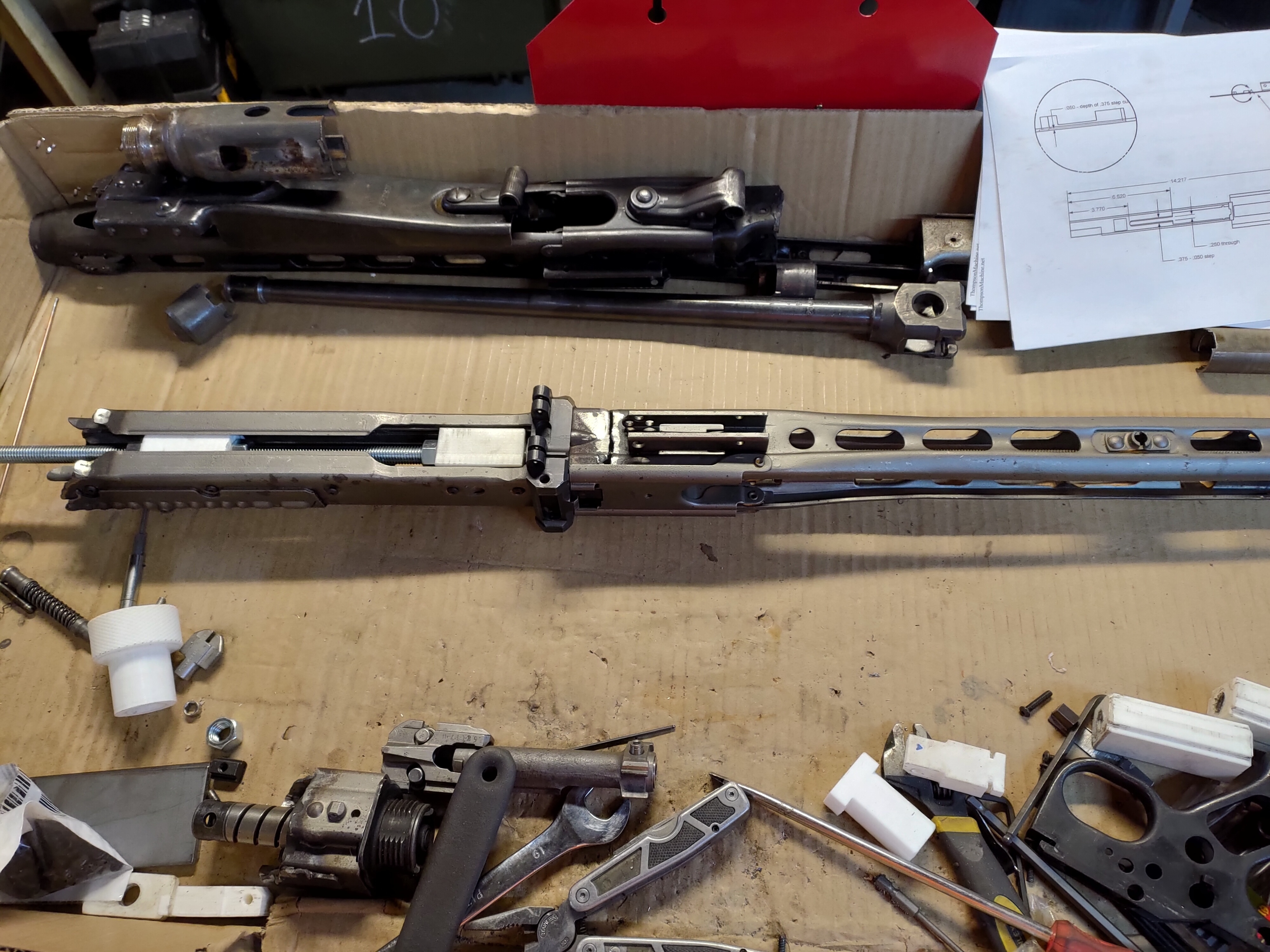
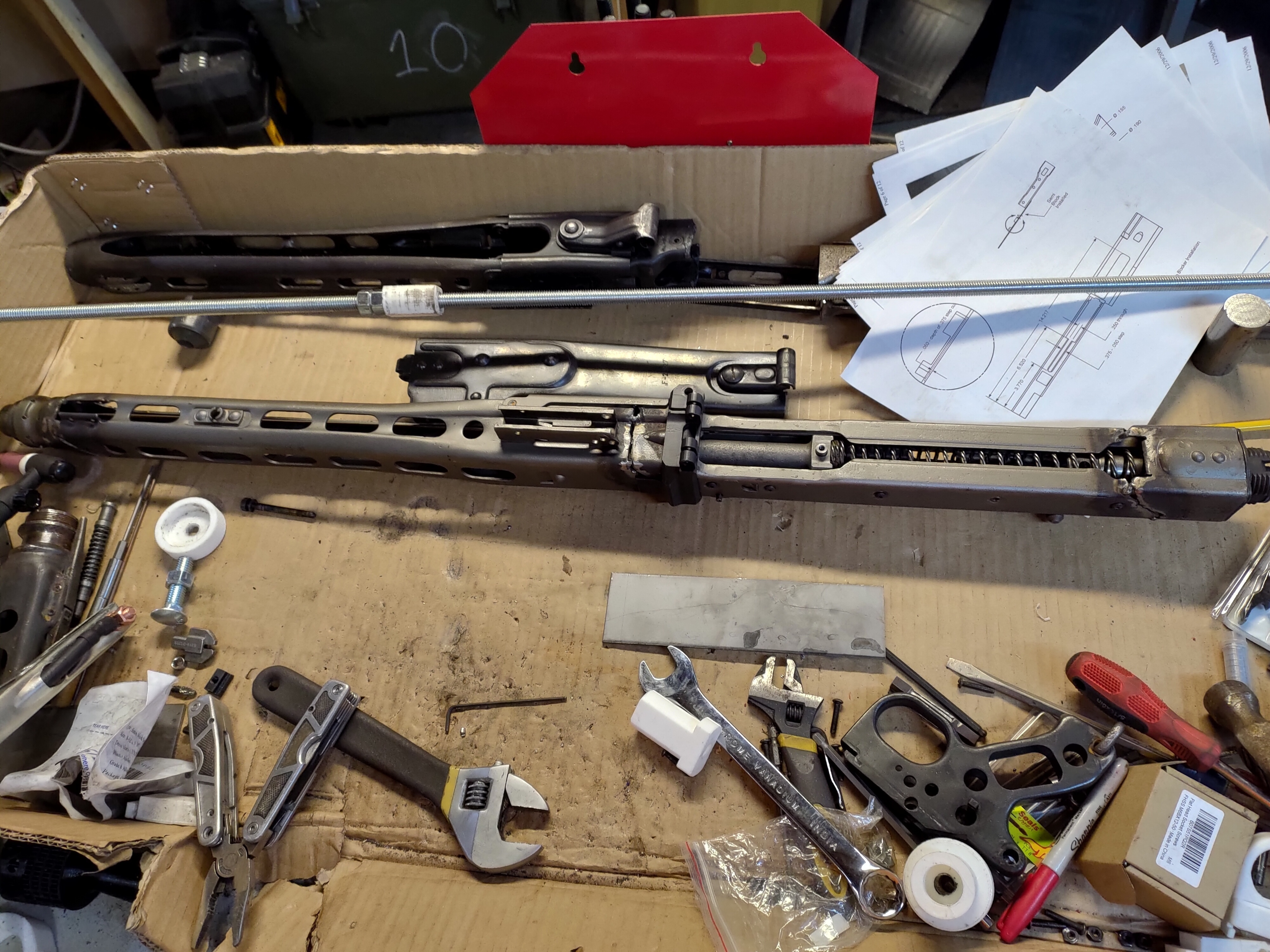
The jig can be used to reweld most mg42, mg3, or m53 receivers. A demilled receiver can easily be rewelded into an in spec receiver in a few hours. There are several kinds of demilled receivers and they each have their own set of challenges when rewelding. 80% receiver halves can also be used, but will require more work.
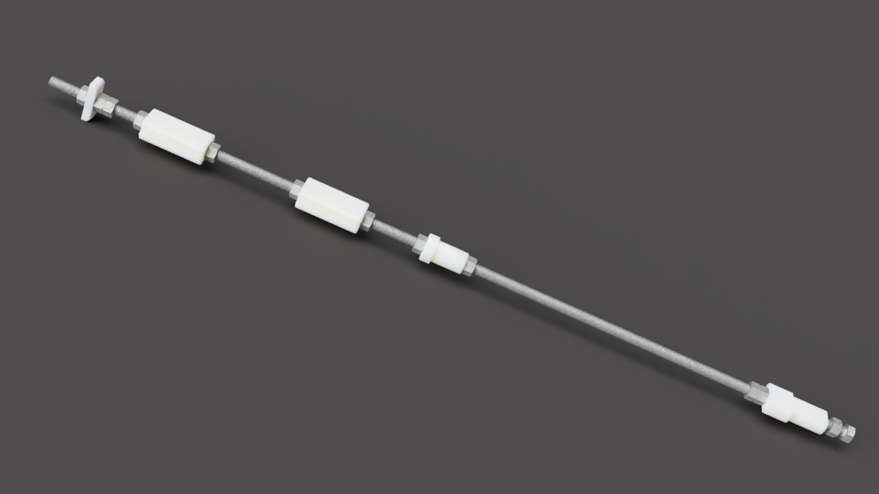
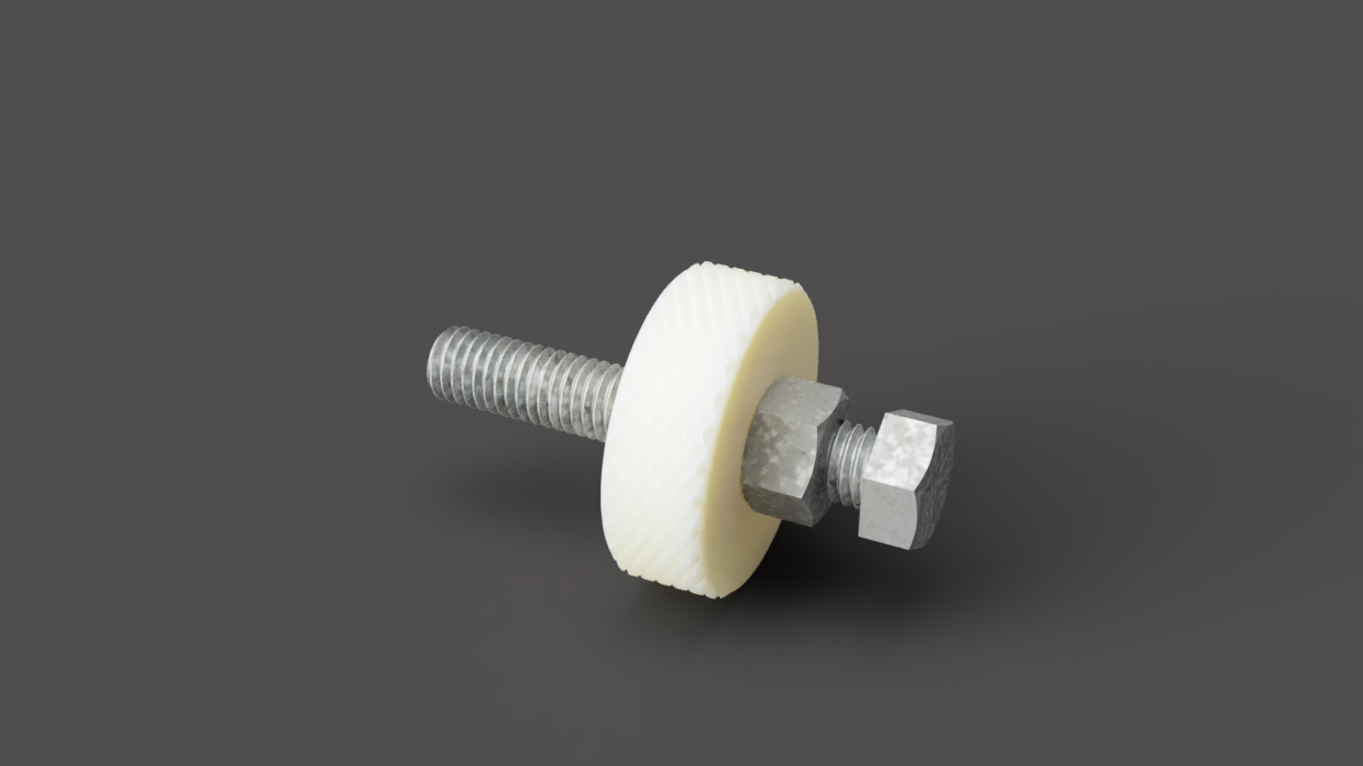
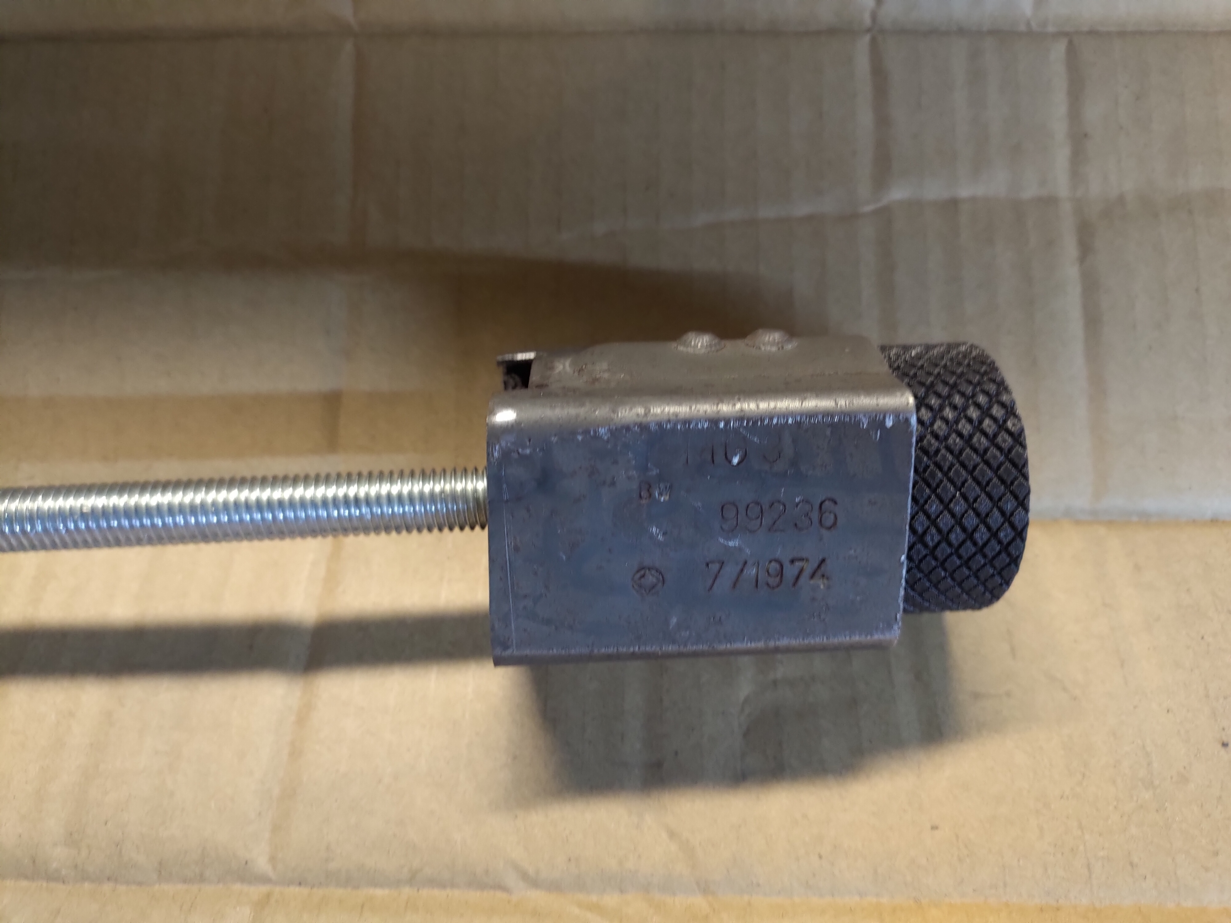
A 3' piece of 1/2"13 threaded, 1 3" bolt and 12 nuts are needed for the jig. I would also recommend using a 2' threaded rod for assembling the smaller sections for welding. The smaller threaded rod can also be screwed into the bushing guide to help push the jig out. 10 8-32 button head cap screws 1/2" long and 10 nuts will be needed for the rails.
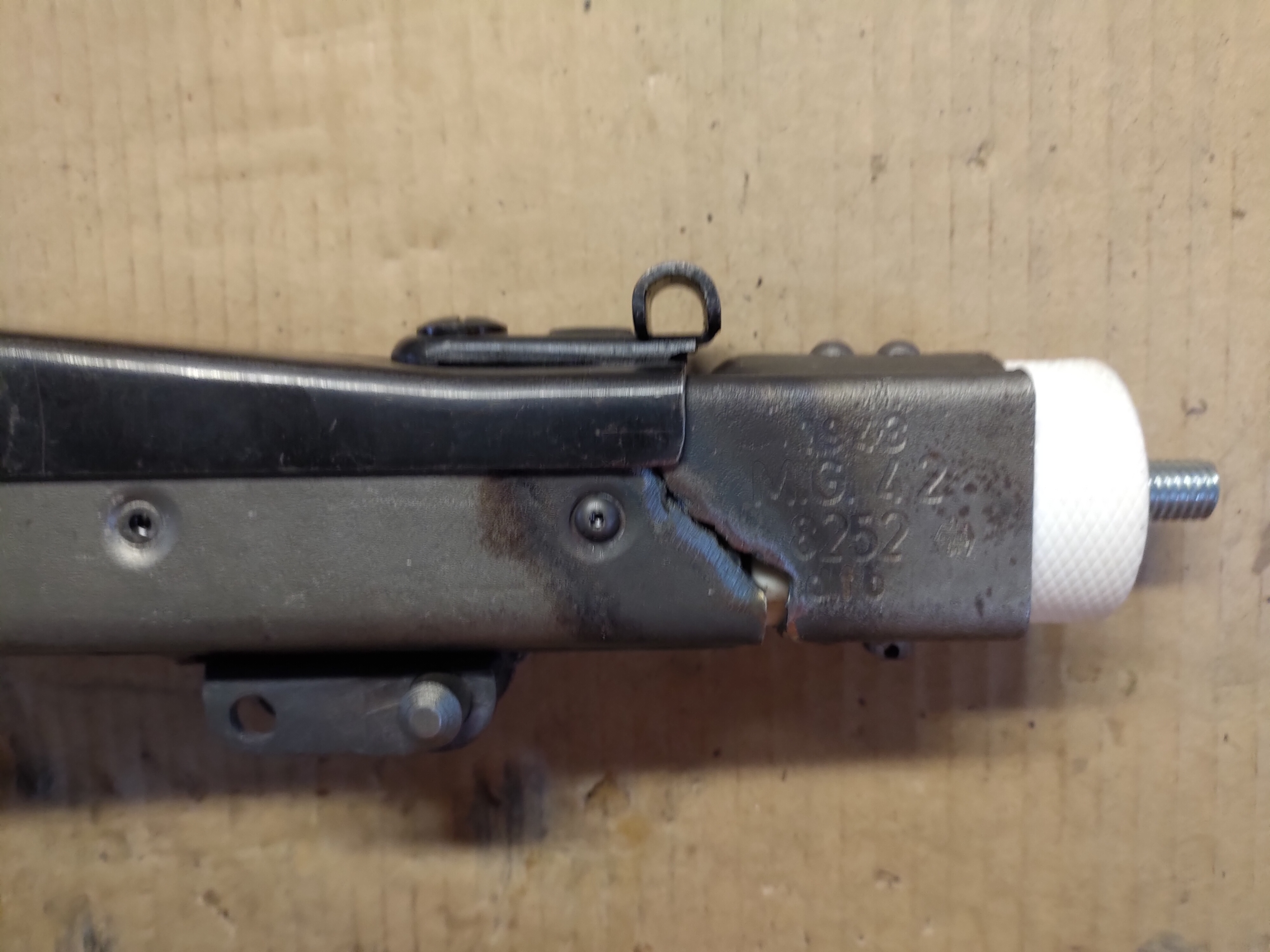
It is best to assemble in sections. First it the shroud, then the action portion of the receiver, and finally the buffer. A full auto bolt blocker must be welded in before any assembly of the action portion of the receiver.
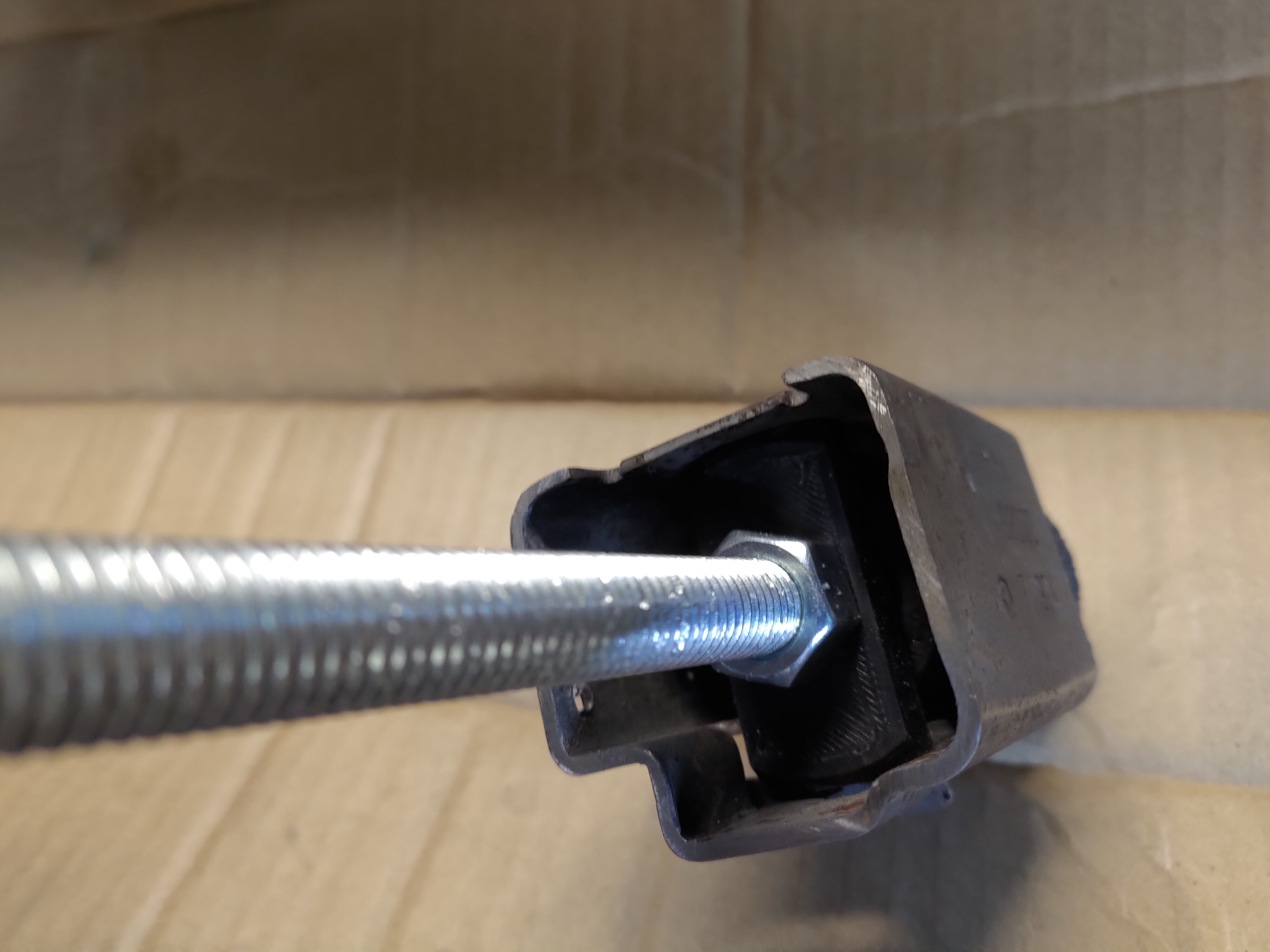
To start screw the barrel_guide onto the threaded rod until it the front of it is 16" from the front end of the threaded rod. Screw a nut onto each end and tighten down.
Next screw on 2 nuts from the front and the bushing_guide. The front of the ring of the bushing_guide needs to be 17-7/8" from the front of the ring of the barrel_guide. Tighten down the two nuts to the bushing_guide. Check the measurement again. If it moved lossen the nuts and adjust until it is exactly 17-78". Insert the jig through the shroud from the back and going through the barrel door. The barrel door will need to be opened part way for the jig to go through. When the barrel_guide is tight up against the barrel stop shut the barrel door and put a clamp on the door.
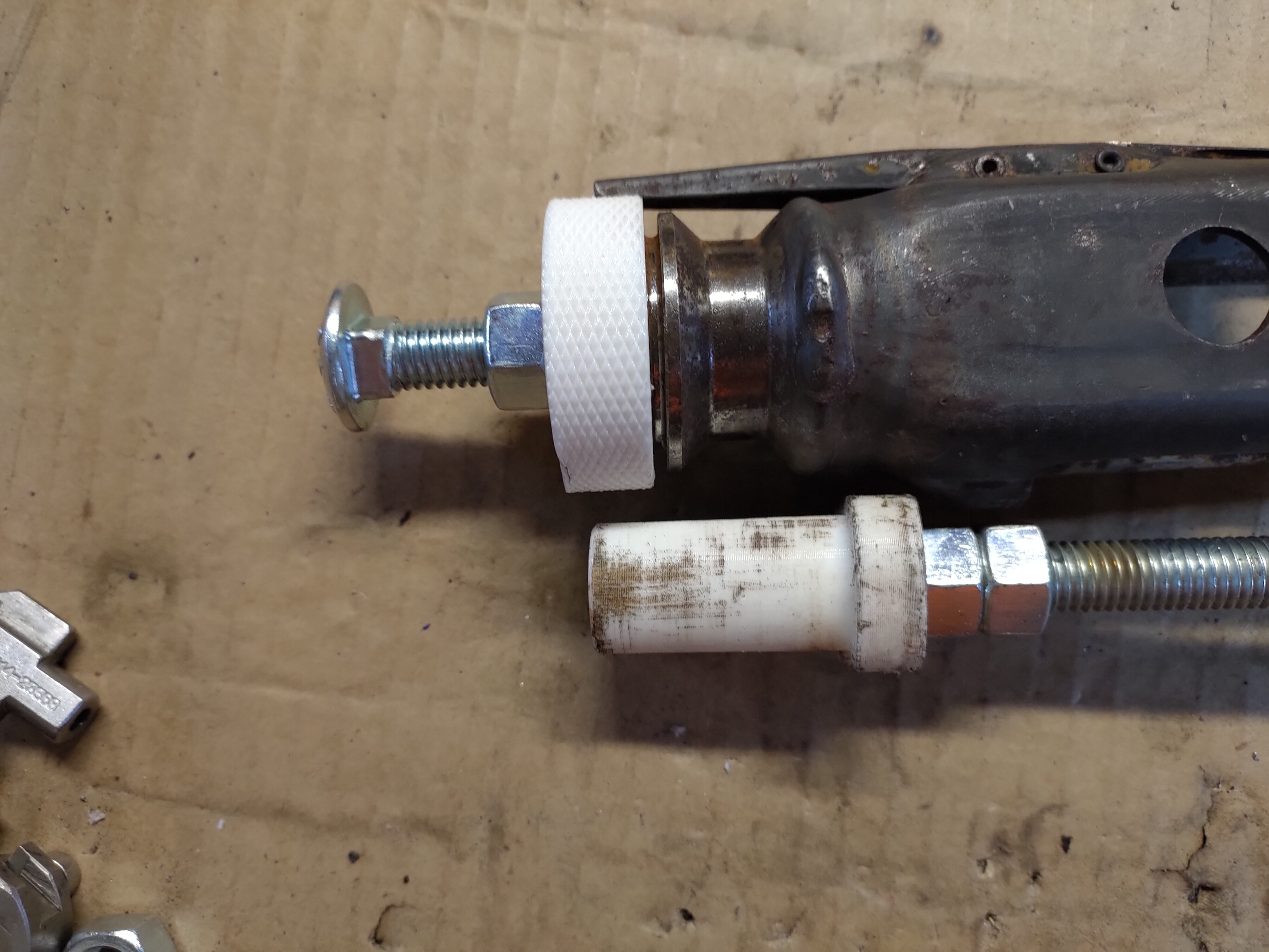
Screw the bushing_nut onto the front receiver bushing. Take the 3" bolt and screw a nut all the way on. The front receiver bushing can now be installed on the jig. Push it on until it is tight against the bushing_guide. Then the 3" bolt can be installed through the bushing_nut into the bushing_guide until it hits the threaded rod. If a new front receiver bushing is used just tighten down the 1/2"nut to the bushing_nut. If it is a cut shroud clamp the side of the bushing section to the shroud so the sheet metal is aligned. Then tighten the 1/2" nut to the bushing_nut.
The bushing can now be tacked to the shroud. Tack it on 4 sides. Try to avoid tacking right next to the bushing_guide if possible.
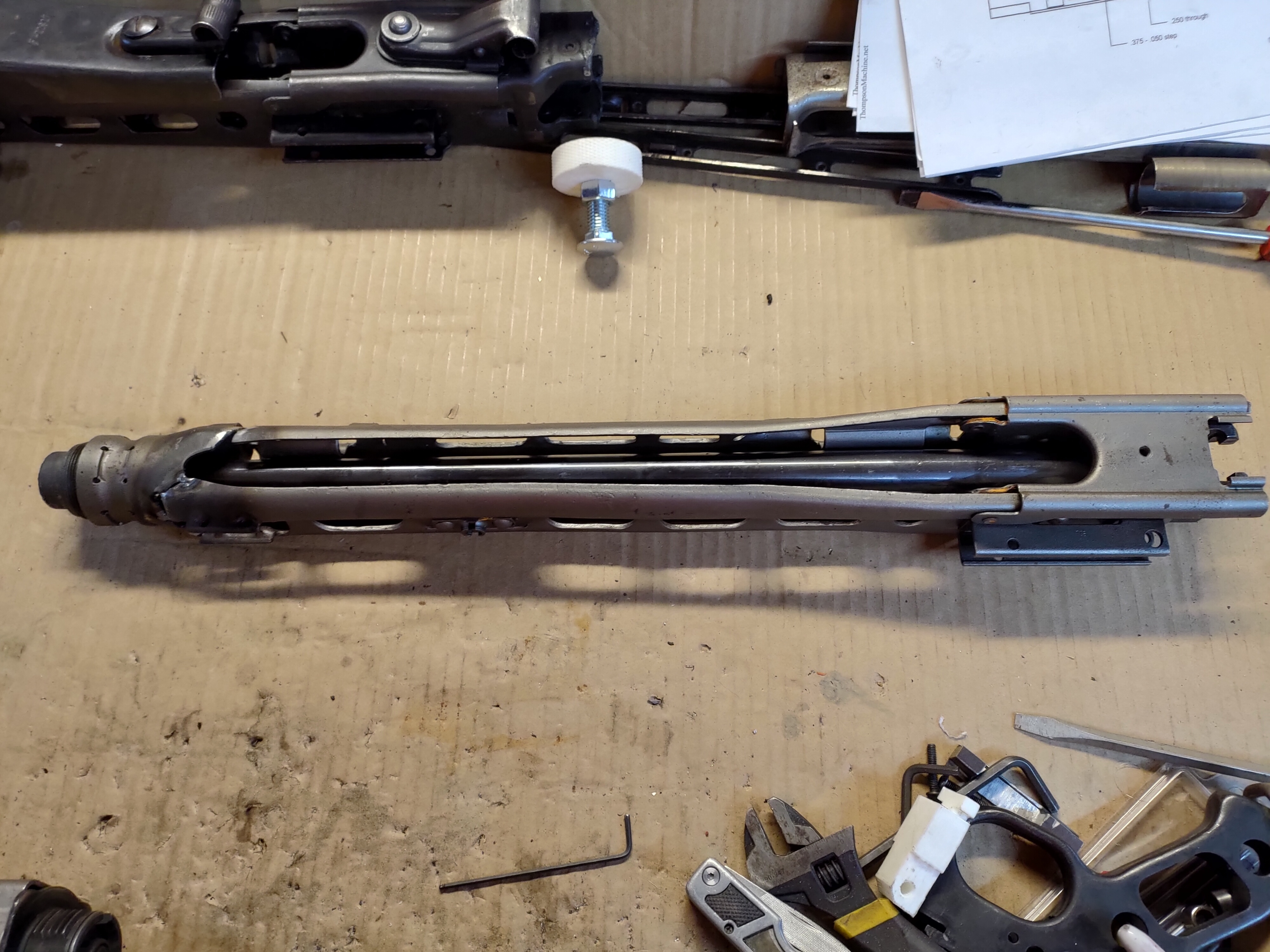
Then remove the jig from the shroud. Install the cam onto the shroud. Install the barrel bushing into the front receiver bushing. Insert the barrel into the shroud and close the barrel door. Push on the front and back of the barrel. It should easily slide back and forth. If it dose not cut the tacks and try again. Make sure the barrel moves easily before going any farther or it will cause major problems later on.
Once the shroud is assembled and the barrel sides easily remove the barrel bushing. The bushing_guide will not be able to be pulled through once the action portion of the receiver is tacked to the shroud. Remove the bushing_ guide from the jig and replace it with bushing_guide_v2. This version will be able to go through the receiver once tacked together. It will not hold the spacing of the front receiver bushing.
Next is the action portion of the receiver. For a reweld it is recommended to use uncut rails. Trying to reweld cut rails will likely result in problems during firing. Install the rails with 8-32 button head cap screws. Install the screws with the heads on the inside of the receiver.
If the action portion of the receiver is cut in multiple pieces it is recommended to assemble the entire section before trying to assemble onto the shroud. Install 2 of the rail_guides onto the threaded rod with a nut on each side. Space the rail_ guides so that they will not be next to any cut that will be welded. Clamp the rail_guides down to a flat surface and tighten the nuts on each side. Then install the receive sections onto the jig. Make sure the sheet metal lines up then tack together.
For rewelding a receiver that was cut through the cam section, install the cam and push the action portion of the receiver tight up to the cam. Rotate until the sheet metal looks lined up then tack together.
For using 80% receiver halves slide them onto the jig and align the sheet metal with the shroud. Use the BRP blueprints so set the spacing off of the shroud then tack together.
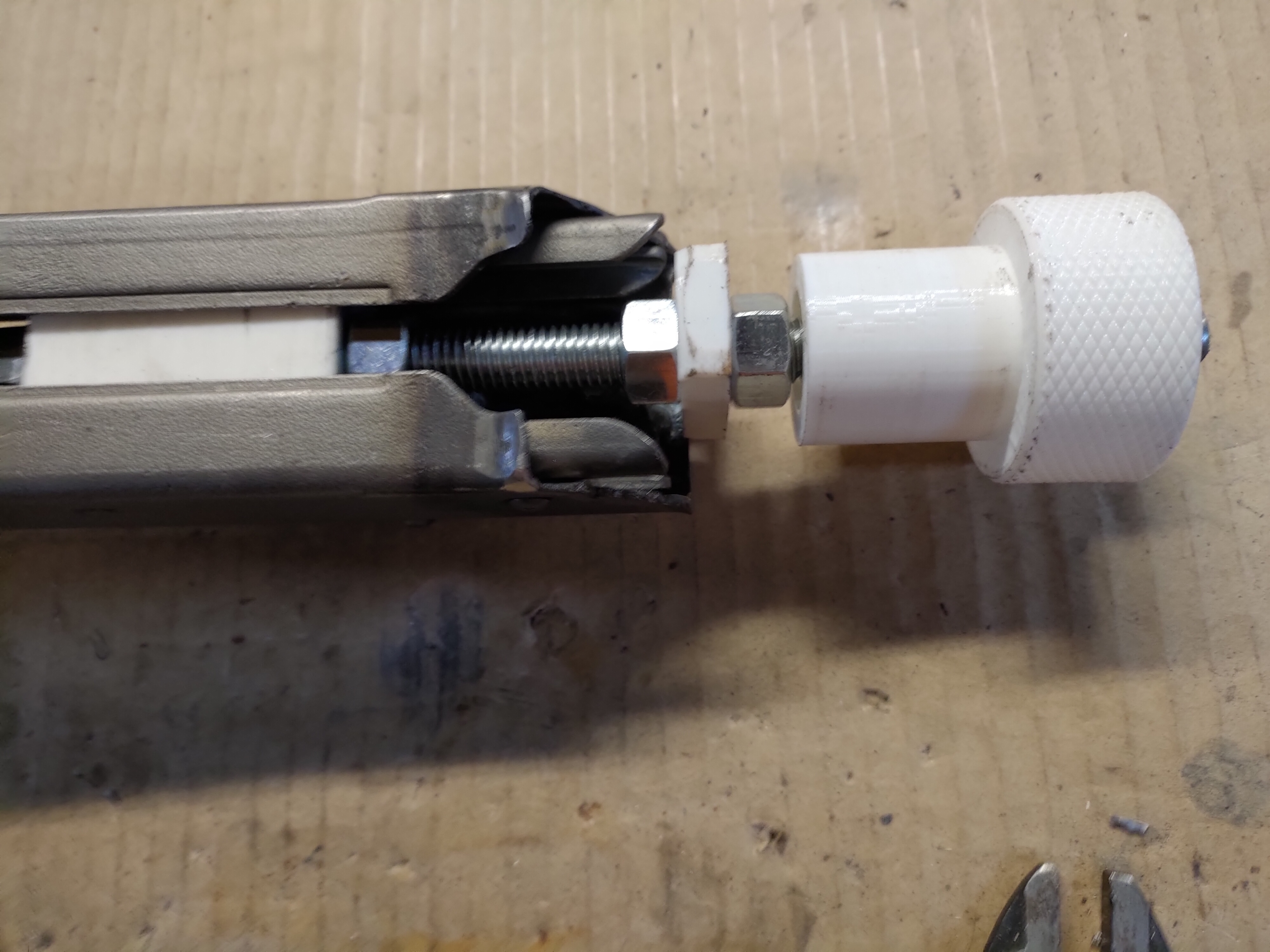
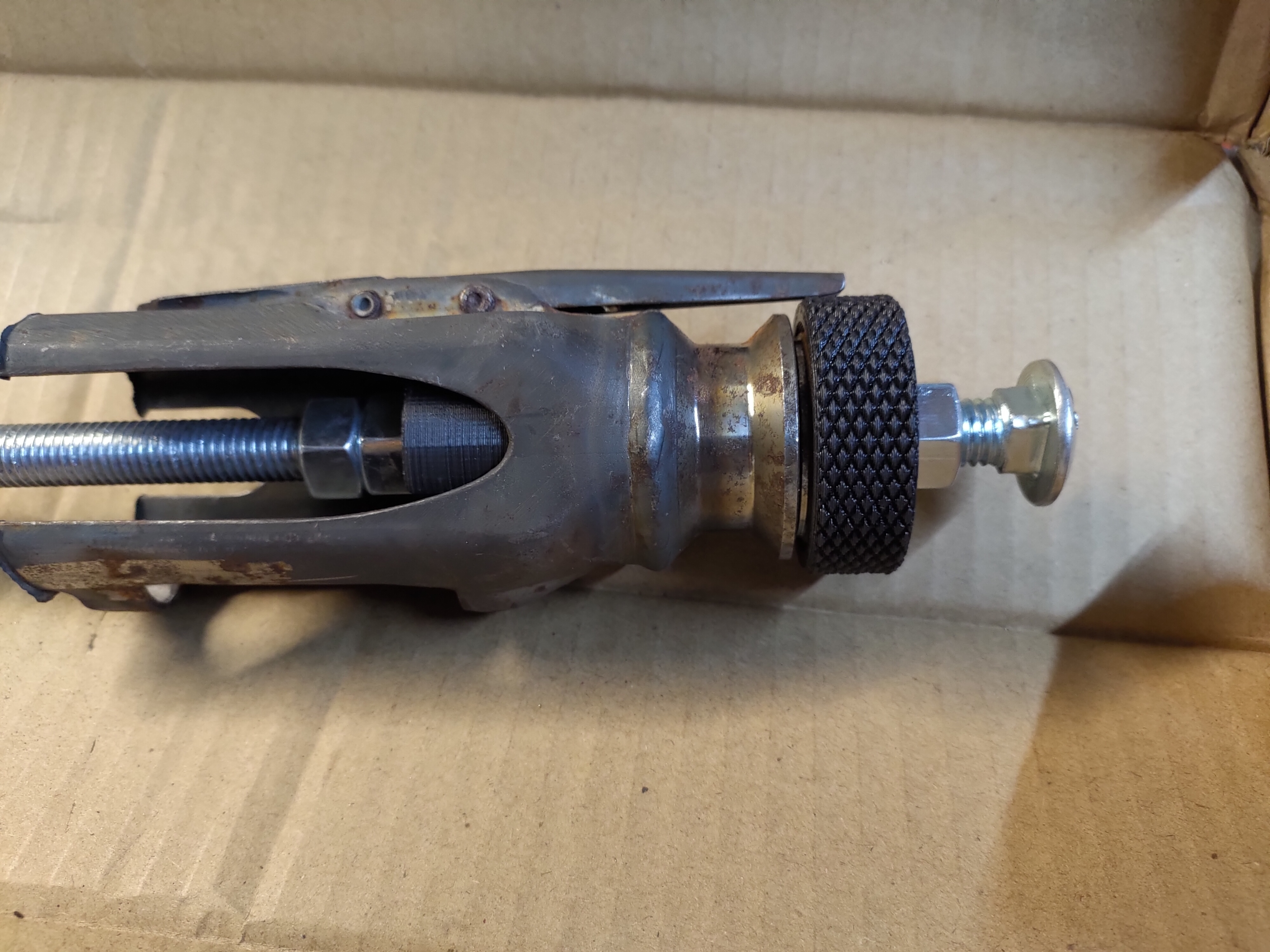
Next is the buffer section. Install one nut, the buffer_stop, then 2 nuts onto the jig. Set the back of the buffer_stop 16-11/16" from the front of the ring of the barrel_guide. Tighten the front to nuts and finger tight the rear nut. Check the measurement again and adjust if needed. Slightly loosen the rear nut. Insert the jig into the receiver. Install the buffer section onto the jig. Rotate the buffer stop so it is vertical with the receiver. Tighten the rear nut. Screw the buffer_nut onto the jig until it is tight with the rear of the buffer section. Install the top cover and verify that it will shut. Rotate the buffer section until it is lined up with the rest of the receiver then tack together.
Now that the receiver is tacked together remove the jig and install the barrel bushing, cam, and
recuperator. Install the barrel then place the front of the barrel on the ground. Push down on the receiver. The barrel should move easily and the recuperator should push it back. Install the bolt and push on the barrel again. The barrel should push the bolt back until it is unlocked. Install the feed tray, top cover, charging handle, recoil spring, and buffer. Cycle the action to make sure nothing is binding. Then install a belt with some snap caps. Cycle the action again and make sure everything moves smoothly.
If everything worked without binding it is time to weld. I recommend doing 1 weld at a time. It is easier to detect problems and avoids more cutting if something did go out of alignment. Install the jig and start welding. Then pull the jig out and reinstall the parts. Function test again then move on to the next weld.
For more information about building a mg42 and the work needed to make it semi auto check out http://www.weaponsguild.com/forum/index.php?board=25.0
:format(webp)/https://fbi.cults3d.com/uploaders/13355582/illustration-file/b5a1a5b8-94ed-42b1-b9f3-3a1d1daa6f48/rsz_1p_20200407_171218%20(1).jpg)


.jpg)


/https://preview3d-images.cults3d.com/variants/ehxvrujclezf2f3ko8l2pd8i4jb1/0efb2e1d82dc631f5d34681a1ec0e058e5293ebb996af2b22972af828007c8d8)
/https://preview3d-images.cults3d.com/variants/vd3h39mylrriimht2a6y2ega3q4r/0efb2e1d82dc631f5d34681a1ec0e058e5293ebb996af2b22972af828007c8d8)
/https://preview3d-images.cults3d.com/variants/o3m7bfsn30i96i8ocyxm55dpj6vt/0efb2e1d82dc631f5d34681a1ec0e058e5293ebb996af2b22972af828007c8d8)


