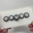
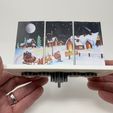
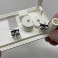
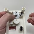
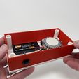
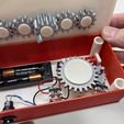
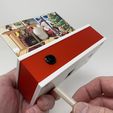
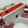
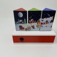
Parts.
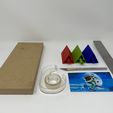
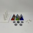
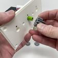
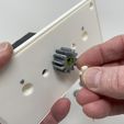
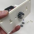
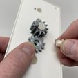
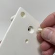
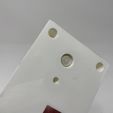
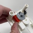
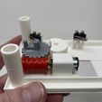
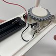
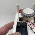
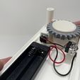
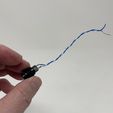
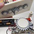
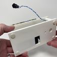
I acquired the following parts:
• One N20 150RPM 6VDC gear motor.
• One 2AAA battery pack.
• Two AAA batteries.
• Two micro lever switches (search for "CYT1073").
• One momentary push button switch (Jameco 315651 or equivalent).
• Fifteen 3mm (diameter) by 1.6mm (thick) neodymium magnets.
• Four M2 by 10mm cap screws.
• Four M2 nuts.
I 3D printed the following parts at the following settings:
• Two "Axle, Gear, Idler.stl", .15mm layer height, 20% infill.
• One "Axle, Geneva Drive and Gear.stl", .15mm layer height, 20% infill.
• One "Axle, Geneva, Driven.stl", .15mm layer height, 20% infill.
• One "Base.stl", .15mm layer height, 20% infill, with supports (touching build plate only).
• Three "Bolt, Gear, Tower.stl", .15mm layer height, 20% infill.
• Four "Bolt, Top To Base.stl", .15mm layer height, 20% infill.
• Two "Gear, Idler (1.5m 12t).stl", .1mm layer height, 20% infill.
• One "Gear, Tower, Center (1.5m 12t).stl", .1mm layer height, 20% infill.
• Two "Gear, Tower, Ends (1.5m 12t).stl", .1mm layer height, 20% infill.
• One "Gear, Worm.stl", .1mm layer height, 20% infill.
• One "Geneva Drive and Gear.stl", .1mm layer height, 20% infill.
• One "Geneva, Driven.stl", .1mm layer height, 20% infill.
• One "Skirt.stl", .15mm layer height, 20% infill.
• One "Top.stl", .15mm layer height, 20% infill.
• One "Tower, Center.stl", .15mm layer height, 20% infill.
• Two "Tower, End", .15mm layer height, 20% infill.
This mechanism is a high precision print and assembly using at times very small precision 3D printed parts in confined spaces with highly precise alignment. I printed the gears and wheels using the Ultimaker Cura 4.8.0 "Engineering Profile" on my Ultimaker S5s, which provides a highly accurate tolerance requiring minimal if any trimming, filing, drilling or sanding. However, prior to assembly, I still test fitted and trimmed, filed, drilled, sanded, etc. all parts as necessary for smooth movement of moving surfaces, and tight fit for non moving surfaces. Depending on your slicer, printer, printer settings and the colors you chose, more or less trimming, filing, drilling and/or sanding may be required to successfully recreate this model. I carefully filed all edges that contacted the build plate to make absolutely certain that all build plate "ooze" is removed and that all edges are smooth using small jewelers files and plenty of patience to perform this step.
This mechanism also uses threaded assembly, so I used a tap and die set (6mm by 1, 8mm by 1.25) if required for thread cleaning.
Tower Preparation.
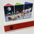
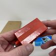
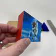
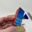
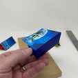
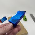
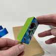
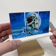
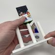
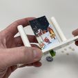
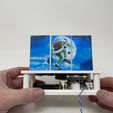
The billboard uses three towers, two "Tower, End.stl" and one "Tower, Center.stl". I chose to decorate our towers with free downloaded Christmas images. I selected landscape (as opposed to portrait) oriented images since the towers loosely provide a 5 (tall) by 7 (wide) landscape aspect ratio. I then loaded each image into a paint program and scaled each to 71mm tall by 105mm wide. Once scaled I 2D printed the images and trimmed away the excess. With the images ready, I performed the following steps:
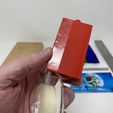
• Placed two strips of double sided thin tape on each side of the left tower (red tower as appears in the images).
• Adhered the left edge of the image to the left edge of the tower, then pressed in place.
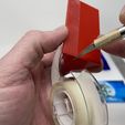
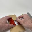
• Trimmed the remainder of the image from the tower.
• Placed two strips of double sided thin tape on each side of the right tower (blue tower as appears in the images).
• Adhered the right edge of the remaining image to the right edge of the tower, then pressed in place.
• Trimmed the remainder of the image from the tower.
• Placed two strips of double sided thin tape on each side of the center tower (green tower as appears in the images).
• Centered the remainder of the image on the tower, the pressed in place.
• Trimmed the excess from the tower.
I repeated this process with the remaining two images on the remaining two sides of the towers.
Top Assembly.
To assemble the top, I performed the following steps:
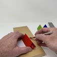
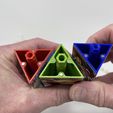
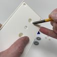
• Using a flat punch, I pressed three neodymium magnets into the left tower making certain the polarity of the magnets matched.
• I repeated this process with the center and right towers, again making certain the polarity of all magnets matched.
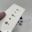
• Using a flat punch, I pressed six (two in each hole) neodymium magnets into "Top.stl" matching the polarity of the towers.
• Slid the center tower onto the top assembly.
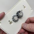
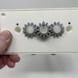
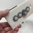
• Pressed "Gear, Tower, Center (1.5m 12t).stl" onto the center tower such that the elongated tooth aligned with the face on the tower I desired to be the initial image.
• Secured the gear in place using one "Bolt, Gear, Tower.stl" making certain the tower rotated freely.
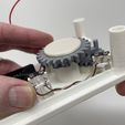
• Positioned one "Gear, Idler (1.5m 12t).stl" onto the base assembly and secured in place with one "Axle, Gear, Idler.stl" making certain the gears rotated freely.
• Repeated this process with the remaining idler gear and axle again making certain the gears rotated freely.
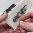
• Slid the left tower (red in the images) onto the top assembly.
• Pressed one "Gear, Tower, Ends (1.5m 12t).stl" onto the tower making certain the tower image aligned with the center tower image.
• Secured the gear in place using one "Bolt, Gear, Tower.stl" making certain the towers rotated freely.
• Repeated the previous two steps for the remaining tower (blue in the images).
Base Assembly.
To assemble the base, I performed the following steps:
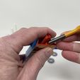
• Attached the two micro lever switches to "Base.stl" using the four M2 cap screws and M2 nuts.
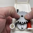
• Positioned "Geneva Drive and Gear.stl" on the base assembly, and secured in place with "Axle, Geneva Drive and Gear.stl" making certain the gear rotated freely on the base.
• Positioned "Gear, Worm.stl" on the base assembly and secured in place by sliding the gear motor axle into the worm gear motor axle hole.
• With the Geneva drive and gear positioned as shown, placed "Geneva, Driven.stl" onto the base assembly and secured in place with "Axle, Geneva, Driven.stl".
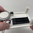
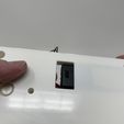
• Secured the battery holder to the base assembly using double sided tape making certain the on / off switch was accessible through the window on the bottom of the base assembly.
• Soldered a wire from the common terminal of the Geneva drive micro lever switch to the common terminal of the center tower switch.
• Soldered a wire from the normally closed terminal of the Geneva drive micro lever switch to the normally closed terminal of the center tower switch.
• Soldered the battery holder black wire to the normally closed terminal of the center tower micro lever switch.
• Soldered the battery holder red wire to the gear motor "+" terminal.
• Soldered a wire from the center tower micro lever switch common terminal to the gear motor "-" terminal.
• Soldered a 10mm length of wire to one terminal of the momentary push button switch.
• Soldered a 10mm length of wire to the remaining terminal of the momentary push button switch.
• Soldered the free end of one of the 10mm lengths of wire from the momentary push button switch to the Geneva drive micro lever switch common terminal.
• Soldered the free end of remaining 10mm lengths of wire from the momentary push button switch to the Geneva drive micro lever switch normally closed terminal.
At this point, I installed two AAA batteries in the battery holder, turned on the battery holder switch, and made certain the Geneva drive wheel rotated clockwise as viewed from the top of the gear.
Final Assembly.
For final assembly, I performed the following steps:
• Placed two AAA batteries in the battery holder.
• With the Geneva drive gear positioned as shown, and the elongated tooth on the center tower gear positioned as shown, slid the top assembly onto the base assembly, then secured in place with four "Bolt, Top To Base.stl".
• Turned on the battery pack and adjusted both micro lever switches until the mechanism stopped.
• Pressed the momentary push button switch and made certain the mechanism rotated through all three panels then stopped.
• Removed the top.
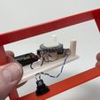
• Positioned the momentary switch in "Skirt.stl", then slide the skirt down over the base assembly.
• With the Geneva drive gear positioned as shown, and the elongated tooth on the center tower gear positioned as shown, slid the top assembly onto the base assembly, then secured in place with four "Bolt, Top To Base.stl".
And that's how I 3D printed, assembled and tested "3D Printed Christmas Billboard".
I hope you enjoyed it!

/https://fbi.cults3d.com/uploaders/13550170/illustration-file/ca30824e-c77d-405f-9670-122cff163d9a/Image0000a.JPG)
