Introduction
This thing is just a SCAD script that provide an API to manipulate parts of a models by placing them relative to each other.
When writing SCAD models i found out that the result scripts are not readable. Even when i read them myself many days later i don't understand what i wrote and why i wrote them this way.
The main reason is that i use a lot of constant values computed or measured on parts in real life and even with comments in code this is hard to read. Furthermore when i want to make modifications i don't know where to apply them in code.
This API simplify all my designs by allowing me to place parts relatives to each other.
This thing is designed using this library: http://www.thingiverse.com/thing:2005142
How it works
Boxes basics
Each elementary part of the model (cube, cylinder etc...) can be bounded by a box that you create using the api boxCreate().
Boxes faces are always aligned with x,y,z axis. The boxCreate api just take the size of the box on [x,y,z] before any rotation:
boundingBox = boxCreate ( [1, 1, 1] );
The object returned is an array on which we can get some computed values using indexes (which are all listed at the beginning or the file box.scad).
For instance these indexes returns the size elements of the box. When the box is first created these are just the values we gave:
boundingBox[idx]
boundingBox[idy]
boundingBox[idz]
The following indexes returns the position values on x,y,z of the center of the box. The center of the box is the point that we move using transformations, it can be anywhere in the box. When the box is first created the center is the barycenter of all its points and it is placed at coordinate [0,0,0]:
boundingBox[ix]
boundingBox[iy]
boundingBox[iz]
The following indexes returns the x position of the left face:
boundingBox[ixmin]
boundingBox[ileft]
The equivalences are made such you are the observer that look in the direction of Y axis with Z going top and X going right:
ixmin = ileft
ixmax = iright
iymin = ifront
iymax = iback
izmin = ibottom
izmax = itop
Transformations
The box can be translated, rotated and resized.
The object contains actualy 2 boxes: the outer box that we just saw (global coordinates) and the inner box (local coordinates).
To access to local coordinates, just add an l in indexes :
ilxmin = illeft
ilxmax = ilright
ilymin = ilfront
ilymax = ilback
ilzmin = ilbottom
ilzmax = iltop
When the box is first created the local and global coordinates have the same values. But they will differ when you use transformations:
* When you translate the box using boxTranslatexxx or boxMovexxx functions only the global box is translated, the local box stay unmodified,
* When you rotate the box using boxRotatexxx functions only the global box is recomputed in order to hold the rotate part of the local box.
* When you resize the box using boxResizexxx or boxExtrudexxx functions the local box is resized and the global box is recomputed in order to hold the rotate part of the local box.
Another way to explain this is: The global box is the bounding box of the local box after translation/rotation.
Rendering
The following APIs allow you to get SCAD modules with elementary shapes bounded in a box:
- boxRenderCube(bbox): this module builds a SCAD cube bounded in the local box, rotated and translated,
- boxRenderCylinderX(bbox): this module builds a SCAD cylinder oriented on the X axis of the local box, rotated and translated,
- boxRenderCylinderY(bbox): this module builds a SCAD cylinder oriented on the Y axis of the local box, rotated and translated,
- boxRenderCylinderZ(bbox): this module builds a SCAD cylinder oriented on the Z axis of the local box, rotated and translated,
- boxRenderConeRight(bbox, sd): this module builds a SCAD cylinder oriented on the X. The small diameter (sd) of the cone is placed on the right face of the local box,
- boxRenderConeLeft(bbox, sd): this module builds a SCAD cylinder oriented on the X. The small diameter (sd) of the cone is placed on the left face of the local box,
- boxRenderConeBack(bbox, sd): this module builds a SCAD cylinder oriented on the X. The small diameter (sd) of the cone is placed on the back face of the local box,
- boxRenderConeFront(bbox, sd): this module builds a SCAD cylinder oriented on the X. The small diameter (sd) of the cone is placed on the front face of the local box,
- boxRenderConeTop(bbox, sd): this module builds a SCAD cylinder oriented on the X. The small diameter (sd) of the cone is placed on the top face of the local box,
- boxRenderConeBottom(bbox, sd): this module builds a SCAD cylinder oriented on the X. The small diameter (sd) of the cone is placed on the bottom face of the local box.
The cylinders diameters and cone large diameter are computed as the minimum value of the borders of the cylinder's/cone's base.
Note that the resulting object is bounded by the global box.
Examples
The images of this thing is the result of the following scripts, as you can see the only scalar values are the initial bounding boxes of the items. These boxes are then moved and rotated with box API transformations and then rendered using box API modules (boxRenderxxx).
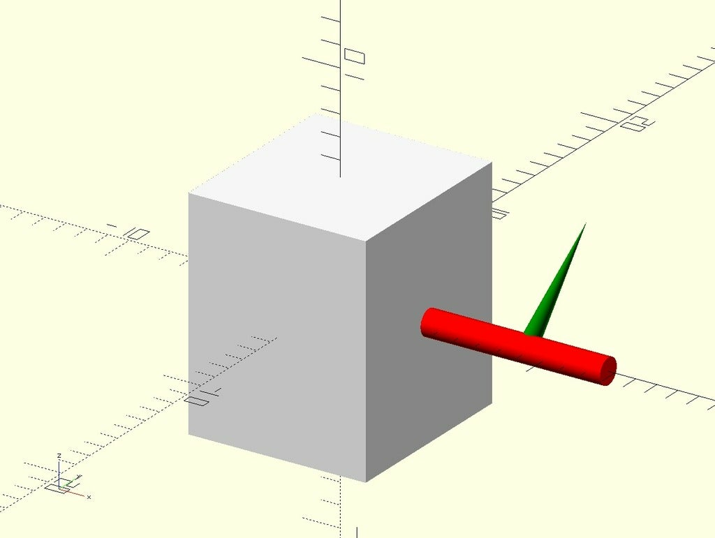
Example 1
In this scene we want the mainBox centered at [0,0,0], the cylinderX sticked to the center of the right face of the mainBox, then the cylinderY is actually a cone based in the center of the cylinderX and rotated by 42°.
include <box-001.scad>

$fn = 180;

mainBoxSize = [8.4, 9.1, 10.5];
cylinderXSize = [8.5, 1.2, 1.2];
cylinderYSize = [0.8, 5.4, 0.8];
cylinderYRotation = [ 42, 0, 0];

mainBox = boxCreate ( mainBoxSize );
cylinderX = boxMoveLeftTo ( boxCreate ( cylinderXSize ), mainBox[ixmax] );
cylinderY = boxMoveFrontTo (
    boxMoveBottomTo (
        boxMoveLeftTo (
            boxRotate (
                boxCreate ( cylinderYSize )
                , cylinderYRotation )
            , cylinderX[ix] )
        , cylinderX[iy] )
    , cylinderX[iz]
);

color ( "White" )
boxRenderCube ( mainBox );

color ( "Red" )
boxRenderCylinderX ( cylinderX );

color ( "Green" )
boxRenderConeBack ( cylinderY );
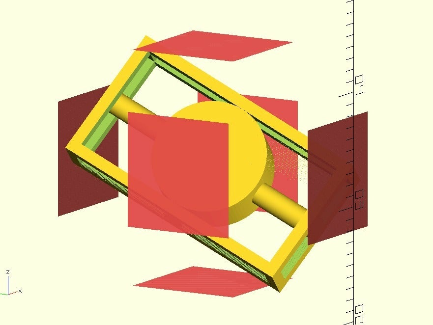
Example 2
This script generates more complex structures with still simple code:
// Test of some modules
test =
    boxRotate (
        boxMoveTo (
            boxRotate (
                boxCreate ( [2, 10, 20] )
                , [110,30,20]
            )
            , [10, 20, 30]
        )
        , [10,0,0]
    )
;
testResized = boxResize ( test, 1 );
plane = boxCreate ( [0.0001, 10, 10] );
difference() {
    boxRenderCube( testResized );
    boxRenderCube( boxResizeX ( test, 1 ) );
    boxRenderCube( boxResizeY ( test, 1 ) );
    boxRenderCube( boxResizeZ ( test, 1 ) );
}
boxRenderCylinderX ( boxResizeX ( test, 1 ), $fn=100 );
boxRenderCylinderY ( boxResizeY ( test, 1 ), $fn=100 );
boxRenderCylinderZ ( boxResizeZ ( test, 1 ), $fn=100 );
// boxRenderCylinderZ( test );
#translate( [ testResized[ixmax], testResized[iy], testResized[iz] ] )
rotate( [0,0,0] )
boxRenderCube( plane );
#translate( [ testResized[ixmin], testResized[iy], testResized[iz] ] )
rotate( [0,0,0] )
boxRenderCube( plane );
#translate( [ testResized[ix], testResized[iymax], testResized[iz] ] )
rotate( [0,0,90] )
boxRenderCube( plane );
#translate( [ testResized[ix], testResized[iymin], testResized[iz] ] )
rotate( [0,0,90] )
boxRenderCube( plane );
#translate( [ testResized[ix], testResized[iy], testResized[izmax] ] )
rotate( [0,90,0] )
boxRenderCube( plane );
#translate( [ testResized[ix], testResized[iy], testResized[izmin] ] )
rotate( [0,90,0] ) boxRenderCube( plane );