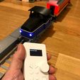
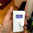
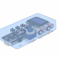
I decided to make a remote control for my 3D-printed trains, mainly becasue my son has a hard time with the smartphone interface and sencondly (and probably more important) it was fun. :)
This little NodeMCU-based box can of course be used for any other purpose as well, I've included an Arduino-project that is a wifi network scanner (also visible runninng in one of the pictures). This example can be helpful if you want to continue develop this project and for example integrate a menu where you can choose between several different targets.
This remote works with the standard software for the Hectorrail 141 and sends its commands with HTTP GET requests and basically ignores the response. This is fore sure not the most efficient way of communicating between two NodeMCU's, but this leavs the posibility open that you can still connect to the trains with your smartphone or tablet as well as this remote.
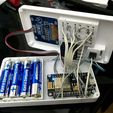
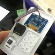
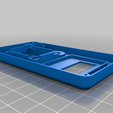
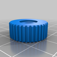
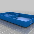
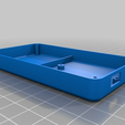
I found out when assembling that the box is a seriously tough squeeze so be careful when soldering the button legs and bend them so they take a minimum ammount of space. I've included two versions of the back side, one if you want to use individual cells and one if you want to use a battery pack. I strongly suggest the latter, even if you buy individual rechargable AAA-cells I recommend soldering them into a pack. Building a battery bay with loose cells is not as simple as it looks to get the connection good. If I build another one, I will use a soldered batterypack and drill a hole for a charging connector on the side so I don't have to unscrew the back side.
Needed equipment:
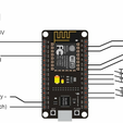
NodeMCU - A dev-board that contains an ESP8266 Wifi micro controller. This one can usually be found pretty cheap on eBay, Whish or Alibaba, just compare the picture to the schematic to see that it is the right version. https://en.wikipedia.org/wiki/NodeMCU
OLED display with 4 wire I2c connection and SH1106 controller.
http://www.heltec.cn/download/OLED_Sepecification.pdf
On page 4 in this PDF you have an overview, I use the one in the bottom right corner, 1,3" SH1106 controlled 4 wire monochrome version. It is sold at our local hardware store Kjell&Co: https://www.kjell.com/se/sortiment/el-verktyg/elektronik/optokomponenter/led-lcd-displayer/luxorparts-oled-display-for-arduino-1-3--p87946?gclid=EAIaIQobChMIuuWojpiA3wIV0qiaCh07cQFDEAYYASABEgLA9_D_BwE&gclsrc=aw.ds
NOTE! you need to install a library extension for the Arduino environment, check the Hectorrail 141 page for instructions: https://www.thingiverse.com/thing:2575667
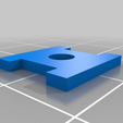
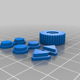
6pcs Buttons - Search ebay for "Tactile PCB push button". It should be with a medium length of the button, but if you buy the long ones you can trim them down until they work well. DON'T! glue the button frame to the main body before you have tested that the buttons work!
1pcs 5-10kOhm potentiometer. The one used here is a traditional plastic one with a long knob tha has been cut down to about 6-7mm length. The thread is 3/8" but I've just drilled the hole out to 10mm in the body, as the thread is too fine to work.
Power switch: I used a super-tiny toggle switch for this project and I cannot find it, so I recommend that you experiment a little here and if you cannot find a small toggle switch that works with the button parts included, just enlarge the hole and put a toggle switch there instead.
NOTE! the "esp8266-OLED-master" zip-file ontains the library for the OLED display, it should be placed in the libraries folder in your Arduino IDE installation, for example:
C:Program Files (x86)Arduinolibraries
The other two project directories can be placed wherever you want.

/https://fbi.cults3d.com/uploaders/16207324/illustration-file/724aeea5-f28b-4bb8-8850-516cd6b109a4/IMG_6683.jpg)
