This is all about the SKR 32Bit board and it's setup, firmware and wiring.
This is a condensed tutorial there's much better out there such as Vanessa_E's Instructable if you do not find what you need here. This is going to be for Windows users.
The newer SKR 1.4 board includes 2 Z plugs right on it and a slightly faster CPU. I would recommend this one going forward just for two Z outputs.
Here's BTT's own guide on the SKR 1.4. This is very complete, check it out!
BIQU also makes a board just for the Ender3. The SKR Mini E3 it's size and pin compatible with the stock ender board and has integrated TMC2209.
Also direct from them is the cheapest I have found the boards. They have a combo package too if you can wait for the shipping.
#Note
on Anet screens:
They will not work with this board. Anet screens are not wired to the regular standard and are 5v. These use 3.3v logic. Use a 12864 or 2004 RepRap type screen.
That said, Let's dive in!
#Requirements
#Optional
- LV8729 or other driver for extruder
- LCD12864
- Many LCD options supported!
#Getting
Started
First thing download and install VSCode. Once installed you need to add Platform.io to it.
Open VSCode and select the cube icon on the left

At the top you will see a search box. Type in "platform" and select install on Platform.io IDE

It can take a few minutes to install and may ask you to reload, Do so and it's ready to go.
In the left column again select the first icon that looks like sheets of paper. This is our workspace. Here select "Add Folder" and browse to the unzipped Marlin firmware you downloaded. Make sure you go to the folder level with the platform.ini in it.

Your workspace should now look like this with the Marlin FW files loaded.

The first file we need to edit is Platform.ini. Select this in the list and it will load into the workspace editor. Find the line "default_envs" right near the top and change it to "LPC1768" as shown.
Now if you have the SKR 1.4 Turbo this needs to be set to LPC1769.

- Save this with CTRL+S and lets go to the Marlin folder from the list in the left column. Select Configuration.h to load it and let's start setting up your machine here.

Here's where you will make most of the needed changes for your machine. Start at the top and work your way down setting up your options.
#SKR
Set the first serial port to "#define SERIAL_PORT 0"
You need to remove the // in front of the line "#define SERIAL_PORT_2 -1" to uncomment it.
For SKR 1.3 set your MOTHERBOARD to "#define MOTHERBOARD BOARD_BTT_SKR_V1_3"
For SKR 1.4 set the MOTHERBOARD to MOTHERBOARD BOARD_BTT_SKR_V1_4 and for the Turbo version use MOTHERBOARD BOARD_BTT_SKR_V1_4_TURBO
#MKS
#SKR
1.4 and SKR 1.4 Turbo with BLTouch special note!
With this setup in order to use the special BLTouch header on the board you need to make a few small changes:
In configuration.h comment out the line: #define
Z_MIN_PROBE_USES_Z_MIN_ENDSTOP_PIN by putting // in front of it.
In \Marlin\src\inc\conditionals_LCD.h search for the line "#define HAS_CUSTOM_PROBE_PIN"


#Restart
VSCODE to load changes!
#Marlin
General
Now I am assuming you have some experience with Marlin FW here. You need to set things like your filament diameter, number of extruders, thermistor types, bed leveling if you have it and so on. This tutorial is not meant to go in depth on these settings. You can also use the included example configs in Marlin but make the above changes per your board.
Now you need to set your Stepper Drivers in Marlin. Uncomment and set the type for each axis you have. For TMC2208 in UART you set TMC2208 as shown.

I run LV8729 on my extruder so it is set that way.
Next we move on to Configuration_adv.h and search for TRINAMIC to find this section.

Here is where we set the steps and drive current. 800MA is pretty typical and you can leave it here on most machines. the MICROSTEPS is the step divider. On this machine I run 32 but 16 is more typical. This effects your STEPS_PER_MM. I would leave at 16 for most cases.
Moving down you will find "//#define HYBRID_THRESHOLD". Remove the // in front of this line and let's set this up.
What this sets it the speed it switches from Stealthchop to Spreadcycle. This helps with high speed moves where Stealthchop can easily skip steps. I set this to 50. This keeps the machine nice and quiet for most moves but provides the needed torque for fast direction changes.

This should be all the changes you really need to make in the firmware.
#Compile
the Firmware
To compile press CTRL+SHIFT+B to bring up the build menu.

Select PlatformIO: Build as shown and it will start to compile. This should take a few minutes to complete and you will see a readout of what's going on in the terminal at the bottom of the VSCode window.
If everything is right it will show a message like this:

Once it has successfully compiled you can right click on the .pio folder and hit "Reveal in explorer" to open it in file explorer.

Dig down into that folder to the LPC1768 folder, same as your processor. Here you will find the file firmware.bin. This is all we need to flash the firmware. Copy this file to the included micro SD card and insert it in the board. Once it's powered up it will load this file and rename it to firmware.cur.

#Installing
the board
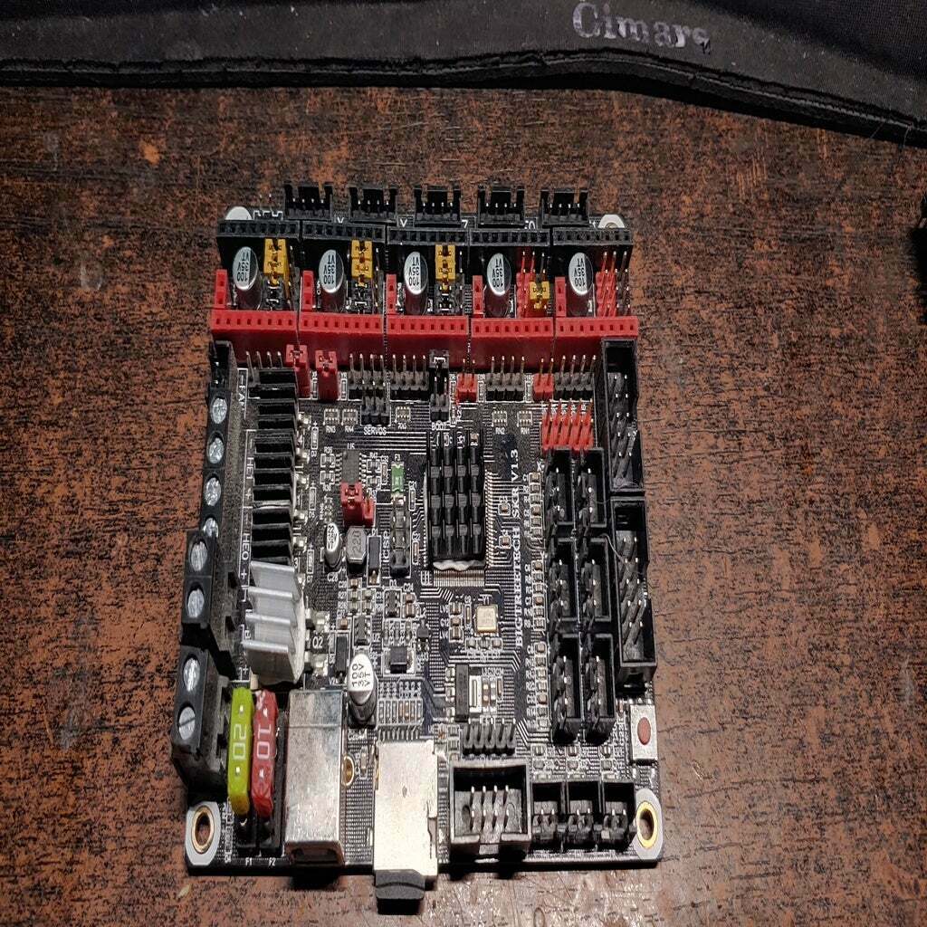
On your SKR board, which I will be using as my example here, You have 5 stepper driver slots with jumpers under them, a row of jumpers spaced out along the front and more jumpers across the board. Let's have a look at what these are.

Here you can see the purpose of these jumpers. Since I run 3 stepper drivers that are TMC2208 those have the jumpers set for UART control. The 4th jumper has it set for 1/16th steps with a LV8729. There are 4 jumpers instead of 3 like on RAMPS so only the first 3 are used to set steps. To set steps on a non-UART or SPI driver remove the jumpers as usual.

Here is the board with stepper drivers installed for reference.
The colored band along the stepper pins match with the colored header on the board for correct installation. Still check with your drivers to be sure this matches.
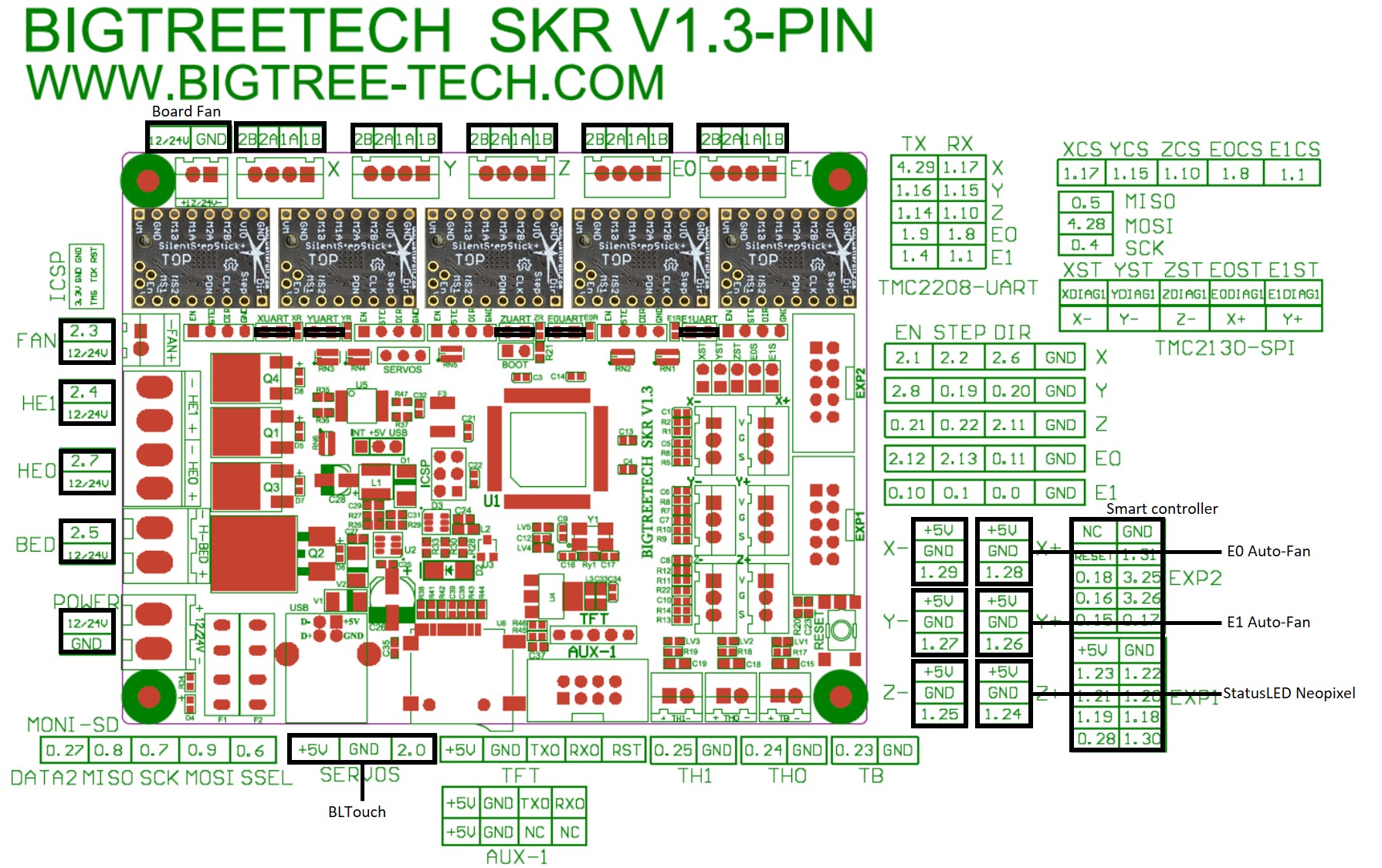


Next we can attach the power and heater wires.

Here I have marked the polarity of the pins as well. Please pay close attention to this as it flips from the power connector to the others.
Here's the stepper driver locations and output. These boards only have a single Z output but there's inexpensive dual output adapters you can pick up to run your dual Z motors easily.

#Endstops
and Thermal Sensors

Here's the connections for the endstops, thermals and LCD AUX. On some machines the endstop wires might need to be swapped around to match the board.
If you use a standard LCD12864 then the wires connect as usual!
#BLTouch
Wiring
For the BLTouch there's a separate header for the servo signal.

This little connector is just for servos. This is where the 3pin BLTouch connector hooks up if you use one.
#I think that's it!
Send me a message or leave a comment if I missed something. I hope this helps!
#Thank
you!
:format(webp)/https://fbi.cults3d.com/uploaders/16051940/illustration-file/574d07bc-9718-4b8a-89fc-a570762642a2/20191226_063334_HDR.jpg)


/https://preview3d-images.cults3d.com/9npx8fk0510g3qtrbjpal3eb1cf5)
/https://preview3d-images.cults3d.com/y27gfqjivw6zsmuewjxtgvww0ycd)
/https://preview3d-images.cults3d.com/7u4xw877p6q7ifv3bl0hik7258t9)
/https://preview3d-images.cults3d.com/11v0wsgj7y4zjzj90w7emqir73dn)
/https://preview3d-images.cults3d.com/2k98h6wapc6u67bitnqdhibt0y2f)
/https://preview3d-images.cults3d.com/4dh0llzpk3fvqdr740v9e281rhin)
/https://preview3d-images.cults3d.com/vfaex5r3yaavve1q0t8nb31499rf)


