Do not start disassembling your print bed before you have all the printed parts ready. Start with the 3-point levelling parts (http://www.thingiverse.com/thing:84754)
Obtain a Prusa MK2 heated bed and 12V and >15A power supply as per instructions in (http://www.headfuzz.co.uk/ultimaker-headed-bed). You don’t need the MDF sheet, we will attach everything to the glass plate. Note that these instructions are for attaching the heating element to a glass bed WITHOUT DRILLING.
Additional parts:
1x thermal fuse >15A, 216C (Jaycar or Farnell)
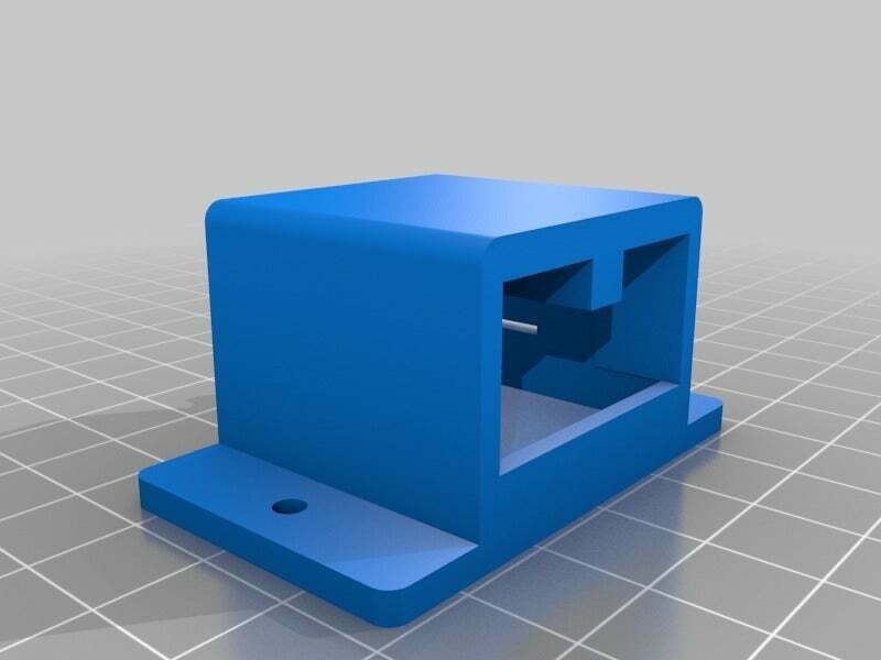
1x relay fixture/clamp (printed)
1x 240mmx240mmx5mm tempered glass (have the sharp corners rounded and edges chamfered)
4x M3 blind nuts, flat base if possible, but pronged ones are fine too (from hardware store or model shop)
4x M3 5mm bolts or screws (from hardware store or model shop)
2x M3 10mm bolts (from hardware store or model shop)
2x M3 nuts (from hardware store or model shop)
2x 250mmx75mm nailing plate (from hardware store, cut down to 240mmx75mm, can be narrower)
1x 5mm thick natural cork tile (from hardware store, make sure it is untreated natural, otherwise heating will make it release fumes!)
4x thin cable ties (from hardware store or model shop)
3x pairs of T plug (Deans) or similar high amp connectors (eBay or model shop)
Super glue (from hardware or model shop)
Super glue accelerant (from hardware or model shop)
Assembly Instructions:
First of all, have your 3-point levelling sorted out, you don’t want to fiddle with the heated bed afterwards.
I am assuming that the Prusa MK2 heating element/bed is used. Wire it according to http://www.headfuzz.co.uk/ultimaker-headed-bed, with a slight difference; connect the thermal fuse in series to the heating circuit with the thermal fuse to be taped or cemented under the printing bed close to the heating element. My pictures don’t show it as I just decided that I should place one just in case the controller fails during prints. I think that this is a good precaution to take with any such device that can cause fire in case of failure.
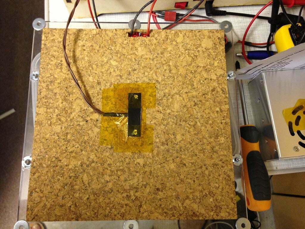
Cut the cork tile to match the heating element’s size and blank out the regions where the thermistor and the power terminals go.
Solder the power leads, LED and resistor to the marked side of the heating element; make sure the solder doesn’t protrude from the other side.
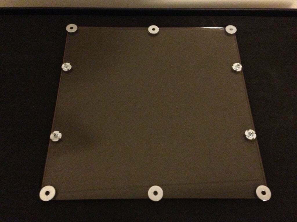
Position the heating element on the glass print bed (print side down, 3-point washer seats up). I had to reposition my 3-point washers, the superglue hold was so strong that I couldn’t remove them even with the unbonding compound! So, I have 3 washer seats on the picture…
Mark the location of the heating element with a felt marker to make it easy to reposition when securing in place.
Pass the power leads through the masked out window of the cork tile and position the cork tile on top of the heating element.
Don’t glue anything yet! There should be just enough space to position the blind nuts next to the heater/cork sandwich, two on each side. These will hold the nail plates. I placed the nail plates sideways because I didn’t want the cables to fret against, but you can put insulation tape if you want to place them back to front.
Calculate the exact distance between blind nuts from one edge to the other. This is very important to avoid unnecessary stress on the later glued joints! It can be a little larger but not smaller, the base of the blind nuts should NOT slide under the heating PCB!
Drill 2 3mm holes at the calculated distances centred on each nail plate. To make it easy, only mark the hole location on one of the plates, dent the centre with a nail, then drill. Use the first plate as a template to drill the second one.
Nail plates generally come with a slight bent as they are cut from rolled sheets, so we will use this to our advantage as a springing effect and position the nail plates to have the concave side up. Once screwed in place, the plates will be flush, otherwise they will bulge at the centre.
Do not glue the blind nuts yet!
Most blind nuts come with prongs, which is fine, but those are probably made by press-forming the base, so the base may not be perfectly flat. File off the base few times to make it flatter, then with fine sanding paper to make it smoother.
Now, fix the blind nuts to the nail plates with M3 screws loosely, they should be able to dangle. Make a trial run at positioning the nail plate and the blind nuts in place. When you press the edges, the blind nuts should land flat on the edges of the glass bed.
Clean the recipient locations with alcohol (medi-swabs) to remove any fingerprint grease then proceed with the following.
The gluing step could be tricky depending on how quick your superglue takes hold and how good you are at quickly performing the positioning process.
Option 1: Fast & Quick
1. Brush some superglue accelerant on the surfaces where the blind nuts will be glued.
2. Place superglue on the back of the blind nuts as they are still loosely attached to the nail plate, don’t get any in the threads.
3. Make sure the cork/heater sandwich is in position.
4. Place the curvy side of the nail plate on the cork, line up the blind nuts to their respective positions, then press on them simultaneously and quickly. The superglue should take hold instantaneously due to the accelerant.
Option 2: Cautious & Prudent
1. Place superglue on the back of the blind nuts as they are still loosely attached to the nail plate, don’t get any in the threads.
2. Make sure the cork/heater sandwich is in position.
3. Place the curvy side of the nail plate on the cork, line up the blind nuts to their respective positions, then press on them simultaneously. You will have couple of second to realign, depending on the speed of your superglue.
4. Without removing the pressure on either of the blind nuts, spray superglue accelerant on both locations; the superglue should take hold instantaneously. This is when you might require assistance from someone if you haven’t done this type of juggling before :).
Do the same for the second nail plate, making them evenly positioned and leaving enough space at the centre for the thermistor lead.
Now, remove all the screws and leave the glue to harden further for 5-10 minutes while you are positioning the thermistor at the centre. Be careful not to break it! The thermistor should go inside the PCB hole and touch the print bed. Bend the thermistor leads in L shape so that when the rest is flush to the cork backing’s surface, the thermistor pushes against the print bed and its back protrudes 1mm or so above the cork backing’s surface.
You might plug the rest of the hole with a tiny piece of cork, but make sure that the thermistor doesn’t get dislodged.
Tape the thermistor in place using Kapton tape.
Tape a piece of card paper (or a business card) on top of the thermistor so to bridge the gap between the nail plates when they will be in place; this will provide a flexible backing to the thermistor pushing it gently against the print bed for reliable temperature readings.
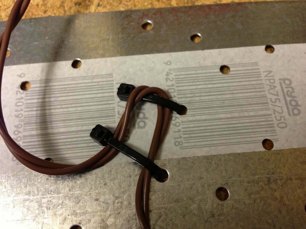
Before bolting the nail plates in place, pass the cable ties through suitable holes to loop and secure the sensor and power leads as shown in the related picture.
Carefully bolt the nail plates in position.
Use the T-plugs to connect the power leads to the relay and to the power supply. I couldn’t find an 18V relay, so I connected a 150ï— (1W) resistor in series to a 12V relay. I fixed the relay to the bottom of the Ultimaker using the fixture I printed, it may not fit all relays, but you can modify the step file if necessary.
I can'€™t believe why I waited so long to install the heated bed, the prints are simply awesome, no more warping, and very easy removal off the print bed after cooling. I was reading that parts would simply pop off by themselves after cooling, I am yet to observe this, perhaps on larger parts. Glass doesn'€™t seem to be very good at holding PLA even at 60 C, I haven't tried any higher, but coating it with Kapton tape works great. After cool down, the only think holding the piece in place seems to be the residual surface tension, which breaks away with quite little force.
Happy printing!
Addendum:
I just added two more pictures, one showing how to connect the thermal fuse; as I couldn't find a thermal fuse with 15A capacity, I connected two 10A in parallel, right next to the heating element's terminals. Note that is NOT in parallel to the heating circuit, this would just short the power supply! The compound thermal fuse is in SERIES with the heating circuit. You will have to carve out a pocket in the cork backing to accommodate it.
As a second thought, instead of using just 2 blind nuts per nailing plate, you might consider 4. If not, consider reducing the curvature of the nailing plates to reduce springing force. Ordinarily super glue is quite strong at holding glass, but one of the blind nuts popped off last night, maybe it wasn't flush enough. Anyway, use the strongest super glue available, preferably those specifically for glass/metal.
:format(webp)/https://fbi.cults3d.com/uploaders/14496464/illustration-file/d1462d7e-d4a6-4a23-bdc6-8c720b43fc45/IMG_2121.jpg)


/https://preview3d-images.cults3d.com/v7w4tpcy5w9vze857gg286hev3n1)


