Hey all SHENKOE here and I thought I would share what I use to calibrate the Steps/mm, surface quality, material flow rate, backlash artifacts, and tolerance for my machines. Now there are many test out there, many tests that my do this and do it faster, but not all are created equal. Calibration cubes are too small to accurately correct larger prints.
*** This test is best used for calibrating the steps of your printer for greater accuracy regarding the X and Y axis. (THAT MEANS YOU SHOULD ONLY USE THIS WHEN YOUR MACHINE IS RELATIVELY PRECISE IN ITS MOVEMENTS BUT COULD STILL BE BETTER). The other parts it test are there due to the design of the model and its available features. The secondary test can only be done if the test is completed, but it is not required to run the full test. As we only need the X and Y for this tests true intent.***
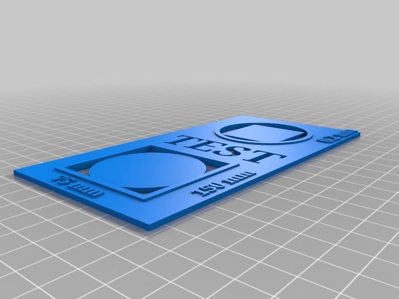
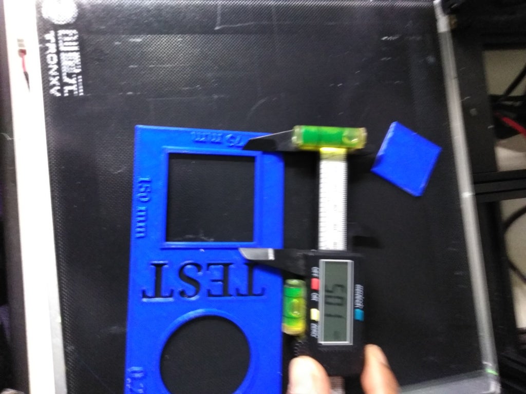
I created a larger scale test that I find to better assist in getting greater dimensional accuracy. I created this test a few months ago (printed in blue), for personal use and it has not been tested by anyone but myself since then. Recently I had adjusted my belts tautness and noticed certain things did not measure out correctly to fit other parts. THAT IS A PROBLEM!!!, as I design a lot of parts for personal use and that join or are fitted to other printed or existing parts.
So I broke out my handy dandy test card, and noticed on larger parts I was overstepping by roughly 4mm on the axis, that my friends is a very big problem. See attached photos the one in blue is the first time I had ever ran the test and well the machine barely need any adjustments, YAY ME! ( had previously calibrated my machine through different means)
#PRINT
SETTINGS#
0.16mm Layer height
10% infill
Your printing best average speed for accuracy
** Best temperature for quality**
2 walls, 2 bottom layers, 4 TOP LAYERS (4 TOPS LAYERS IS IMPERATIVE TO A GREAT TOP SURFACE)
This is thin (low z height) test, but my no means is a short one in regards to print time. Uses as little filament as possible. I printed these at 0.16mm Layer Height and at 60-80mm/s (I average about 70-80mm/s default print speed). At 0.16 layer you end up with 18 layers needing to be printed. But as long as the it has roughly 15 or more layers you should have now problem.
I would use a higher layer height, but I wanted to have this printed for quality and printability of the raised lettering on the surface. This also allows the print to fix the “squish” error related to the first few layers being pressed against the build surface. Which doesn’t correct itself for at least the first 5-8 layers, basically any time after the infill as started.
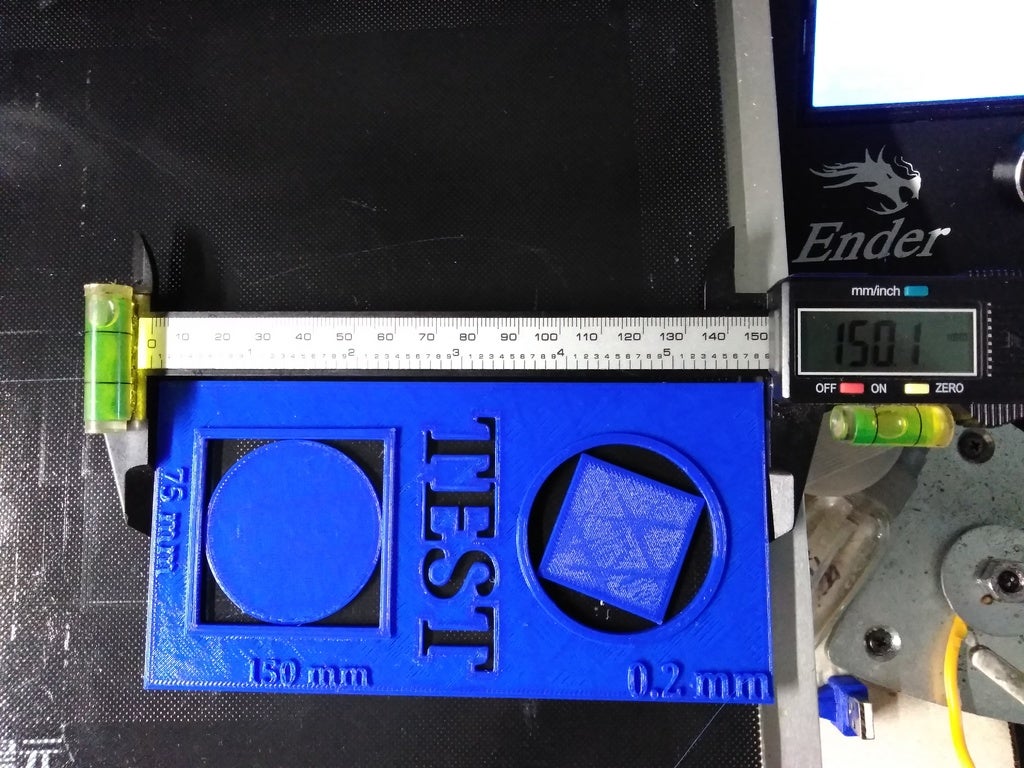
When complete the center square and circle should be basically printed in that when you remove the main body they stay stuck to the bed, there is very little room between the main body and the center bodies, I am not sure the exact tolerance of the space between the bodies, but I believe it is roughly 0.2-0.5mm. The circle will be the true identifier for the tolerance, as it has more surface are that can possible make contact with the main body, opposed to the pointed corners of the square.
I created a larger scale test that I find to better assist in getting greater dimensional accuracy. I created this test a few months ago (printed in blue), for personal use and it has not been tested by anyone but myself since then. Recently I had adjusted my belts tautness and noticed certain things did not measure out correctly to fit other parts. THAT IS A PROBLEM!!!, as I design a lot of parts for personal use and that join or are fitted to other printed or existing parts.
So I broke out my handy dandy test card. And notice on larger parts I was overstepping by roughly 4mm on the axis, that my friends is a very big problem. See attached photos the one in blue is the first time I had ever ran the test and well the machine barely need any adjustments, YAY ME! ( had previously calibrated my machine through different means)
#HOW
IT WORKS#
STEP/MM CHECK
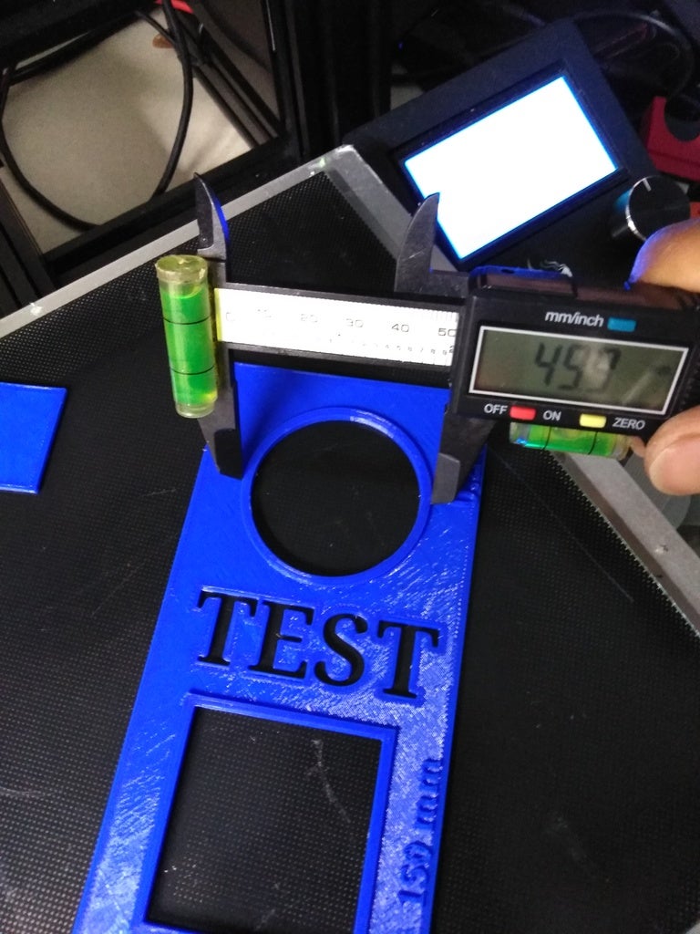
So basically place the model either along the x or y axis, I recommend the axis that is less accurate, and print. When complete all that is needed is to take some calipers and measure the following,
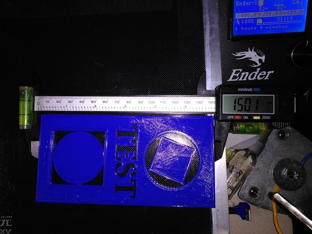
The 150mm length side
The 75mm length side
The center (raised) 50mm circle and square
The square and circle in the center of the raised (diameter of the circle should be 45 and the square from point to adjacent point should be 45mm. If measure from the side it will not be accurate.)
The thickness (z axis height) of the main body should be 2mm and overall height should be 3mm (raised surface down to the base of the print)
After you have measured the outer x and y axes lengths, take the proper step to calculate and enter then in either your terminal of choice, you firmware config files, or in your gcode. (Too many easily found guides that show and detail the process, so I’m going into that. This informational is long enough, without things that be easily referenced with a web search)
**DO NOT CONFUSE BACKLASH ARTIFACTS WITH INCORRECT STEPS/MM**
The long run of the x and y are what are truly important. But it’s good to check the center designs and parts of accuracy, as they can detect backlash on the printer, meaning if something is loose your circles will not be, well, circles. They will cause the tight tolerance of the design to fuse the edges or even overlap lines that should not be
Hence how this model can test for tolerance and backlash.
Backlash is a little more difficult to resolve (well not difficult but at least a lot more involved, as you must determine the axis that has the backlash and either tighten belts and/or bolts and what not for machine.
**SURFACE QUALITY**
Surface quality is checked the same as any other, can you see the infill through the top layers. This effect is called “Pillowing” basically the filament is too hot and due to the sparseness of some infills and lower densities, and in turn sags or slight raised were it doesn’t touch the infill. BUT WAIT!!!! A few things can be checked here.
First your cooling and print temps will have the greatest effect on the surface quality of your prints. Try knocking down the temp by 5°c and that normally takes care of the issue, unless you are it waaaay too high. Personally print at 215°c with all of my PLA due to my steel nozzle, and my fan runs at 80%.
This usually resolves the issue of poor surface quality (in my experience), though I have another setting that is standard across all my material, based on the printable average speed for the material type. That setting my friends is top layer speed!!! This little setting is, IMO, undervalued and understood. Many believe “slow and steady” on the surface will grant you the best results. I have to disagree, as I have my top surface speed set by default on all my profiles (for PLA) set to 60mm/s.
“Are you serious???” Is what some of you are probably saying, due to when you adjust other setting in, let’s say Cura, it doesn’t really get over 40mm/s when auto adjust based on the default print speed. These lower speeds work well, but are not perfect. My goal with top surfaces is to get the filament out fast and away from the nozzle and cooled just as fast. This in turn has given me some of the best surfaces I have ever seen (without Ironing). “Is it as smooth as ironing?” Not by a mile. But at this point it you wouldn’t need, it unless that is the texture you are needing.
OH!!! Almost forgot Material flow rate, now this will play a part in a couple areas. First it will affect your tolerance between parts, surface quality (all sides top, bottom and sides), and adhesion of the layers and to the bed. If you surface are uneven and/ or rough, but everything else is spot on no matter what. I would recommend one or both of the next.
E steps could be incorrect, go through the motion required for correcting that, here is a link (not going into detail as this should be done when you first get the machine IMO).
Second would be flow rate, or how quickly the material is pushed out of the nozzle. If you are pushing more than the required amount, yet your E steps are correct. Then dial back the flow rate by 1.5 - 2% each adjustment. This is due to some material being less viscous than others and flow a little more easily at the same temps as other do. So we adjust the flowrate to compensate, and do so until we get the results we want.
Enjoy the test, if you want to use this to recheck after your adjustments. It isn’t really needed to print to whole thing to completion. Print until it gets to about the 5th or 6th layer (maybe the 10th to be same). Stop the print and measure the x and y axes again.
*Again this test is best used for calibrating the steps of your printer for greater accuracy regarding the X and Y axis. The other parts it test are there do to the design of the model and its available features. The secondary test can only be done if the test is completed, but it is not required to run the full test. As we only need the X and Y for this tests true intent, but i would let the print complete every time to get all conclusive results available, in a single print. *
:format(webp)/https://fbi.cults3d.com/uploaders/15045028/illustration-file/285268ad-0083-4e4a-a0a6-8d8eb089a681/IMG_20190525_140733.jpg)


/https://preview3d-images.cults3d.com/oc905mx5rw71n83a3x8fckbrv9ib)


