Similar Models


PSP PiStation Portable Free 3D print model
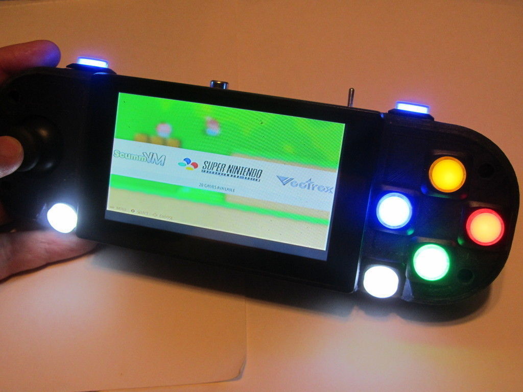
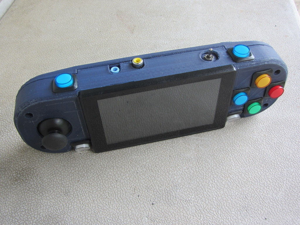
This is my Retropie Portable implementation. I put it together as a design challenge, a chance to learn more about using the Raspberry Pi, and to have a fun hand-held battery-powered gaming console.
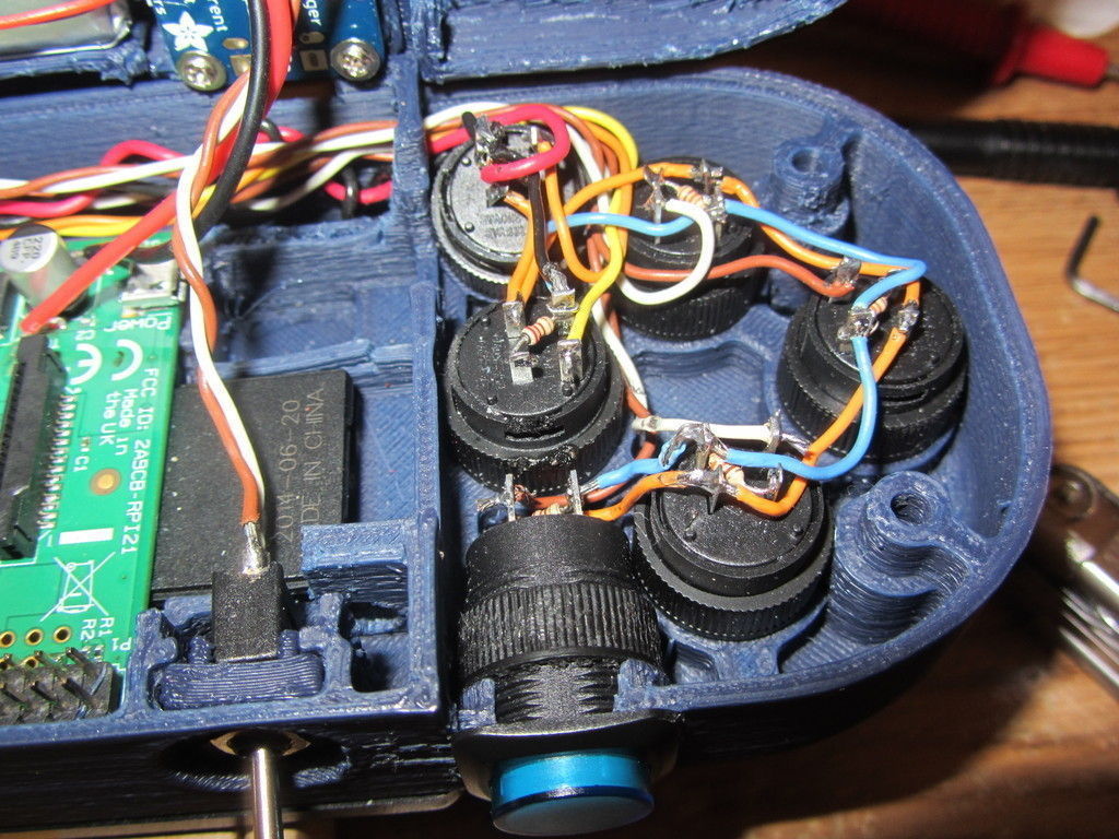
My main design goal was to have good ergonomics. This design fits nicely with my large hands, with an analog joystick that I find more comfortable than a D-pad. I really didn't like the feel of the little tactile membrane buttons everyone else is using, so I opted for these nice 16mm illuminated mechanical pushbuttons instead. They have a really smooth action, feel much nicer for prolonged play sessions, and have the additional bonus of being panel mount instead of PCB mount which makes fitting them in the case simpler.
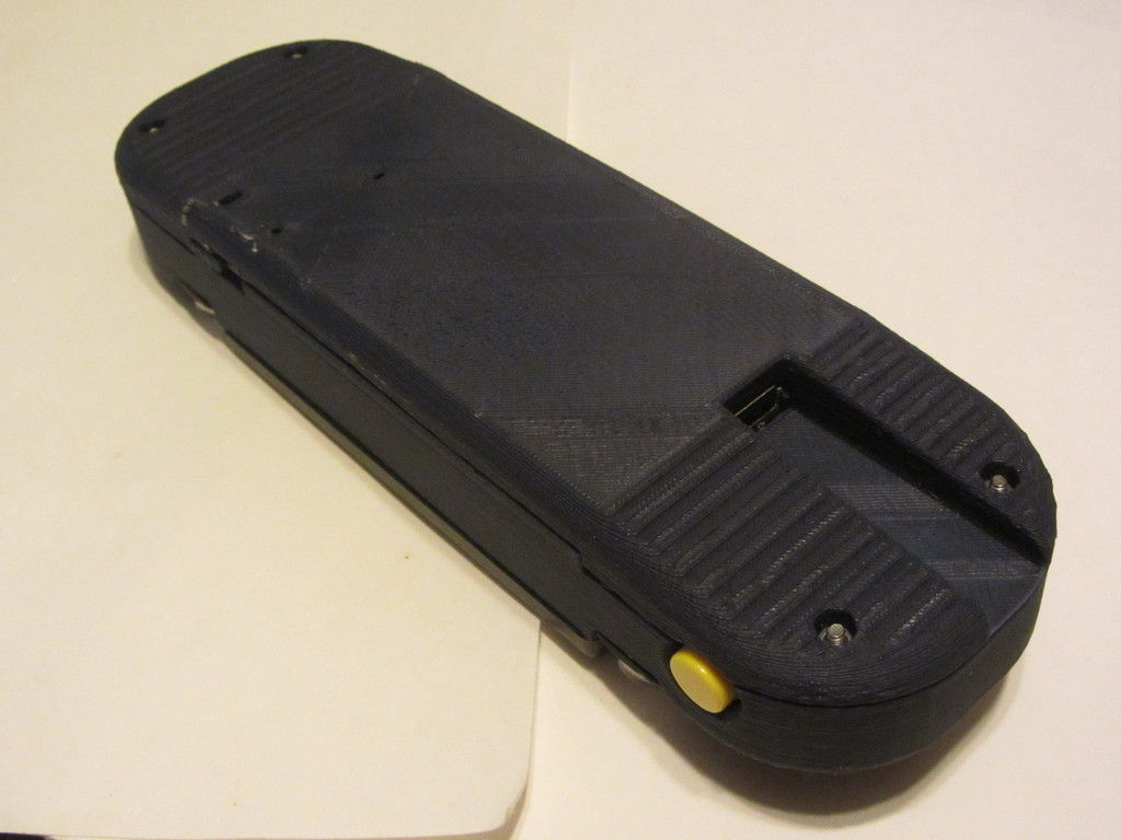
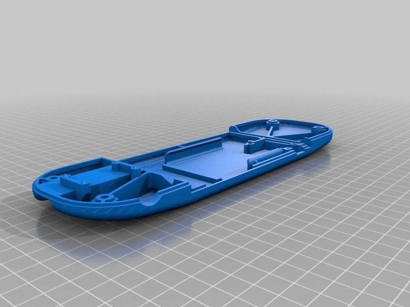
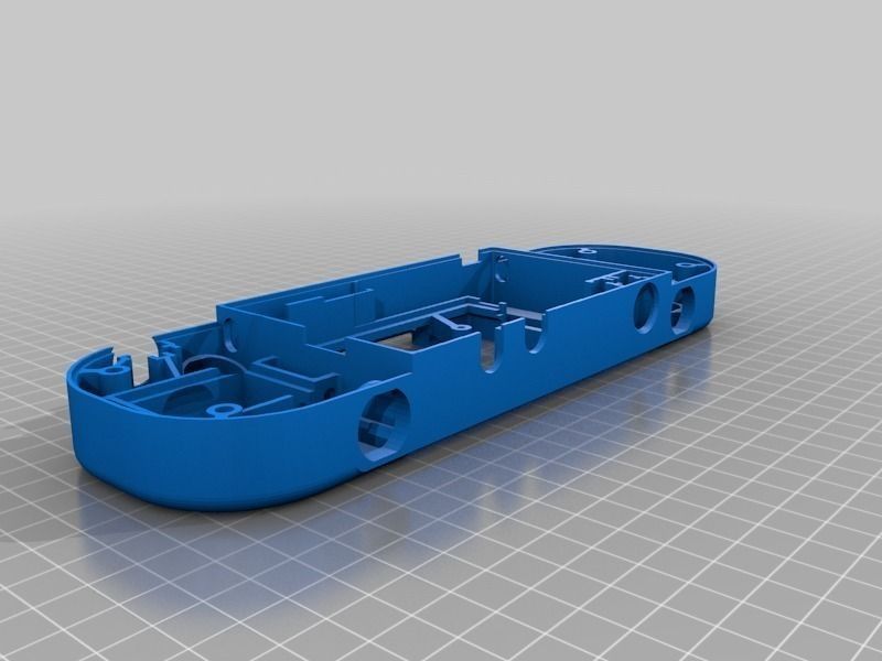
There are only 2 pieces to print with this design. Admittedly, they are large pieces, about 240mm wide. Mechanical assembly is simple, nearly all the electrical parts attach to the case with small self-tapping screws, most of them to the front half with just the battery and charger board attaching to the rear.
It has an internal battery charger, and can be played while charging - although you will discharge faster than you charge, so you still need to shut down to recharge fully. The second USB port on the PI is accessible, so you can plug in a USB drive to transfer roms, or an external keyboard for configuration or emulating systems needing a keyboard.
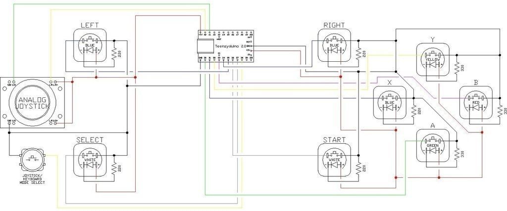
I'm using a Teensy 2.0 for the joystick function. There is a mode switch button which can be used to switch the teensy into a keyboard emulator mode that maps the joystick to arrow keys and the various buttons to certain keypresses, so you can navigate the file transfer utility and some of the other configuration menus without needing a keyboard.
No internal speakers - the amp was drawing too much current and the speakers were hard to fit, so I decided to make it headphone-only.
I wouldn't recommend that anyone build this as is and am uploading it for reference purposes. There are a handful of things that I'm not happy with that would be fixed on a redesign. For one thing, I'm using an original model Raspberry Pi B for this, while a new design should be based around a Pi 2.
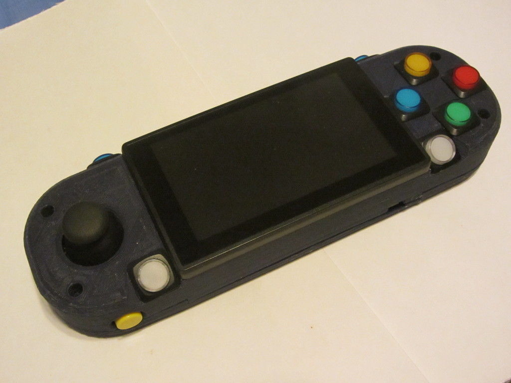
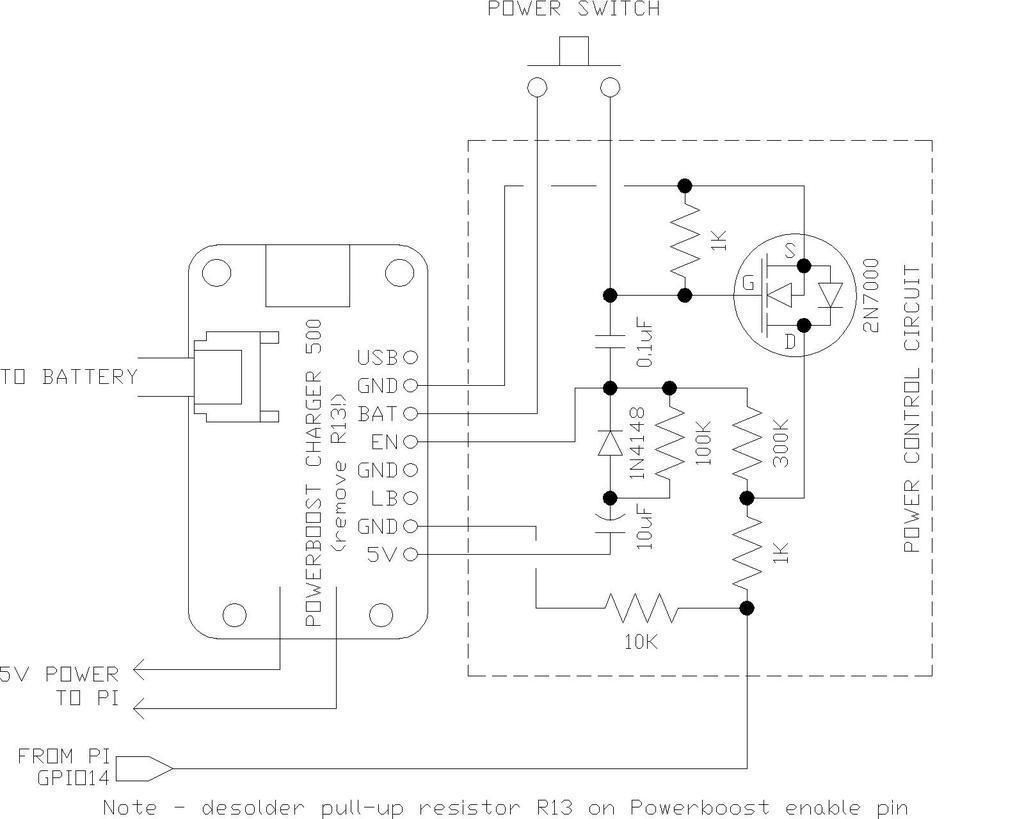
These pictures were taken before I had the soft power control circuit working. Since then I have replaced the toggle switch with a button and included a circuit to turn power on by button-press and off when the Pi shuts down. A schematic is included.
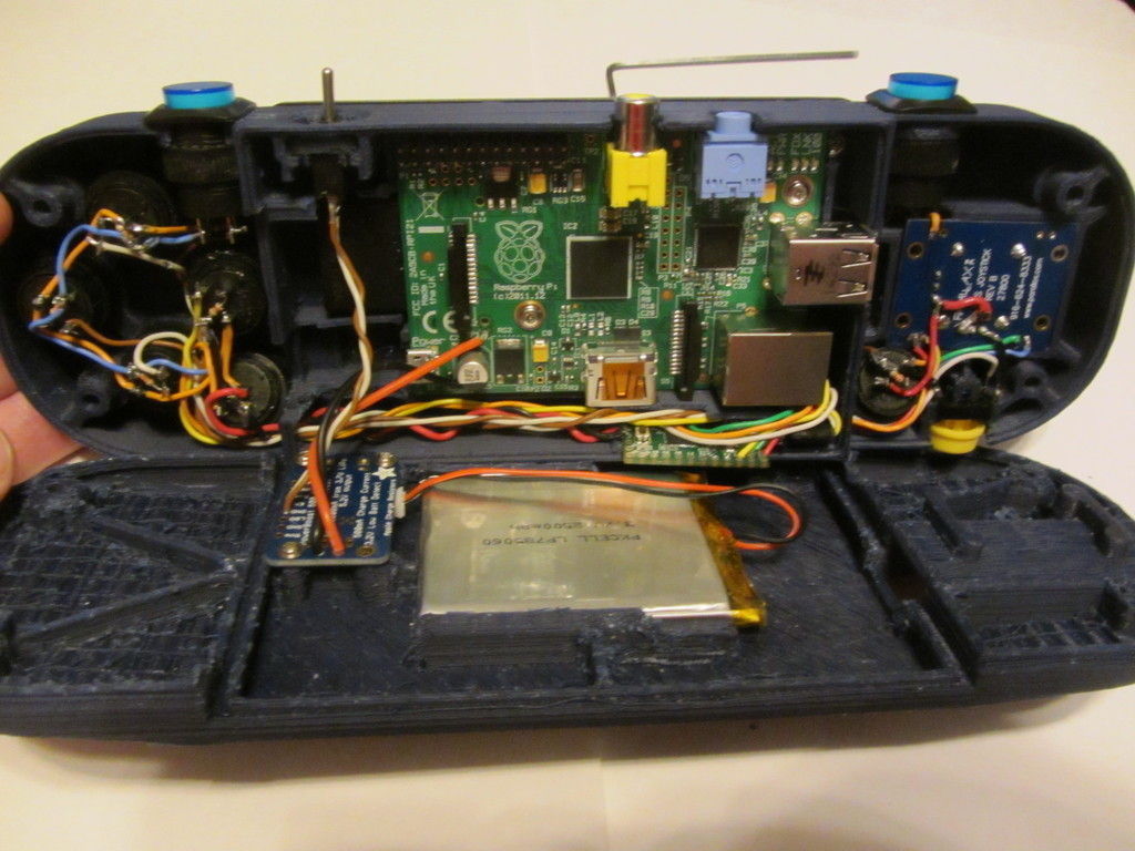
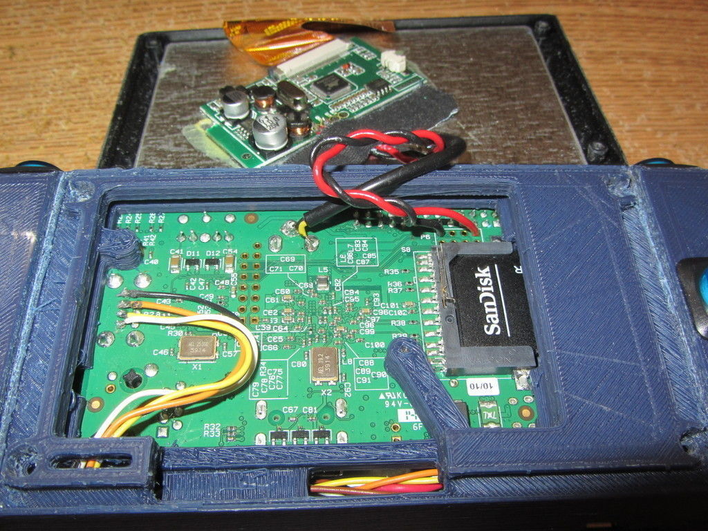
In order to fit everything in the space behind the display, I had to forgo connector and solder wires directly to the back of the Raspberry Pi. Between that and all the wires to the illuminated pushbuttons, this is not a design to attempt unless you're very comfortable with a soldering iron.
The case is nearly 240mm wide, so you'll need a large bed printer to print it. It barely fit on my 250mm circular bed. Both front and rear case halves will need to be printed with support.
InstructionsParts I used:
1 printed front case half
1 printed rear case half
RaspBerry Pi Model B: https://www.adafruit.com/products/998
Teensy 2.0: http://www.adafruit.com/products/199
Battery: https://www.adafruit.com/products/328
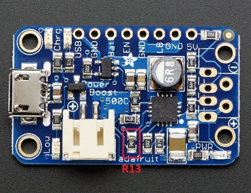
Powerboost 500 + charger: https://www.adafruit.com/product/1944
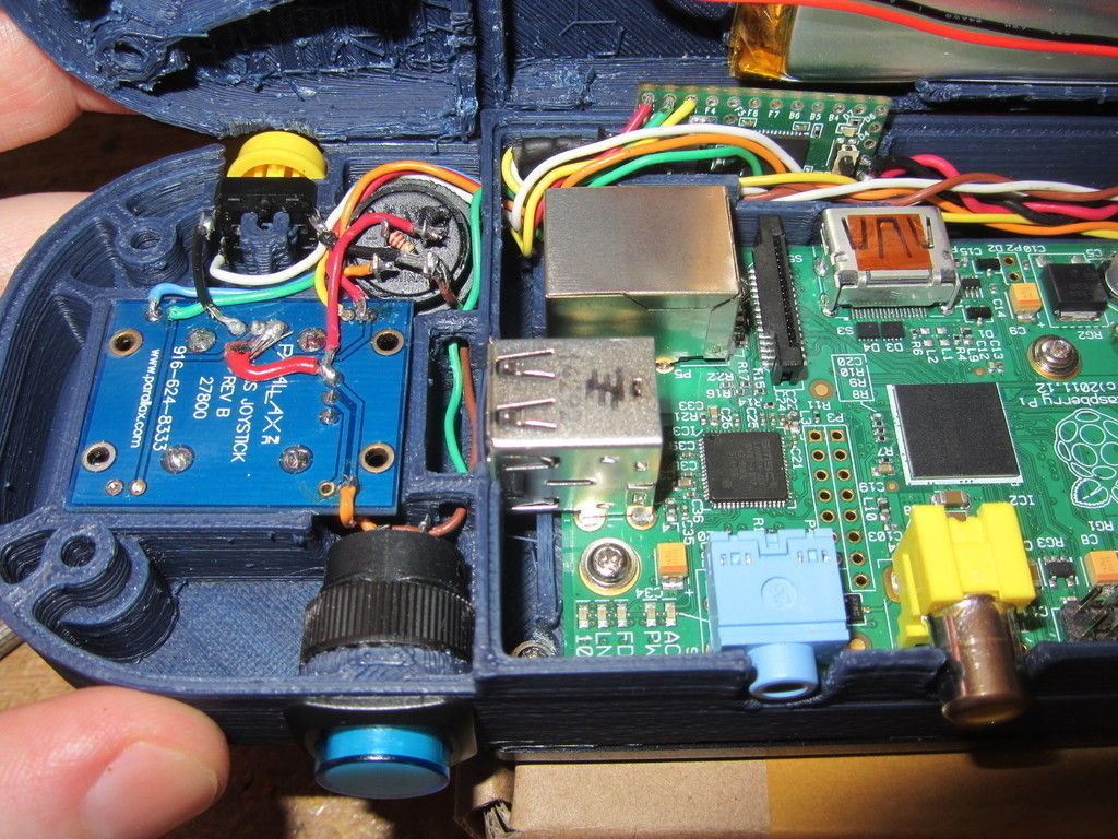
2-axis analog joystick: http://www.adafruit.com/products/245
Illuminated pushbuttons:
2x white: http://www.adafruit.com/products/1479
1x red: http://www.adafruit.com/products/1439
1x green: http://www.adafruit.com/products/1440
1x yellow: http://www.adafruit.com/products/1441
3x blue: http://www.adafruit.com/products/1477
I also used two non-illuminated buttons from this pack of 15: http://www.adafruit.com/products/1009
8gb SD card from amazon or anywhere else really
4.3TFT Display: nofollowhref=http://www.amazon.com/gp/product/B005CFLMNC">http://www.amazon.com/gp/product/B005CFLMNC
The toggle switch show in some of the pictures is not included in the final design, being replaced by a button along with the new power control circuit attached to the Powerboost 500. Note that you will have to desolder one part on the Powerboost board to use the included power control circuit.
Five 220 ohm 1/8W resistors for the blue and white illuminated pushbuttons, and three 330 ohm 1/8W resistors for the red, yellow, and green illuminated pushbuttons.
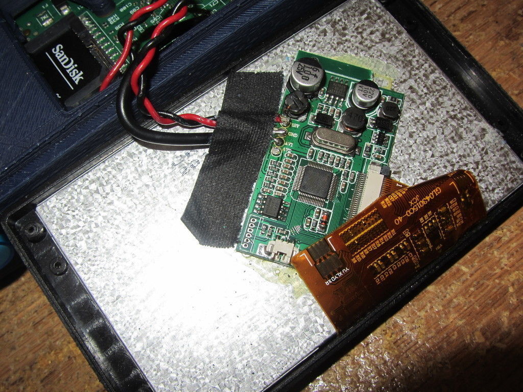
The display was modified by removing the stand, rear case, and small board with pushbuttons. I also desoldered the cable off the main board and replaced it with wires soldered directly to the back of the Raspberry Pi for power and composite video. The display I used seems to be able to run directly off 5V without modification and I have it taking power directly from a header on the Pi.
For the connection between the Teensy and the Pi, I cut an old USB cable in half and soldered wires directly to the USB connector pins on the underside of the Pi. Note that this has to be done to the 4 pins closer to the edge of the board to get the lower USB port, leaving the upper one free for an external USB device.
The Teensy is wired to the joystick, 8 illuminated pushbuttons, and 1 non-illuminated pushbutton. Connections are as follows:
Analog 0: x input from joystick
Analog 1: y input from joystick
Digital 0: A button
Digital 1: X button
Digital 2: Y button
Digital 3: B button
Digital 4: R button
Digital 5: L button
Digital 6: Start button
Digital 7: Select button
Digital 8: mode select button
The display screen, the Raspberry Pi, and the Powerboost are held in place with small self-tapping screws. I use the ones that come with the micro servos my robots keep going through since I have a lot of them spare. The front and back of the case are held together with four M3 socket head screws and hex nuts.
Similar Models
