This is one more set of all the mod packs from my channel for anyone who wants to print them all out cheaper.
BASE MATRIX - HEMERA
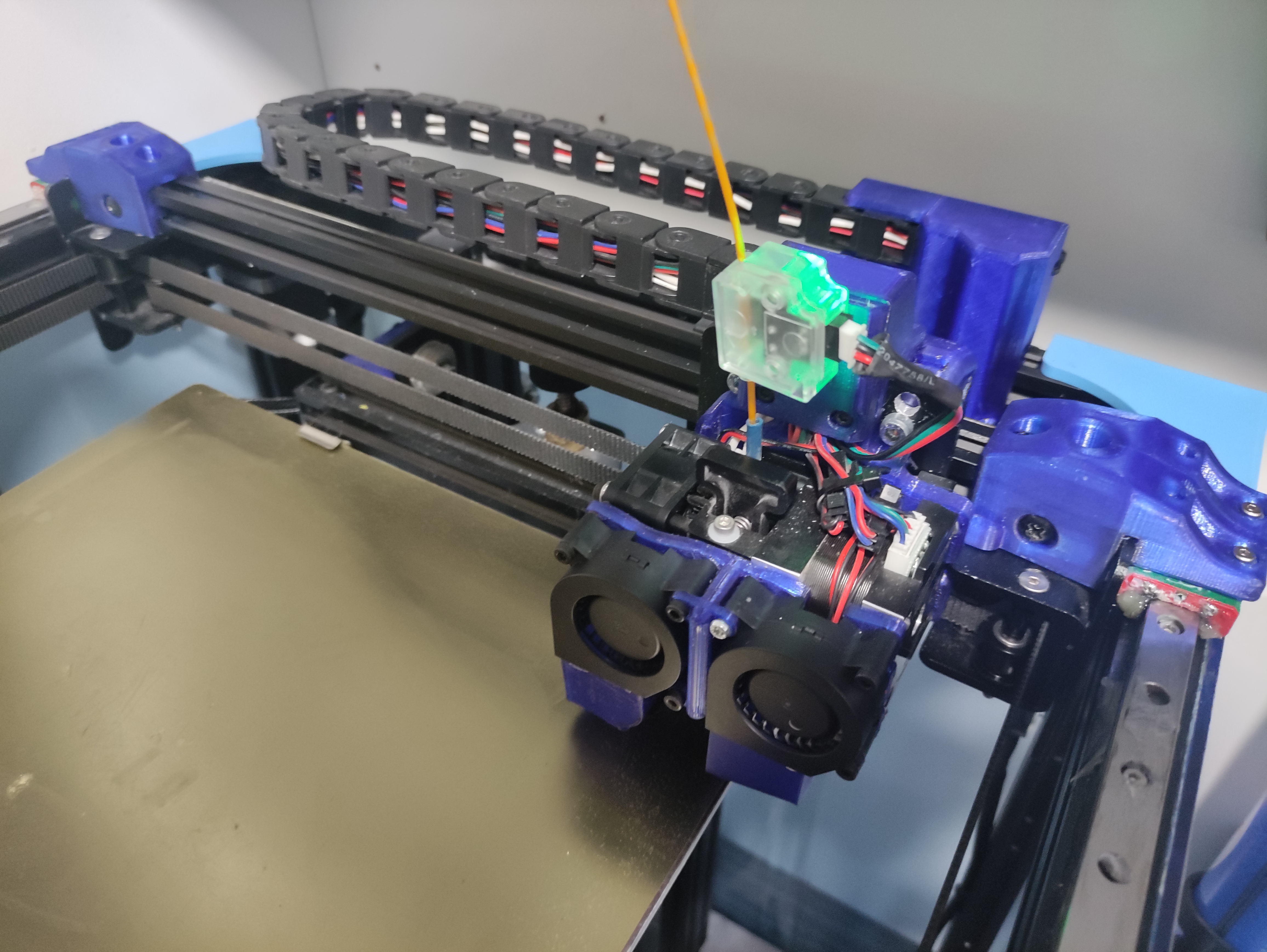
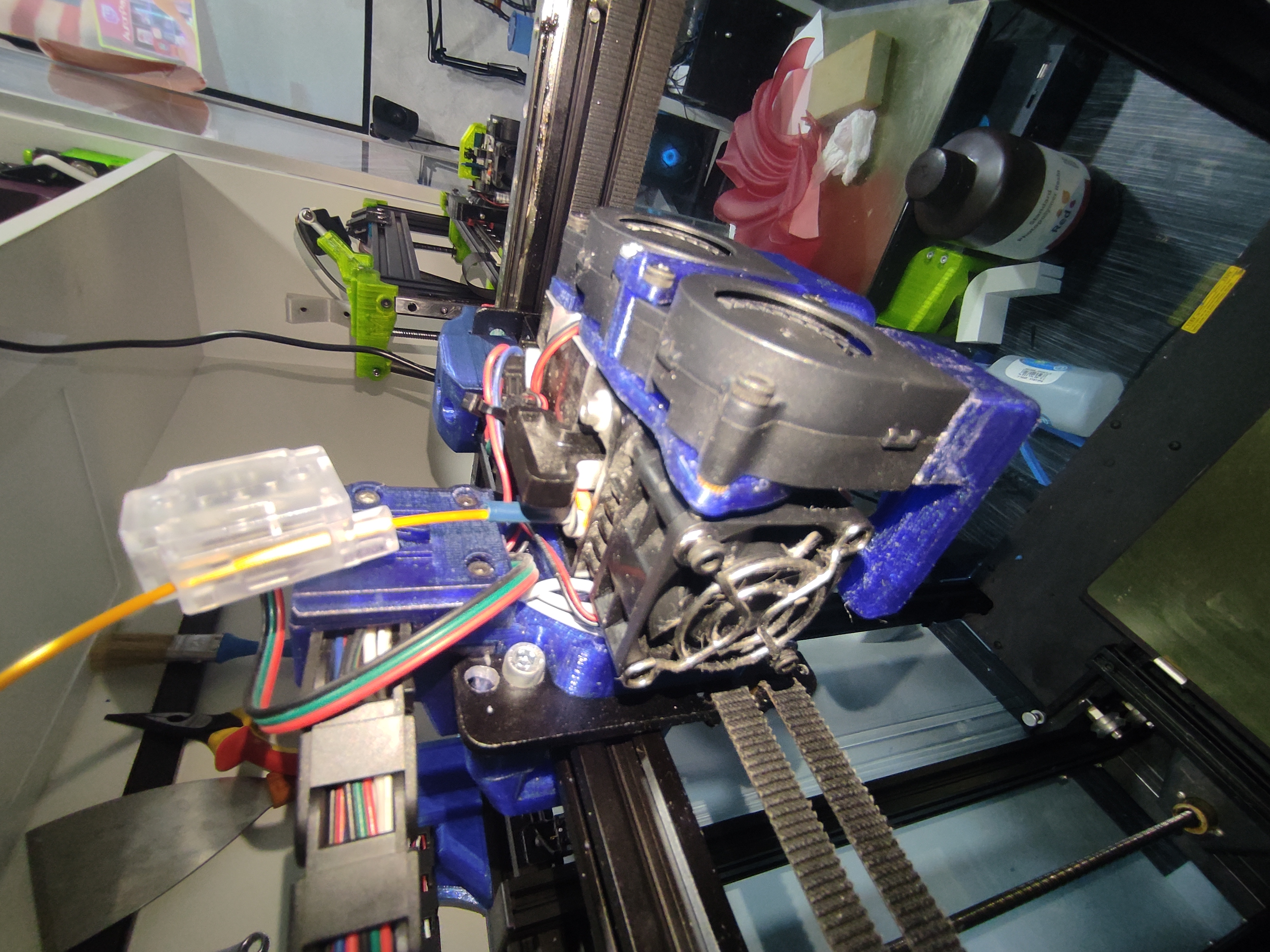
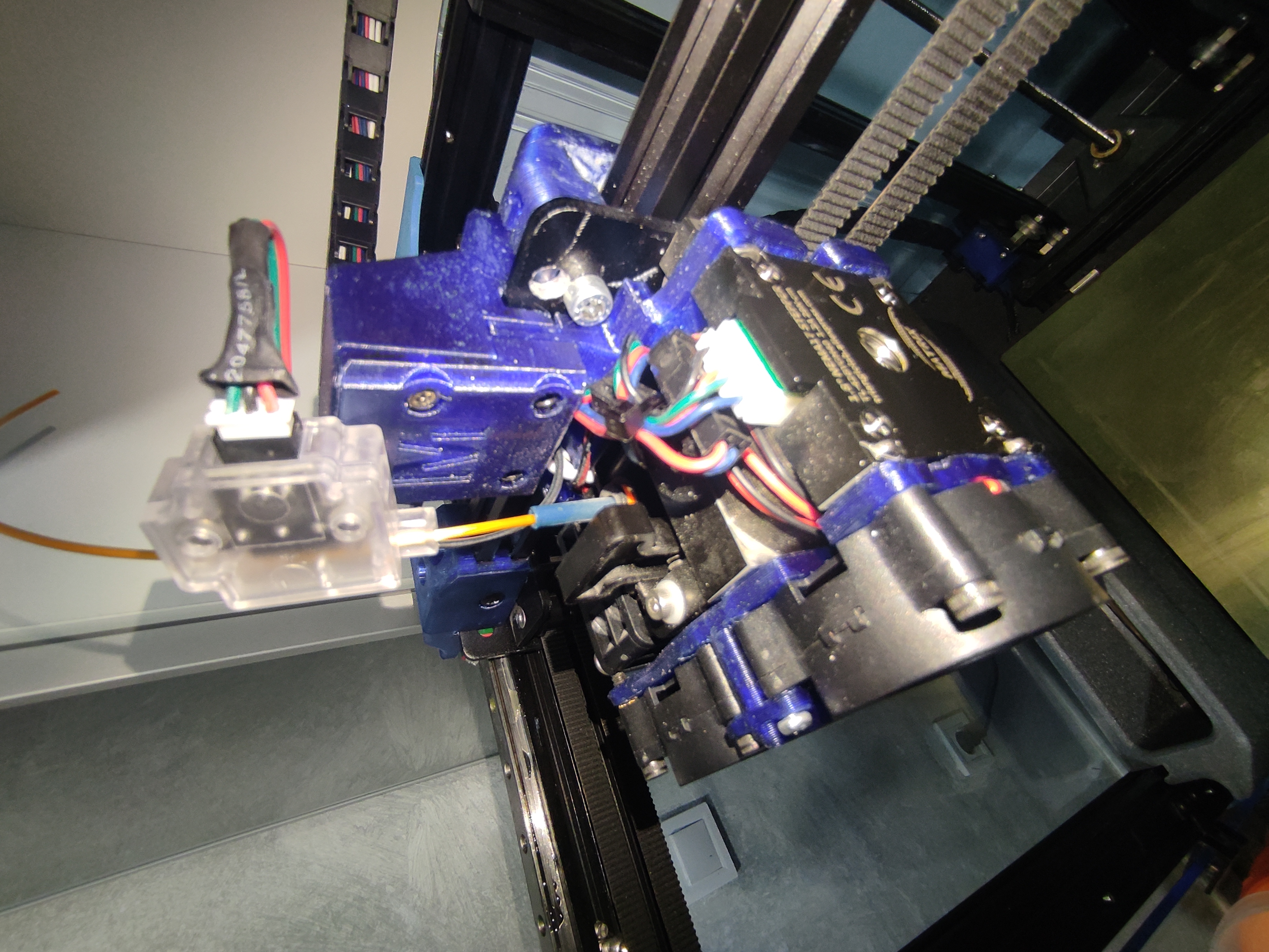
With this file you will be able to install a Hemera/matrix, Normal or Volcano extruder in your Ender 6, with a very effective, resistant and stable result.
Installation is simple, you have to have a minimum of knowledge of 3d printing maintenance.
For the installation of the base you will need 1 screw (M3x8mm) and 2 screws (M3x20mm) that will support the upper cable tie plus the base.
To support the extruder motor you will need 4 screws (M3x6mm) with the square nuts that come with the extruders themselves.
For the 4020 layer fan you will need 3 screws (m3x18mm) and glue to glue the duct to the fan.
For the relocation of the limit switch sensor you will need 2 screws (M3x6mm) and two T-M3 nuts. This is necessary to get the new center of the bed and avoid frontal collision.
and for safety and to avoid frontal collisions you can install 2 front stops with 2 screws (M5x12mm) and 2 nuts in T-M5.
other sizes are ok if you don't have M5 but the bigger the better.
IMPORTANT: it is recommended to print everything in PETG with a minimum of 8 perimeters, a layer height not too high in order not to lose definition and a filling high enough to be able to make pressure with the screws without breaking the perimeters and to avoid malformations with the temperature if the printer is closed or if technical materials are used.
INSTALLATION MODE
1.Disassemble the entire original Creality extruder and only leave the wires coming from the tube.
Separate the motor from the extruder leaving the motor on one side and the heatsink and gears on the other side.
Screw the motor to the printed base, either Normal or Volcano, using the 4 M3x6mm screws and the square nuts from the kit.
4.Screw the base with the motor to the original metal plate (in principle you can only screw the left screw, the motor blocks the right one depending on the type of screw you use) leave it as level as possible.
5.Then mount the heatsink and gears with the hotend that you want Normal or volcano with the probes already inserted,(usually come in the kits a capsule for the original probe)
Mount the fan of the original heatsink or one that you want by passing all the cables through the back, through the channel that has the base.
Remember to insert a wire for the 4 wire nema motor usually comes in the pack if you don't need at least 90cm, and insert the wires for the 4020 fan or cut and splice the original ones.
If you want to place the filament sensor as close as possible to the extruder, remember to insert a longer cable.
9.install the 4020 layer fan with the 3 M3x18mm screws and attach the vent duct according to the model chosen. if you opt for the 4020 double fan version you will also need 3 additional M3x18 screws in addition to printing the extra part.
10.Attach the top piece that holds the cable tube with 2 M3x20 screws to hold the tube and the platform to the carriage (if the screws are long they can be annoying from behind).
11.You will have to move the end of stroke sensor as far back as possible with 2 M3x6mm screws and two T-M3 nuts and you can move it to the start of the bed.
12.(optional) Fit the two front screws with T-nuts to avoid collision with the straps.
13.It is possible that the extruder wires are reversed, simply change the wires at the connector ends (reverse them).
14.You have to put in the start GCODE of the laminator under the line G92 E0
M92 E330
to change extruder pitches (Matrix and Hemera usually have 330)
They can also be changed and saved in the EEPROM of the SD card using Pronterface or Repetier Host for example
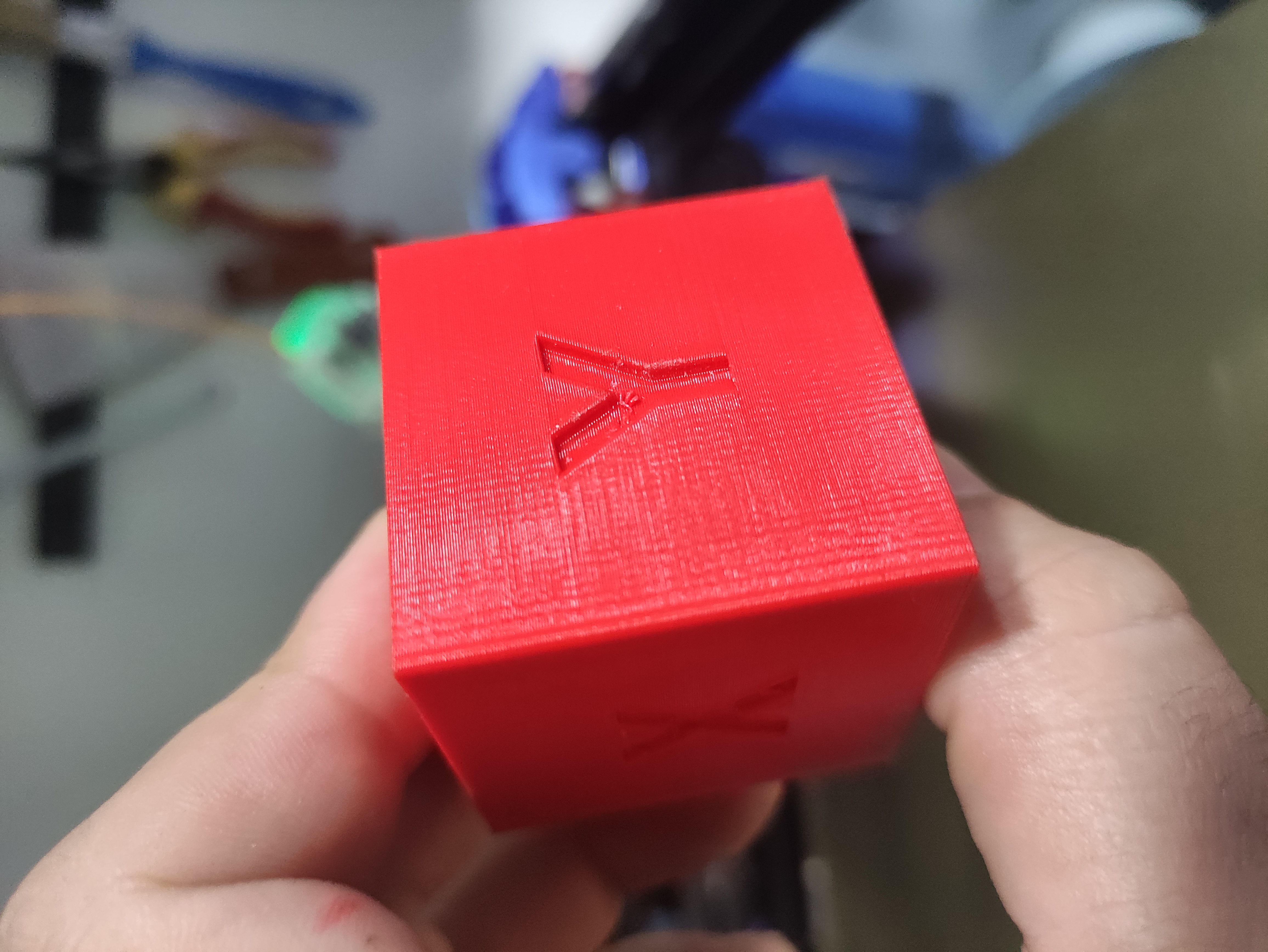
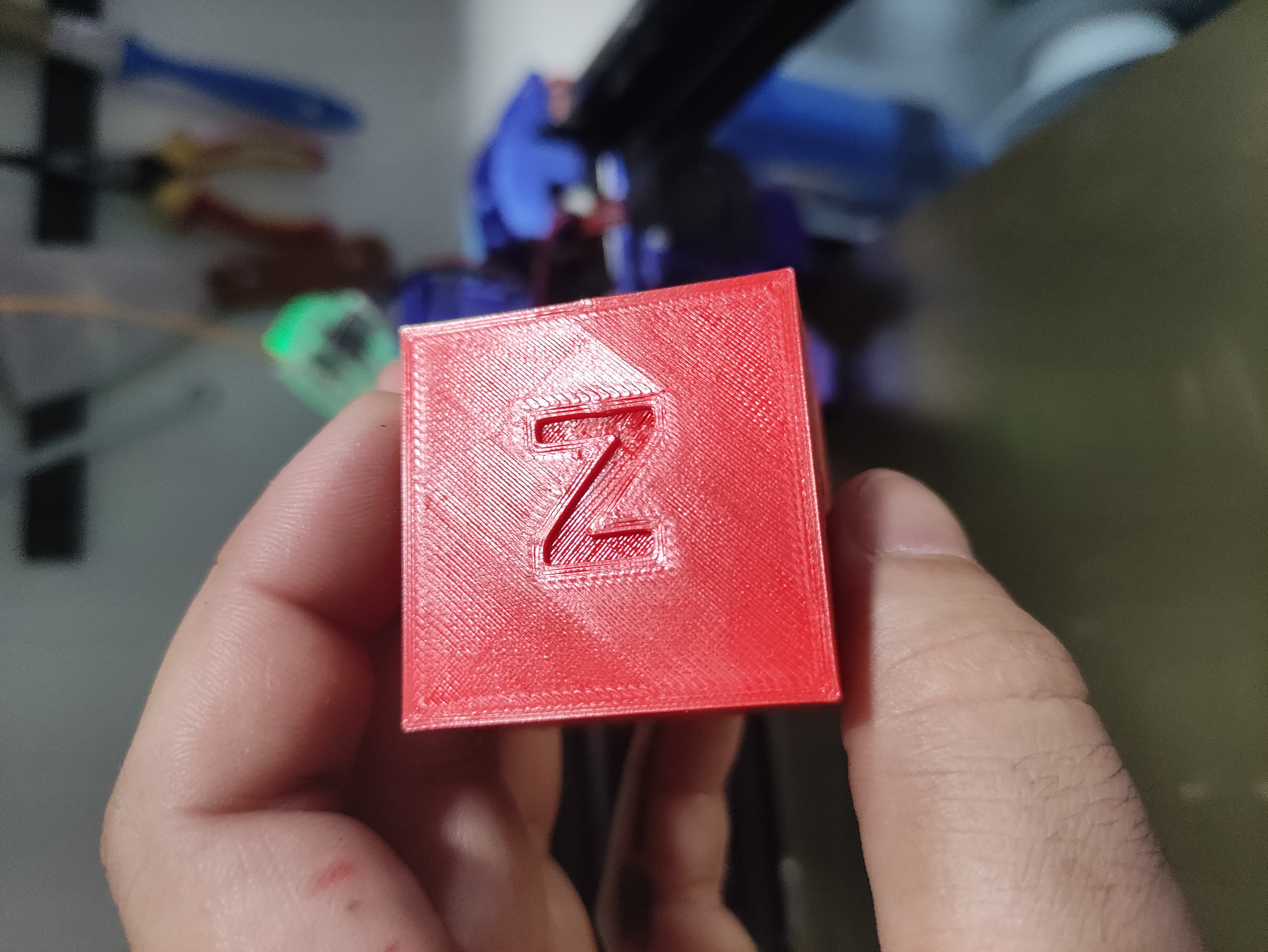
15.The size of the bed you have to measure how much your axes move, X and Y will depend on screws and stops that you use. In principle I have been able to print in measures of 26.5x26.5 the standard is 25x25 and to taste of each user.
16.For the installation of the ducts for the 4020 fan you have to download it from the following links (https://www.myminifactory.com/object/3d-print-e3d-hemera-artillery-sidewinder-x1-mount-106053) you only need the Normal or Volcano ducts. and thank the creator for his work.
For the installation of the 5015 fan you have to download the following link (https://www.thingiverse.com/thing:4042492) is a great design that also deserves your liking. I add a modified file to be able to install the 5015 in Normal or Volcano.
18.To install the dual fan you need the included modified ducting.
19.These are some works already tested and working, but it is possible that they could have some error so I would accept your comments and I would modify it without problems.
20.I recommend changing a number of accessories to improve quality and performance but they are not necessary.
Thermistor NTC 100K ohm B3950:
https://ali.ski/N2kQnx
Brass heating block
https://ali.ski/UyXPM
Heating block platedcopper:
https://ali.ski/FSx39
60W cartridge:
https://ali.ski/yYnup
Heater block heater:
https://ali.ski/roaaf_
Nozzle v6:
https://ali.ski/Kb_cd
Matrix bimetallic barrels:
https://ali.ski/yi3TRQ
very quiet 4040 fans:
https://ali.ski/_gGqOk
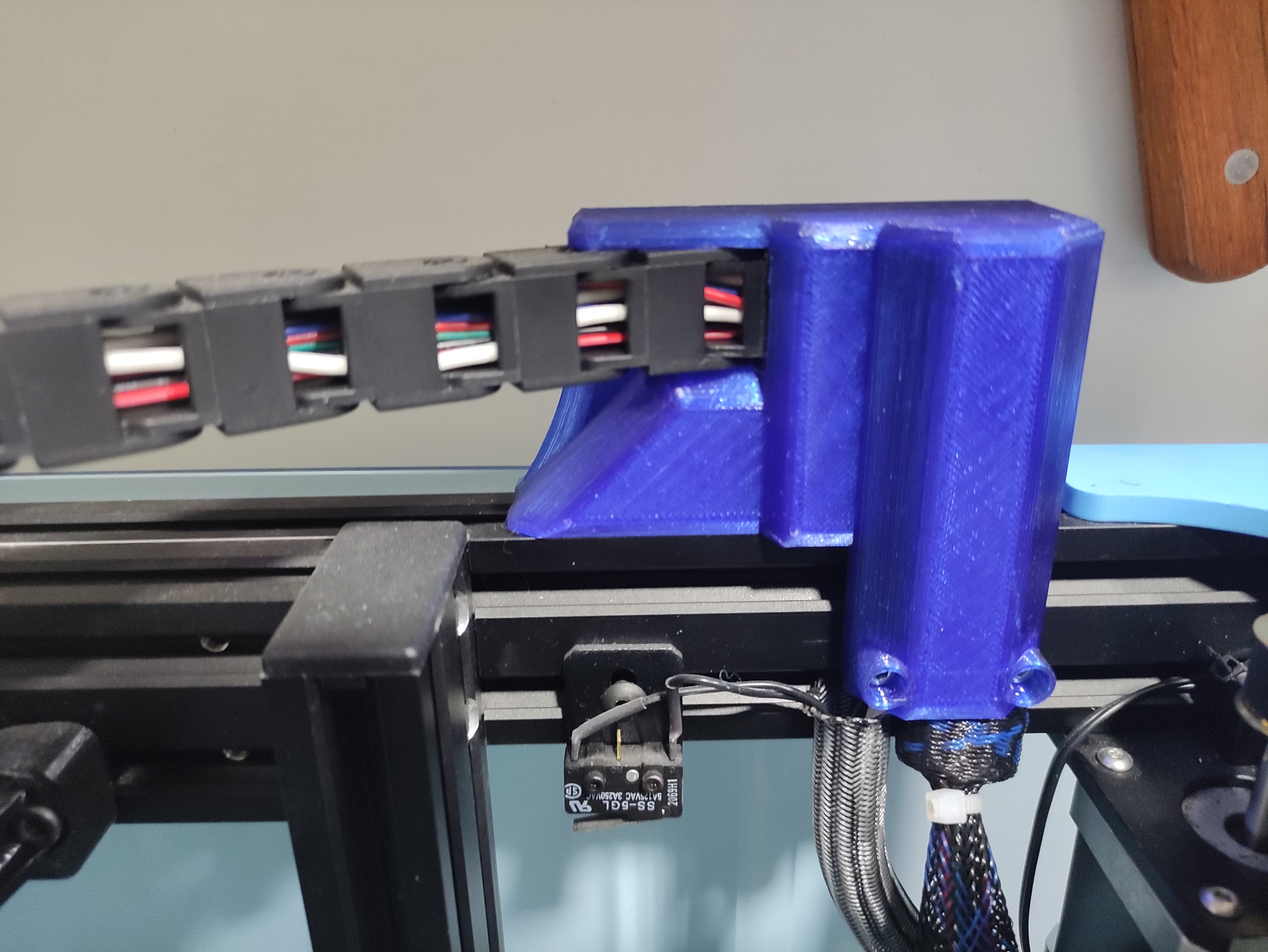
CABLE DUCT
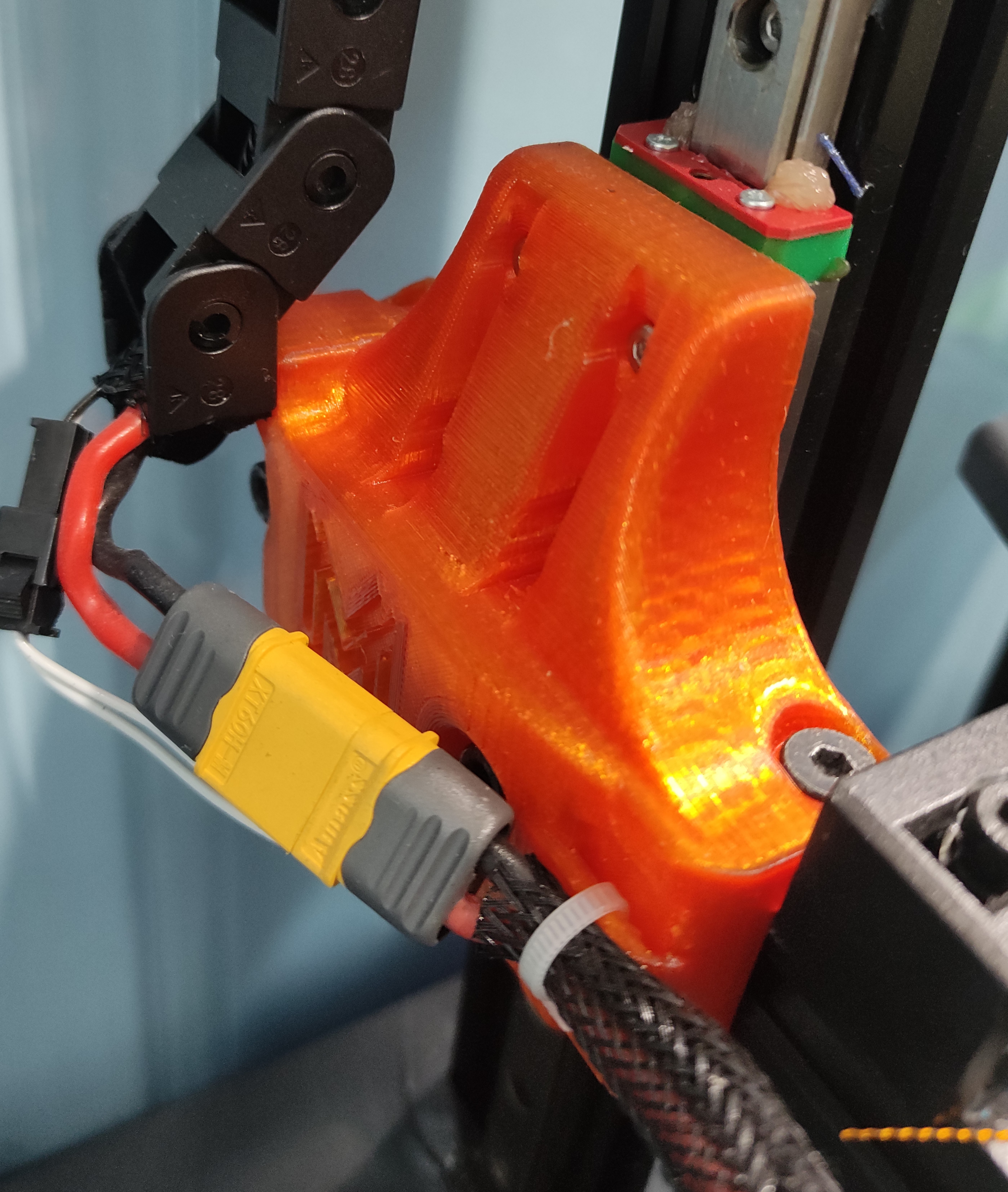
With this mod you will be able to put a cable chain for Ender 6 if you have a Matrix or Hemera engine installed with my own mod (https://cults3d.com/en/3d-model/tool/matrix-hemera-ender-6-mune1) if you already have the indicated model printed you will simply have to print the pieces of this kit and buy a 1000 mm Cable chain (10x10 mm, R28)
This is an easy process but you will have to be patient as it is somewhat slow and painstaking as the cables fit just right.
Print the kit mods
3.Put all the wires inside the conduit, if possible disassemble everything and leave them inside already to simply install.
- Fit the rear bracket, you will need T-M3 nuts, M3 screws to anchor it to the profile, and some flange, you will have to put all the cables already tucked into the trough, previously anchoring the first link to the piece with M3 screws and nuts.
4.About 60cm of trunking is used.
5.Repeat the process at the front, placing everything and leaving the wires well placed, taking advantage of bringing the wires further back towards the plate.
6.Place the front cover which also acts as a cover flange.
7.Check if you have left the gutter long or short.
- If everything is OK connect everything and test, it should run very smoothly.
9.OPTIONAL it is recommended to weld knurled nuts in order not to wear the thread, although it is not necessary.
10.OPTIONAL it is recommended to fit JTS terminals.
for quick connection of fans
11.The models shown in the photos are versions for linear guides and versions without updating, the models included are tested and working, any doubt connect with me and I would modify without problems.
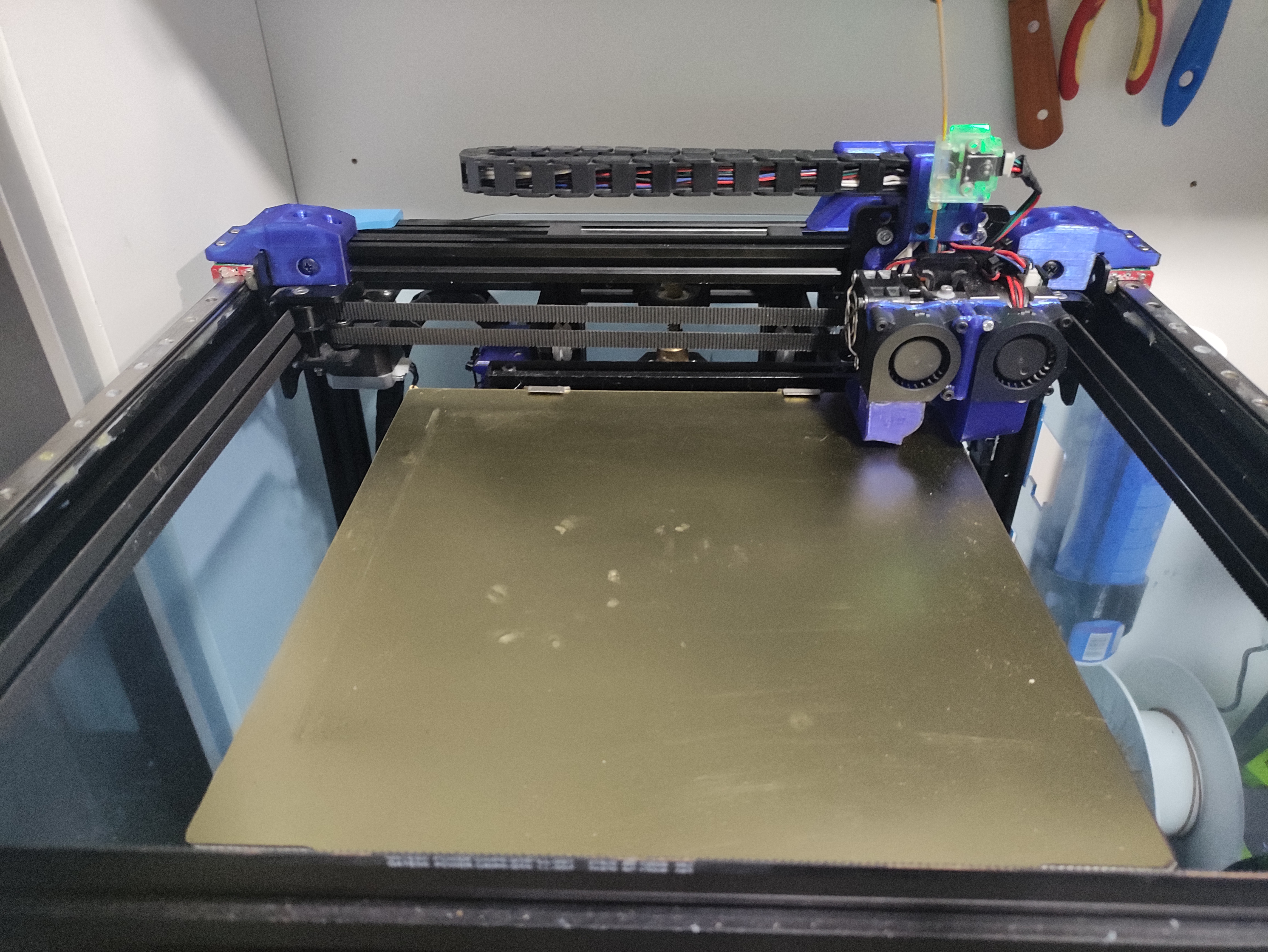
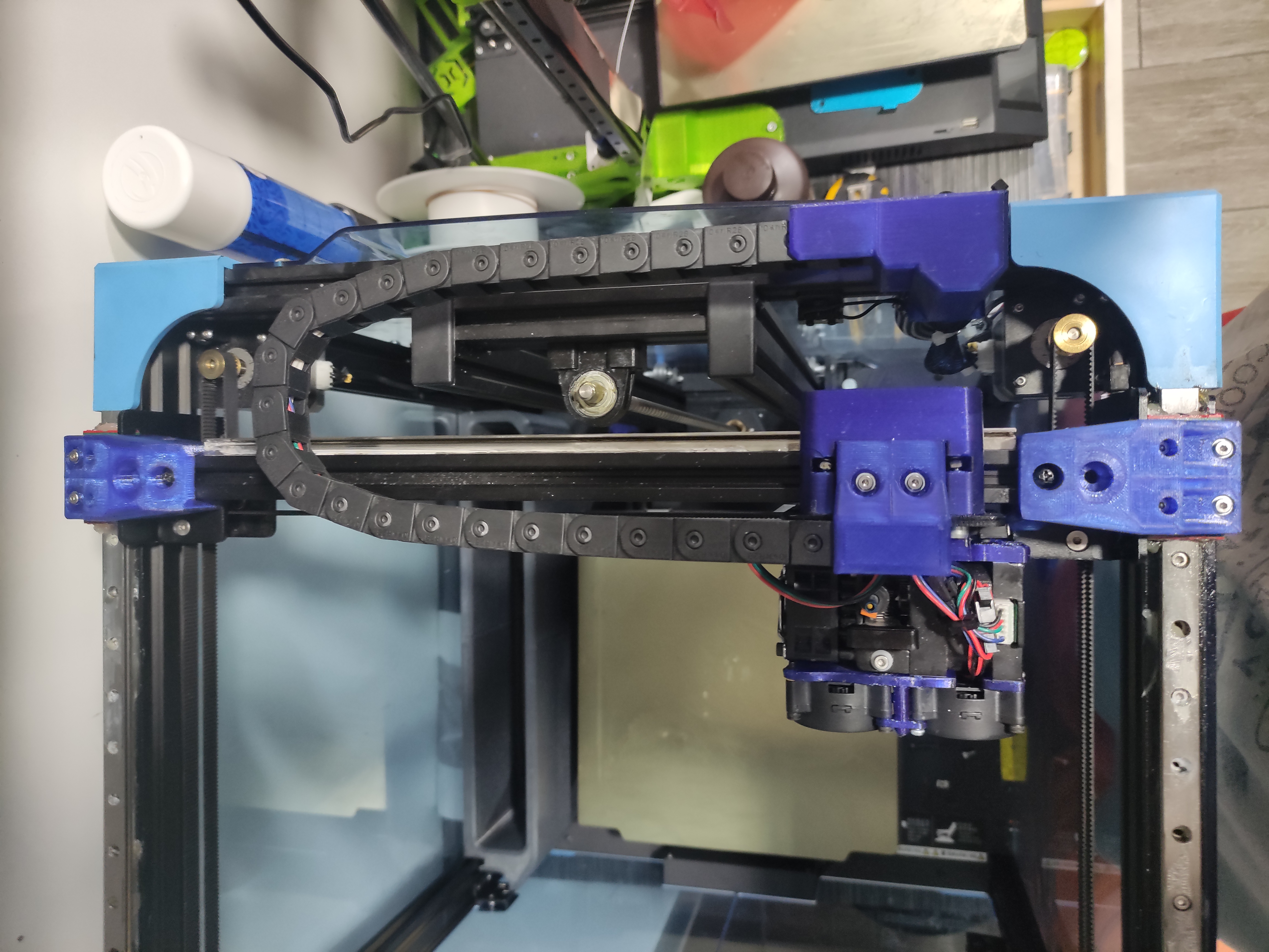
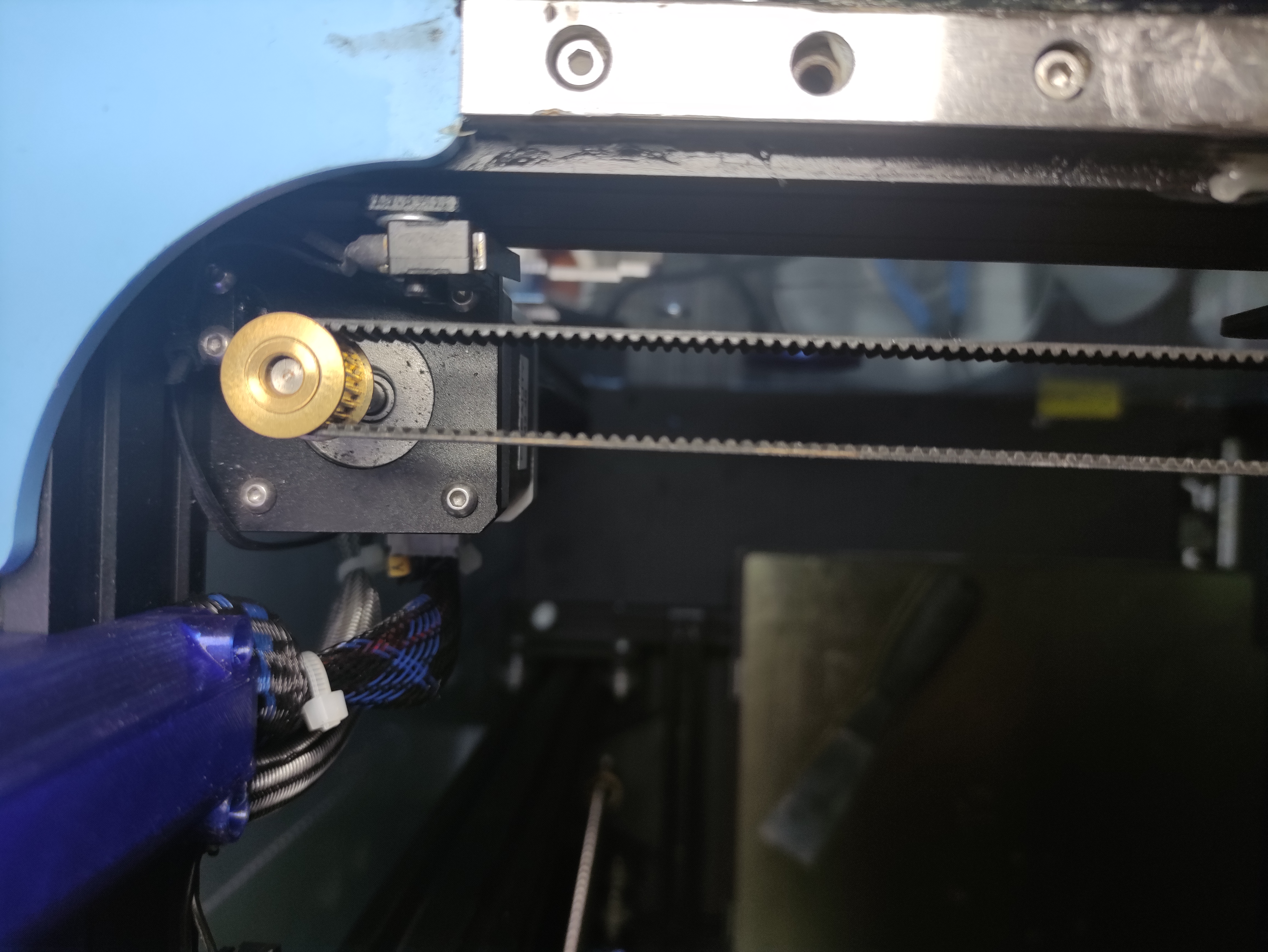
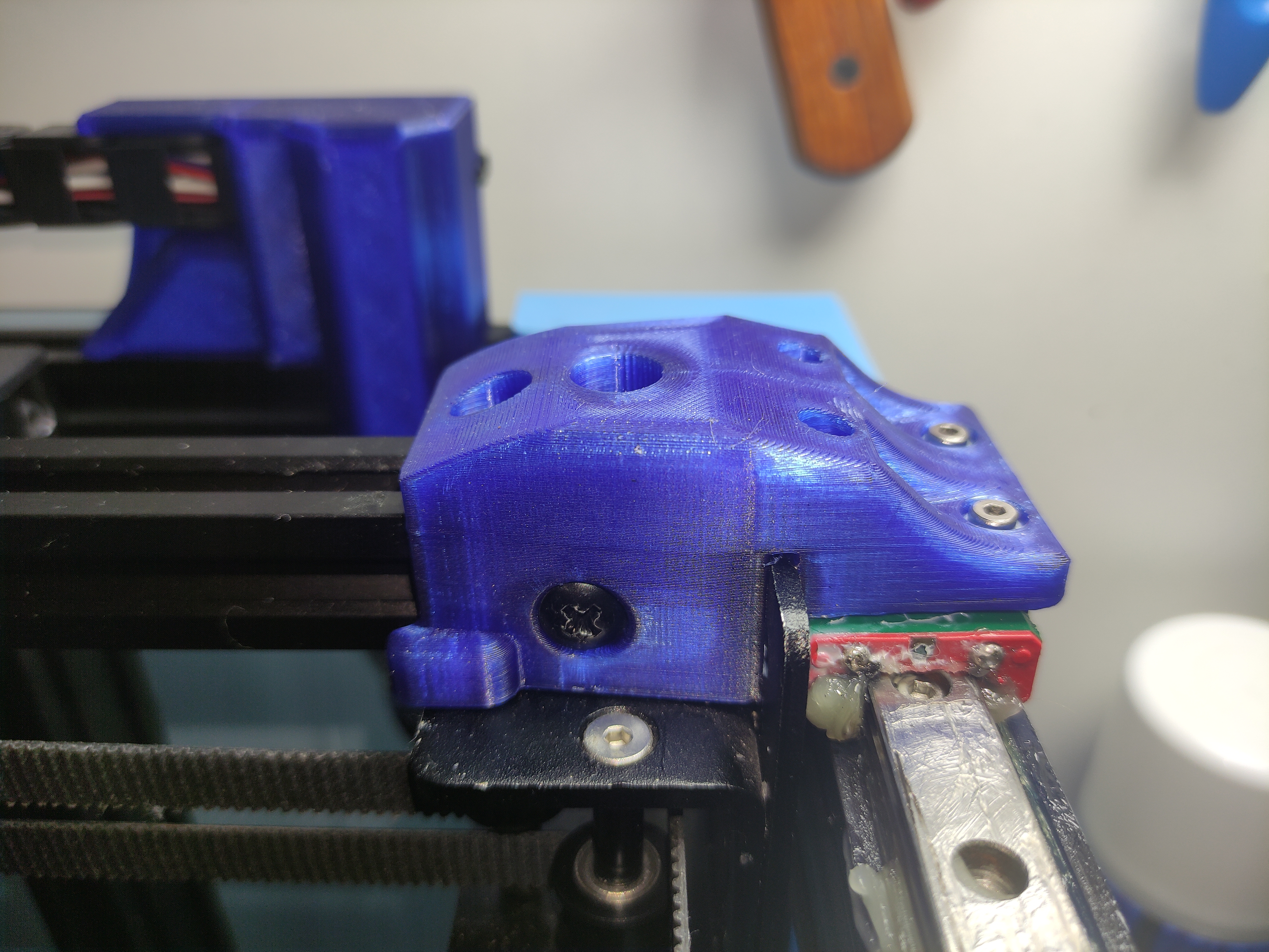
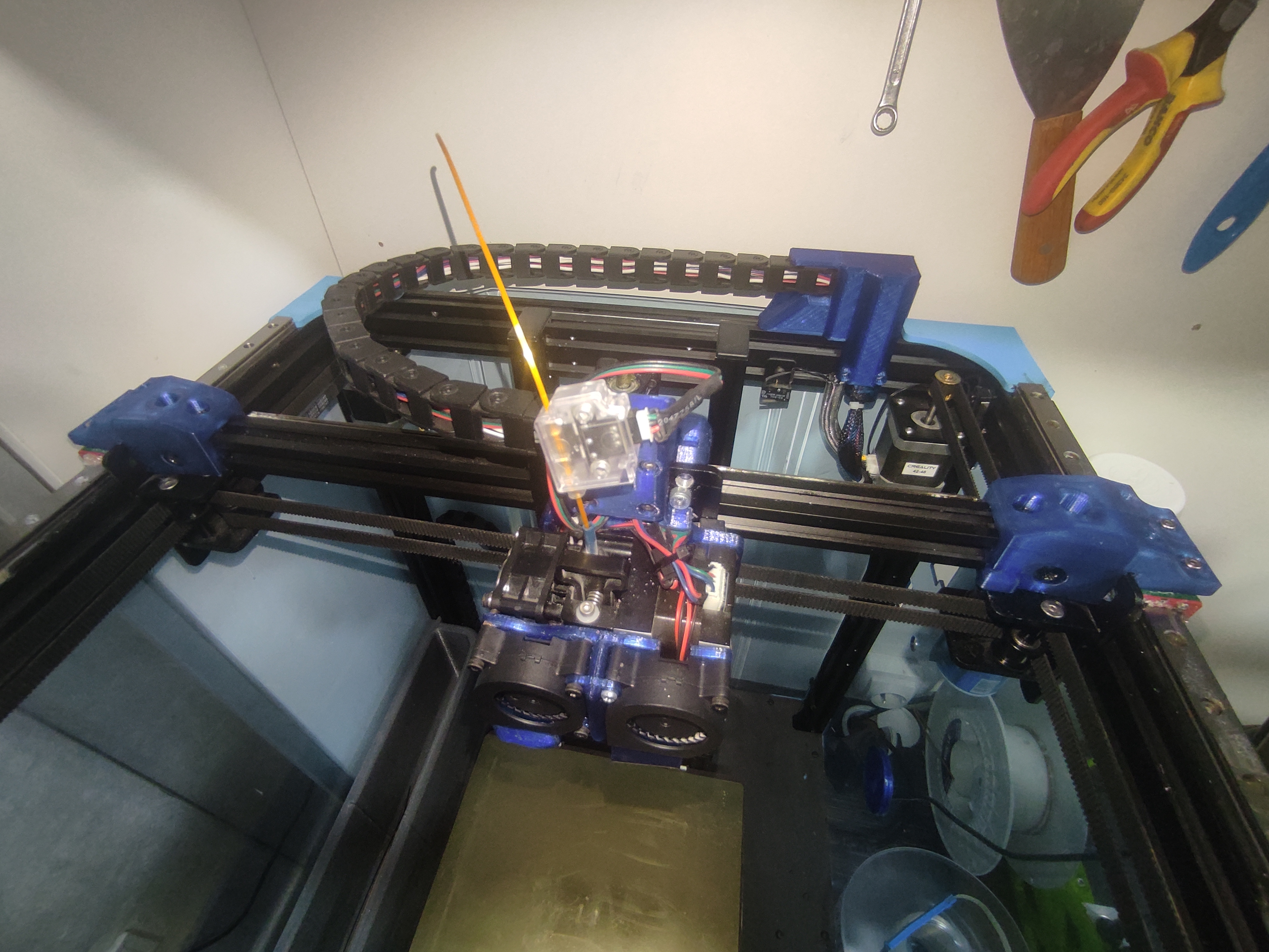
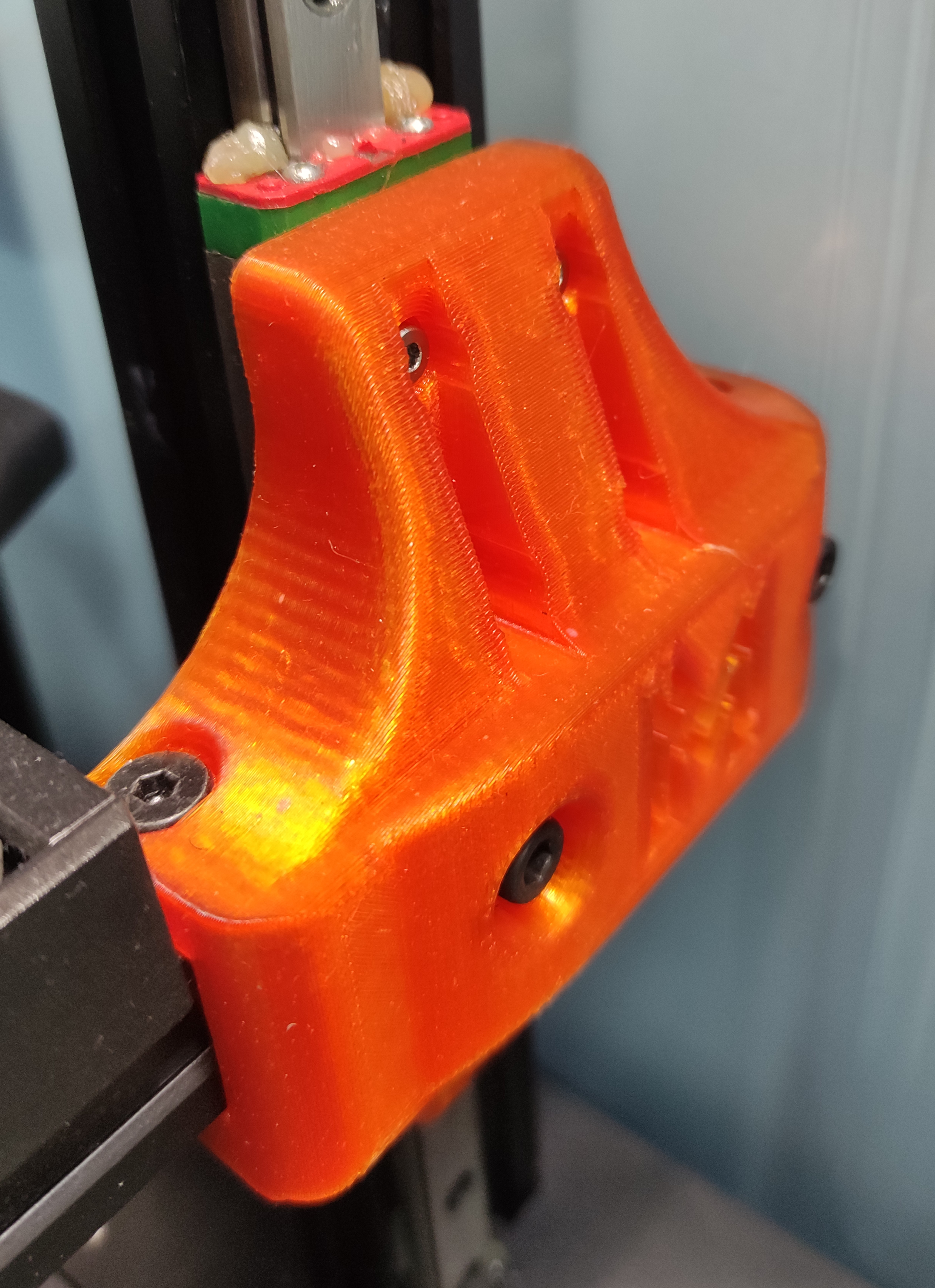
X-Y LINEAR GUIDES
With these designs you can install linear guides in X and Y axes.
the main idea of these guides I have been inspired by other public models but solving errors and improving them as well as adapting them to my previous models being a pack
The installation of these mods are not complicated but we will need some tips and materials.
We will need:
3 linear slides 350mm and MGN12H
https://ali.ski/KqcfU
M3x8mm screws and T-M3 sockets to anchor the linear guide and runners.
4 screws M4x30mm
4 screws M4x8mm or 10mm and 4 nuts T-M4
4 M5 screws minimum 22mm maximum 24mm
4 nuts M5
optional: knurled nuts M5
optional: M3 nuts
1.Print the mod with very strong PETG parameters,10 perimeters,60%-80% filling
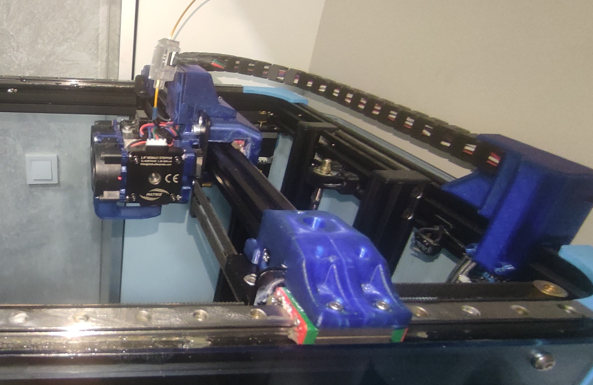
2.Y axis, disassemble the side wheels and the X profile, insert the Y axis parts taking into account that the part acting on the limit switch goes to the right, put two M4x8mm or 10mm screws with T-M4 nuts on the sides of the part and insert the 20x20 profile. Insert the upper M4x30mm screws and anchor them to the pulley supports.
3.Place the linear guides on Y axes with the runners with at least one screw every two holes and leave them fixed but not tightened.
4.Attach the printed brackets already installed on the X-axis to the runners with M3x8mm screws, but do not tighten them completely.
Tighten the screws of the linear guides checking that they are not twisted using a caliper or simply if you are an expert checking the guide of the slide.
Tighten the screws of the slides, make sure they stay tight by tightening them crosswise, but do not tighten them too much as this deforms the slide and slows it down.
If everything goes smoothly, repeat the X-axis guide step.
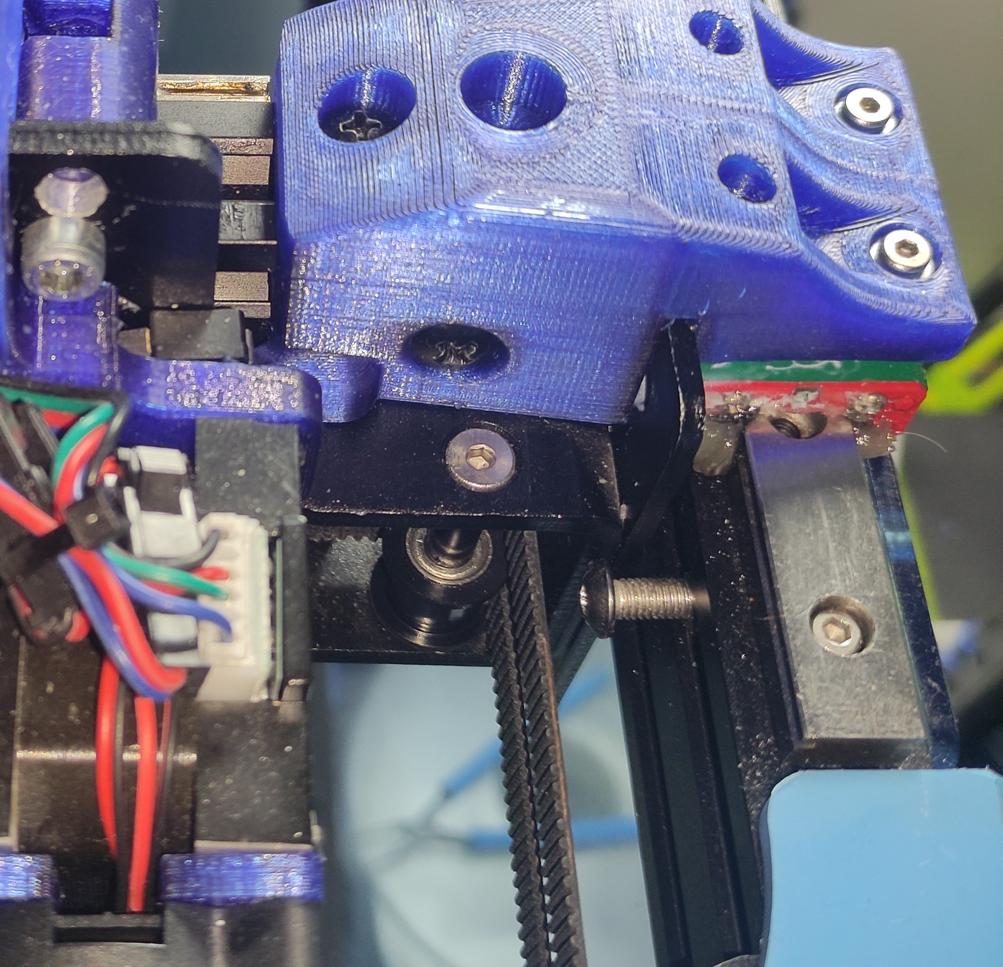
For the X axis we will have to remove the original screws and wheels and replace them with M5 screws, which will anchor the printed piece with M5 nuts that we will insert through the slots which are indicated in the mod and we will anchor it to the original base.
8.Screw the linear guide as level as possible and screw the skate as in the previous skates.
9.If you have my other mods you can install a reinforced bracket for the cable channel, which will tie all the pieces together more.
Lubricate the guides well with lithium grease and check that they don't rub, and you're done.
11.Check the tension of the belts.
11.OPTIONAL insert M5 knurled nuts for better grip on the X-axis linear mod.
:format(webp)/https://fbi.cults3d.com/uploaders/14331862/illustration-file/f2613d43-d285-49e0-b694-ad074c5e0014/IMG_20210916_222701.jpg)


/https://preview3d-images.cults3d.com/vp1xvy0e0jaxcmm5lfb1zyzaa9oe)
/https://preview3d-images.cults3d.com/aac1hwdff0zg3oobntf6w4cndnsr)
/https://preview3d-images.cults3d.com/variants/76537oz4r82vwsrsapxq0pf7y6m0/cbbb7afd8a0ec9560f7f7940881f98c31dcb04582a03efcc135070de65821be8)
/https://preview3d-images.cults3d.com/variants/g3tfh9oq44yjkufqbgcbot5g3ik1/cbbb7afd8a0ec9560f7f7940881f98c31dcb04582a03efcc135070de65821be8)
/https://preview3d-images.cults3d.com/variants/m35229uq6czq6gsvji2e4v6l895j/cbbb7afd8a0ec9560f7f7940881f98c31dcb04582a03efcc135070de65821be8)
/https://preview3d-images.cults3d.com/variants/fuh1f77a83pu40uqwkwfx3ecy5kl/cbbb7afd8a0ec9560f7f7940881f98c31dcb04582a03efcc135070de65821be8)
/https://preview3d-images.cults3d.com/variants/xxjthrtncehbe42dyricc514ah7i/cbbb7afd8a0ec9560f7f7940881f98c31dcb04582a03efcc135070de65821be8)
/https://preview3d-images.cults3d.com/variants/5mna39g18go9w7o08109p1dyudsf/cbbb7afd8a0ec9560f7f7940881f98c31dcb04582a03efcc135070de65821be8)
/https://preview3d-images.cults3d.com/variants/s56vssa582fhbzuz1txrqmvvhw07/cbbb7afd8a0ec9560f7f7940881f98c31dcb04582a03efcc135070de65821be8)
/https://preview3d-images.cults3d.com/variants/tm8vtsi8q5yx7nu54e34nuwby0m4/cbbb7afd8a0ec9560f7f7940881f98c31dcb04582a03efcc135070de65821be8)
/https://preview3d-images.cults3d.com/variants/lk53lc7v8rsvrkmaufncugggglwy/cbbb7afd8a0ec9560f7f7940881f98c31dcb04582a03efcc135070de65821be8)
/https://preview3d-images.cults3d.com/variants/utjokwf88smyvhkanekch7jqa177/cbbb7afd8a0ec9560f7f7940881f98c31dcb04582a03efcc135070de65821be8)
/https://preview3d-images.cults3d.com/skrob375rgjdievvqi62c5qnw663)
/https://preview3d-images.cults3d.com/variants/8gw62zlvqlxhff3tkedgaogag49s/cbbb7afd8a0ec9560f7f7940881f98c31dcb04582a03efcc135070de65821be8)
/https://preview3d-images.cults3d.com/variants/2gax9giy36fp3wjc6459kdb6durq/cbbb7afd8a0ec9560f7f7940881f98c31dcb04582a03efcc135070de65821be8)
/https://preview3d-images.cults3d.com/variants/aqu7hlp4sjh5rsw0q3u38pwefzdp/cbbb7afd8a0ec9560f7f7940881f98c31dcb04582a03efcc135070de65821be8)
/https://preview3d-images.cults3d.com/variants/3ovn2na88k0of84njha0kl4210ea/740653c6971db8cfdca21475487b95b09ce19114e42428007af25545a7f8a383)
/https://preview3d-images.cults3d.com/p4ybh10sb2n78fxc5y4883vdoq9f)
/https://preview3d-images.cults3d.com/pkeiufc73qoq0v6musjcpt9qj6fn)
/https://preview3d-images.cults3d.com/dq2ui60ryatxrpwtr9d9rl221q9r)
/https://preview3d-images.cults3d.com/1g63q1hyekzc029w3sfc27ilys5p)


