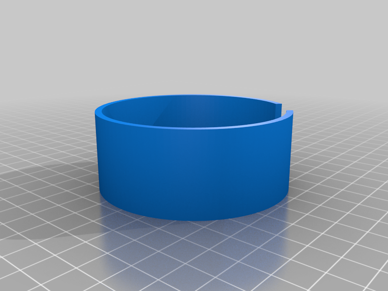
Light up cup with purple "UV" leds that only light up when someone picks up the glass.
This one fits 70mm glass cups, but I included the fusion360 file. Just change the diameter in the first sketch and right click on each body and export each body as a STL. (I used bodies instead of components to avoid model breakage in case of major size change.)
Required Parts list and where I got them:
1X 2032 battery holders: https://www.amazon.ca/gp/product/B08SQRSTJ4
1X rechargeable LIR2032: https://www.amazon.ca/gp/product/B08D8XHB23
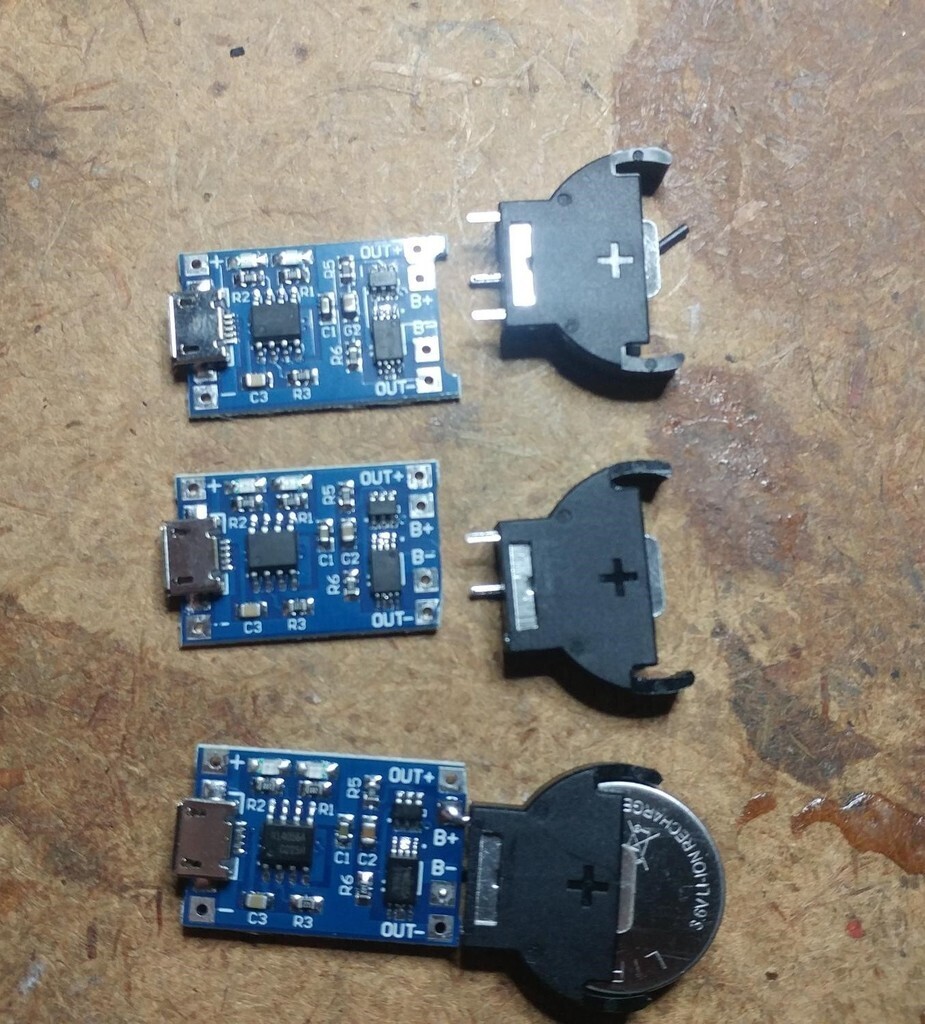
1X Battery protection board TP4056: https://www.amazon.ca/gp/product/B07KYGL71L
1X Mico switch: https://www.amazon.ca/gp/product/B07DGX9B9C
2X M3 screws: https://www.amazon.ca/gp/product/B012TBMGUE
4X 1/4w 150 ohms resistors: https://www.amazon.ca/gp/product/B07QKBRP9D
1X 1/4w 82K ohms resistors: https://www.amazon.ca/gp/product/B07HDFXLWH
4X Purple "UV" LED: https://www.amazon.com/gp/product/B077XCWMBN
22ga. Connecting wire: https://www.amazon.ca/gp/product/B075M28S6T
double sided foam tape: https://www.amazon.ca/gp/product/B08J2MXKD6
(LED is amazon.com because even with the exchange rate to get it to Canada it is still way cheaper than amazon.ca)
Quick Overview:
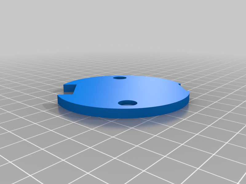
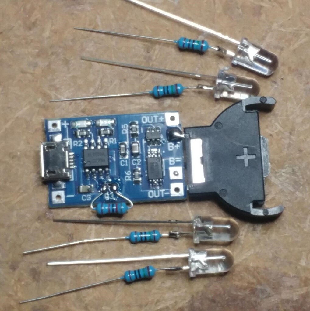
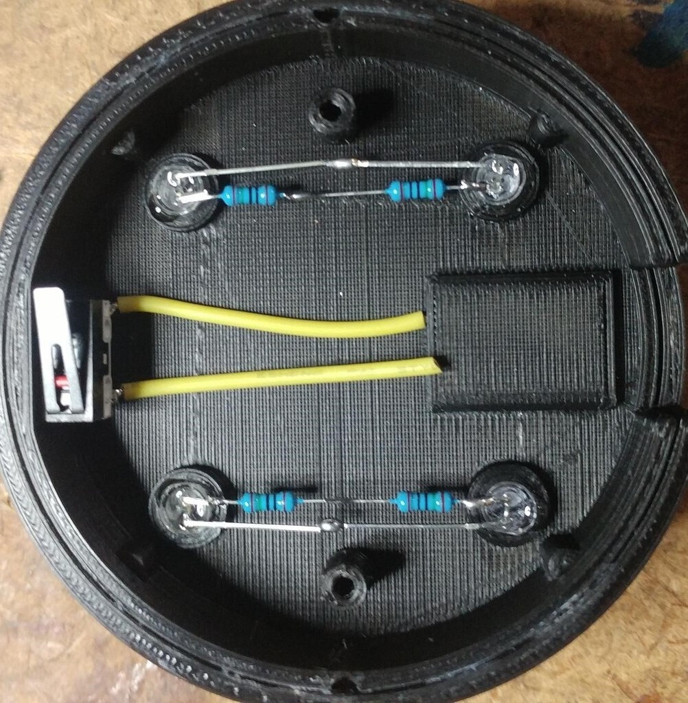
3 piece (two part glue together base + lid) housing. 150Ω current limiting resistors for each of the 4 Leds (to keep discharge current below 30mA). The charging current set resistor R3 needs to be changed to 82KΩ to set the charge current to 15mA. Switch wired into circuit through NC contacts, so it only turns on when someone picks up the glass. Stick the TP4056 board in with double sided foam tape. I recommend gluing or siliconing the leds to seal them and keep moisture from condensation out.
Long Overview:
Specs to follow:
Rough LIR2032 Battery specs:
- Max battery discharge current: 35mA
- Max battery charging current: 35mA
- recommended battery charging current: 17.5mA
- Min battery allowable voltage: 3V
- Maximum Battery allowable Voltage: 4.2V
Rough LED spec:
- Max LED current: 30mA
- recommended LED current: 15mA
In order to put LED in the bottom of a cup with a small rechargeable battery: We need to watch how much current we are pulling from the battery, how much current we are charging the battery with, the max/min voltage of the battery and the Current going through the LEDs.
The Battery I have chosen is the LIR2032, its a common size small lithium ion rechargeable Battery, the CR2032 is the same size but is not rechargeable.
To tackle the charging current and battery voltages we need a battery protection module. The Board is "TP4056 charging module" It has two separate chips that protect the battery from: wrong polarity protection, short circuit protection, disconnects the battery at 4.2V while charging, disconnects the battery at 3V while discharging and controls the charging current. The only problem with this module is that its default charging current is 1A which is set by resistor "R3." We need to change that resistor out to 82K ohms to bring the charging current down to a better 15mA for the small battery.
As for the LEDs we cannot connect them directly across a Battery without drawing too much current out of the battery and two much current through the LEDs. Normally for a full lithium Battery of 4.2V you would use a 82 ohms resistor for about 15mA going through the LED. But with 4 LEDs is parallel that would be 60mA drawing from the Battery two times the allowable maximum battery current, making that battery not last very long. So we can add either second battery in parallel (which we do not hove room for) or use a larger resistors to put less current through the LEDs. I have chosen 150 ohm resistors to solder in series with each LED, which makes about 7mA going through each LED. The LEDs will be dimer but still plenty bright enough to get the job done and it will only draw 28mA out of the Battery.
To assemble:
- glue the two base cylinders together
- The battery holder with two legs is the Positive side, cut one off
- bend then solder the battery holder legs (one on each side of the Battery Protection Board) to the Battery "B+ and B-"
- cut short the long (positive) leg of each led shorter leaving about 3/16, 5mm
- solder an 150ohms resistor to each cut short led leg
- Bend the LED legs in a way so each resistor and non resistor legs of two LEDs meet up on each side
- using connecting wire to connect each side resistor and non resistor led legs together in parallel
- using connecting wire connect the paralleled connected resistor LED legs to "out+" on the Battery Protection Board
- using connecting wire connect the paralleled connected non resistor LED legs to the "NC" (normally closed) terminal of the micro switch
- using connecting wire connect the "com" (common) terminal of the micro switch to the "out-" on the Battery Protection Board
- cut the "NO" terminal on the micro switch off and bend to 90 degrees inwards
- glue the micro switch to the flat section on the side of the cup base so the switch gets pressed when the cup is put down
- insert the Battery, press the micro switch to "activate" the Battery Protection Board
- use double sided foam tape to attach the Battery Protection Board on the pedestal on the underside of the cup base
- screw the cover on with M3 screws
- insert the cup, the 4 internal line grips might have to be shaved down a bit for a looser grip, DONE!
P.S. While you're at it you can solder an extra battery holder onto a Battery protection board with new charging current resistor for a USB powered LIR2032 battery charger.
P.P.S. This isn't Big Clive Dot Com's official Evilution glass, it doesn't have the BCDC on the side, I will leave the BCDC off in case Evilution wants to put his design on here
:format(webp)/https://fbi.cults3d.com/uploaders/20617403/illustration-file/a56deb91-41c6-4929-b00a-79e39971c775/cup_light_pic5.jpg)


/https://preview3d-images.cults3d.com/variants/os5ktzbisd6zfdm9fgl1lxv8labm/77d3f3b93f425080e8527932a83b54282f99f31ca9700de02f554c0ba0d78731)
/https://preview3d-images.cults3d.com/variants/muu0rf996nwlvtne01rw2zw9vjqs/77d3f3b93f425080e8527932a83b54282f99f31ca9700de02f554c0ba0d78731)
/https://preview3d-images.cults3d.com/variants/r8njwyzoakdp3q6vs2txvxxg7z6y/77d3f3b93f425080e8527932a83b54282f99f31ca9700de02f554c0ba0d78731)


