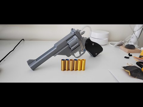
Iterating on my blowgun designs, I decided to tackle a classic mechanism: The Single Action Revolver.
This is a six shot, break action revolving cylinder gun that shoots the same 1 inch blow darts used in my Bolt Action Rifle and uses the same shells. Load six shells into the cylinder and screw in a CO2 cartridge, then pull the trigger to fire. Cocking the hammer back and releasing rotates the cylinder into the next position, readying for fire again.
This design was inspired by the Webley Revolver and has a similar form factor.
https://www.youtube.com/watch?v=BSjc8RC7HmA
DISCLAIMER: By downloading these files, you agree that I shall not be liable for any damage, injury or harm resulting directly or indirectly from the use of these files or instructions. Check your local laws and always be safe and aware when operating these mechanical toys and enjoy!
Required Parts
Rigid Tube (10mm Inner Dia, 14mm Outer Dia)
Flexible tubing (4.25mm Inner Dia, 5.75mm Outer Dia). The inner dia is less critical than the outer dia, which should be between 5.5mm and 6mm.
Mini blow darts
16g or 20g threaded CO2 canisters
CO2 Tire Inflator
M4 screws
M3 Screws
M2 Screws
7/32" x 11/16" Compression spring
Small Rubber bands
Printed Parts List
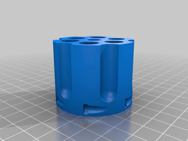
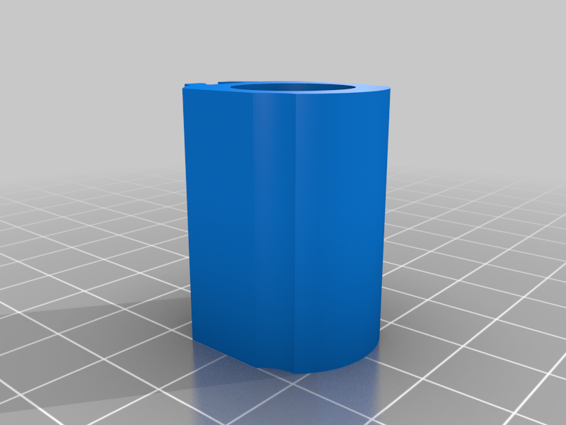
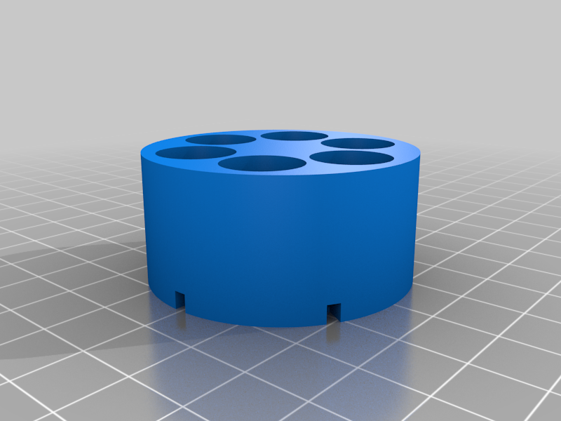
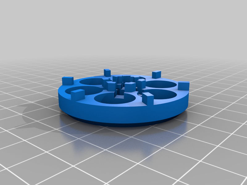
ShellCylinder
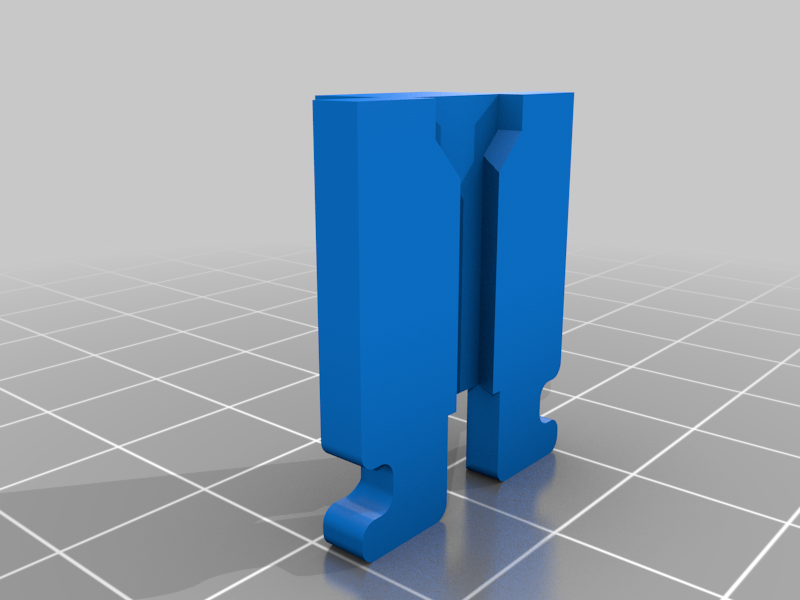
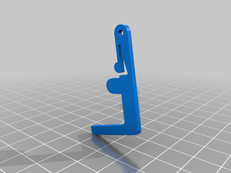
RearFrame
BarrelFrame
BarrelShroudExtender (Optional)
FrontSightBarrelShroud
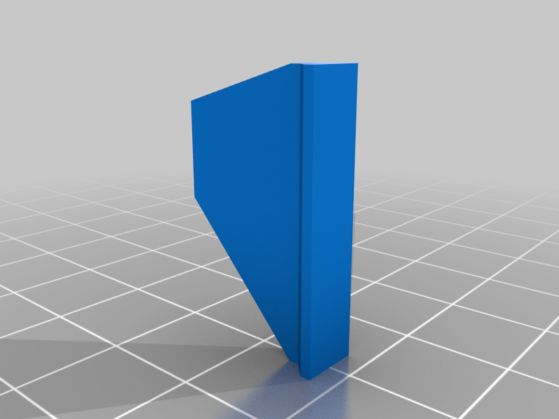
FrontSight
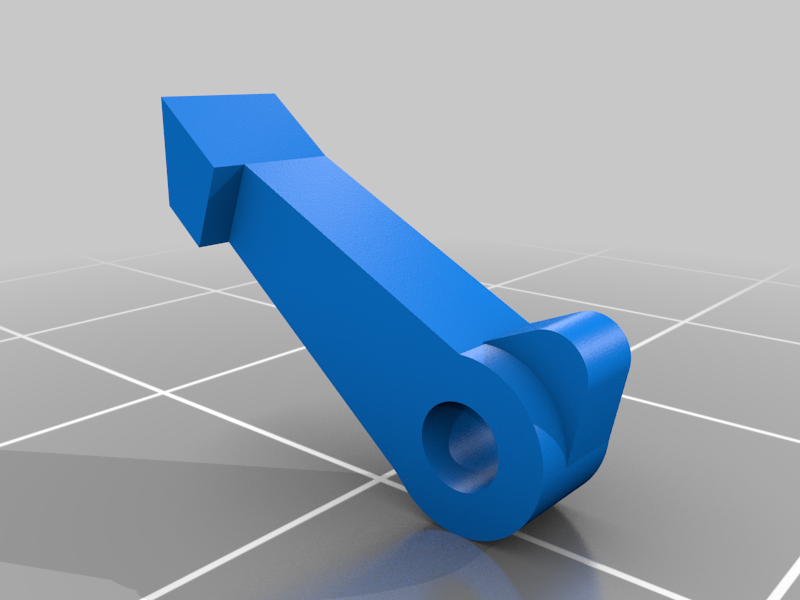
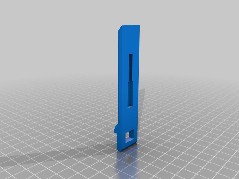
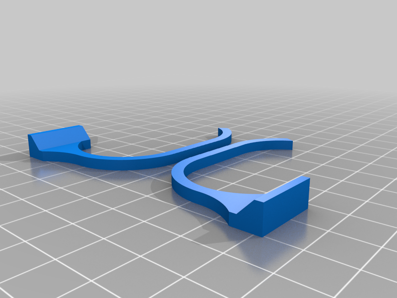
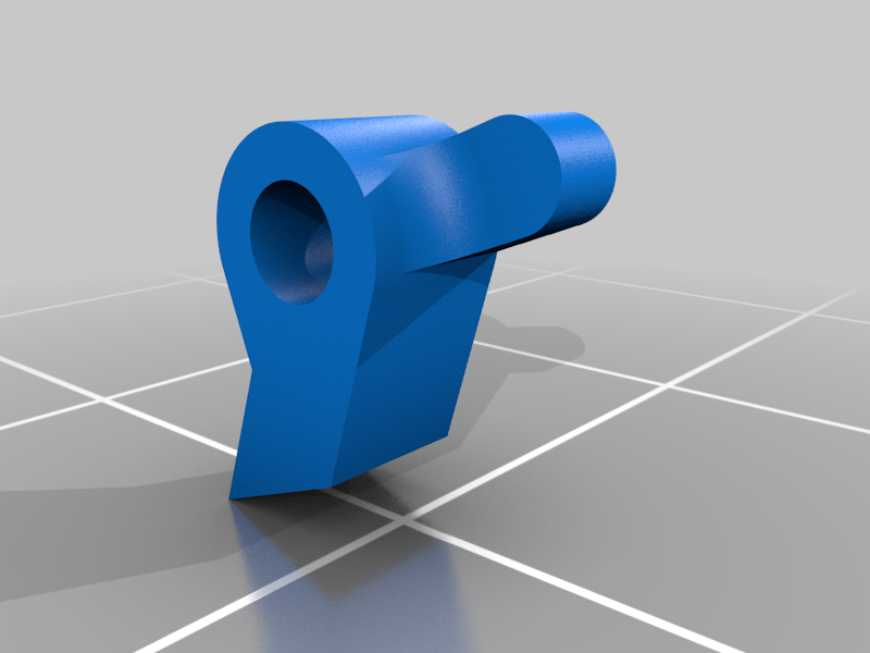
LockBar
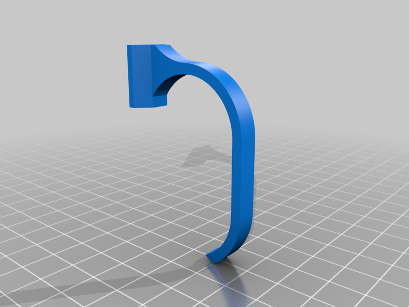
BarrelLatch
NozzleSlider
Hammer_Split
HammerPawl
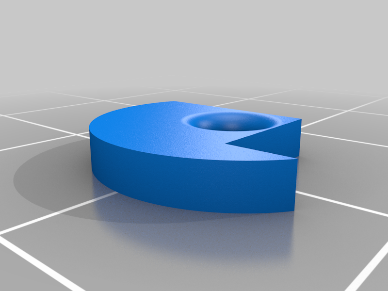
CylinderRatchet
RearFrameLockBarPlate
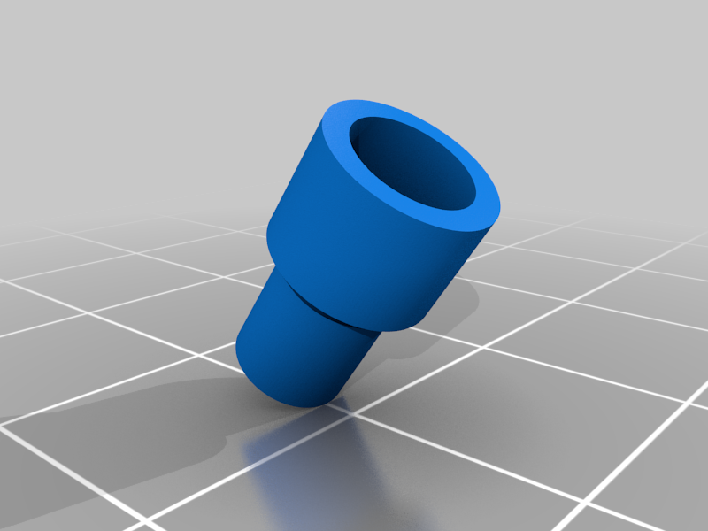
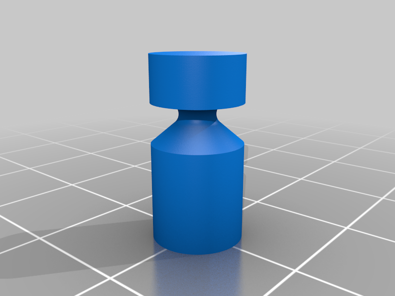
CylinderAxle
CylinderSpringPin
CylinderIndexPin
TriggerGuard_Split
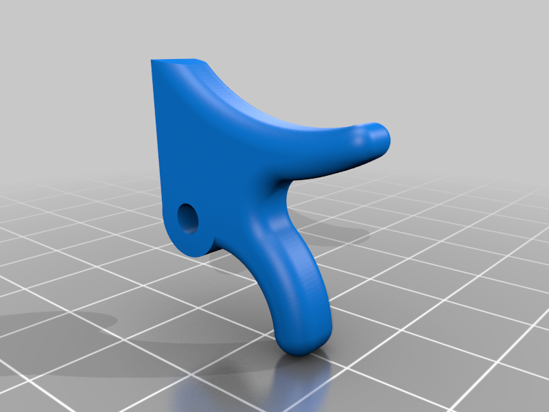
Trigger
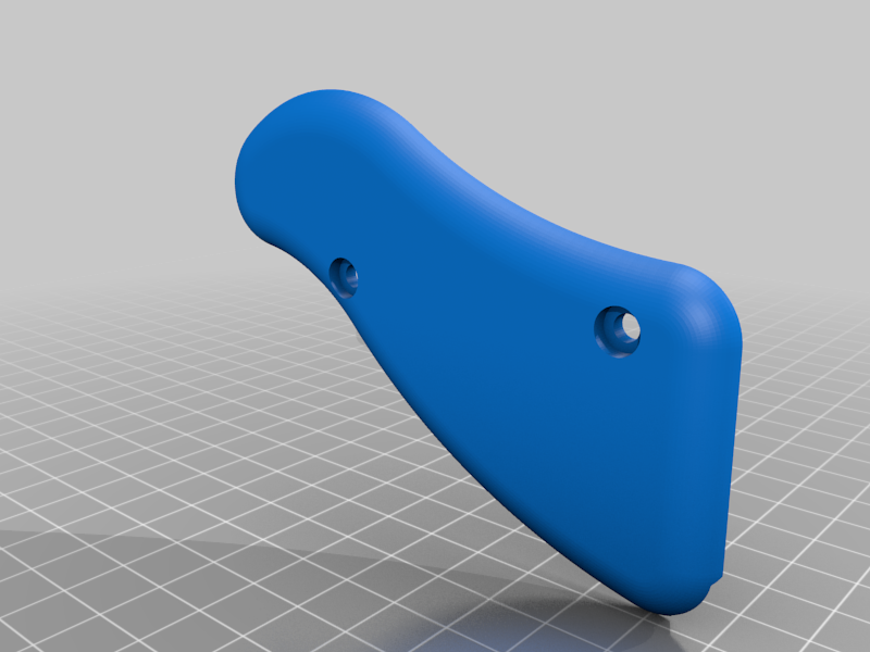
GripFrame_R
GripFrame_L
GripPlate_L
GripPlate_R
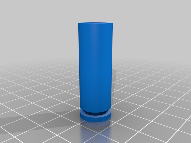
DartShell [x6]
Assembly Guide
Shell Printing
Ive included two variants of the shell depending on your printer's tolerance / filament.
One has a 10.1mm inner diameter for a tight fit with the darts, and the other has a 10.3mm inner diameter for a somewhat looser fit. The darts should be pretty tight when inserted such that they dont fall out when tipped upsidedown, but not so tight that they cant be pushed out. Try printing one of each shell to see which works best for you. You can do finer adjustments to the tolerance by putting some scotch tape or masking tape on the inside of the shell wall.
Print the shells with the flat bottom on the build plate at 0.3mm layer height. You might want to add a 2 or 3 mm brim to keep them attached to the build plate. If so, ensure you cut off the brim with a knife so there is no extra flashing as this will prevent them from being properly seated in the cylinder.
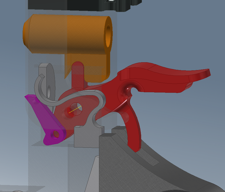
Rear Frame Assembly
Gather the following parts: RearFrame, Hammer_Split, HammerPawl, CylinderIndexPin, RearFrameCylinderLockPlate, NozzleSlider, RearFrameLockBarPlate, PawlSpring, BarrelLatch, M2x20mm screw, M2x8mm screw, M3x30mm screw, M2x6mm screw.
See the image for help with this section.
First, take the CylinderIndexPin and place it into the narrow channel on the bottom of the RearFrame. Align the hole in the front of the pin with the hole in the RearFrame and secure with the M2x20mm screw. It should be able to rotate freely around the screw, if not, sand down the pin.
Slide the RearFrameLockBarPlate onto the rail on the top of the RearFrame and glue into place.
Next, take the two halves of Hammer_Split and use some super glue to glue them together. Make sure you apply glue to the thin arc at the bottom of the hammer.
Next, take the HammerPawl and align its hole with the left side of the Hammer and use the M2x8 screw to secure it to the hammer from the right side of the hammer. It shouldnt be too tight as it must rotate around the screw.
Place the NozzleSlider into the cylindrical hole on the RearFrame, then place the Hammer and Pawl assembly into the slot, such that the tab on the top of the hammer is in the cutout on the NozzleSlider.
Place the BarrelLatch around the RearFrame and line up the larger hole with the Hammer Axis hole, then use the M3x30 screw to connect the BarrelLatch, RearFrame and Hammer together, going all the way through to the other side. You should be able to rock the hammer back and forth, which should push the NozzleSlider in and out.
Screw the M2x6 screw into the small hole on the left side of the BarrelLatch. Well use this screw later to connect a rubber band so that the latch springs back into place when closed.
Now, take the PawlSpring and apply some glue to the bottom and sides of the rectangular plate on it. Slide it in next to the left side of the hammer, behind the Pawl and hook the curved spring part around the hammer axis screw and press it into place such that the bottom of the rectangular plate is flush with the bottom of the slot on the RearFrame, and the back face of the rectangular plate is flush with the back face of the RearFrame. Let the glue dry and ensure that the hammer and pawl still rotate freely. The springs purpose is to push the pawl forward when engaging with the CylinderRatchet.
Take the RearFrameCylLockPlate and glue it into the shallow circular cutout on the front of the RearFrame, ensuring the cut side faces the pawl.
Finally, take your small rubber band and loop it around the hooks on the RearFrameLockBarPlate and stretch it around the semicircular notch on the hammer. This should allow the hammer to return after being cocked back.
Barrel Frame Assembly
Gather the Following Parts: BarrelFrame, CylinderAxle, LockBar, CylinderSpringPin, BarrelShroudExtender, FrontSight, FrontSightBarrelShroud, rigid tube, M4x20 screw and nut.
Note: The default length of the barrel tube is 130mm but you can make it longer or shorter if you want. To increase the length, just scale up the BarrelShroudExtender along its length axis. To make it shorter, you can scale down the BarrelShroudExtender or omit it entirely.
Cut your rigid tube down to 130mm. Push it through the hole in the BarrelFrame so that one end of the tube is flush with the rear of the BarrelFrame.
Slide the BarrelShroudExtender over the tube and press it onto the BarrelFrame such that the small notch lines up. You can glue it into place now if desired.
Slide the FrontSight into the rail on the FrontSightBarrelShroud. It should have a tight fit, but if not, you can glue it into place. Feel free to make your own front sight and exchange it!
Slide the FrontSightBarrelShroud over the tube and press it onto the BarrelShroudExtender such that the notches align. Again, feel free to glue it together at this point.
Next, take the LockBar and slide it onto the rail on the top of the BarrelFrame. Apply some glue and slide it all the way back.
Finally, take the CylinderAxle and place your compression spring into the hole on the axle. Place the CylinderSpringPin over the spring such that the spring is inside the small hole on the CylinderSpringPin. You can then place the CylinderAxle into the smaller hole under the barrel on the BarrelFrame and optionally glue into place.
You can now connect the Barrel assembly to the RearFrame assembly via the M4x20 screw going through the pivot on both assemblies. Secure with the nut and ensure they can rotate freely.
Cylinder Assembly
This part is nice and simple: Just take the ShellCylinder and CylinderRatchet and glue the Ratchet into the hexagonal slot on the top of the ShellCylinder. You can then place the Cylinder onto the CylinderAxle. Closing the Barrel should push the CylinderSpringPin back until fully closed, where the SpringPin should snap into the hole on the RearFrame's CylinderLockPlate. Meanwhile, the BarrelLatch should be pushed open by the LockBar.
Test out the hammer mechanism and ensure that it cycles the cylinder when cocked.
It might not work perfectly without shells in the cylinder as the NozzleSlider helps to align the cylinder by pressing into the back of the shells.
Grip Assembly
Gather the following parts: GripFrame_L, GripFrame_R, GripPlate_L, GripPlate_R, Trigger, TriggerGuard, Tire Inflator, M4x20 screw, 2 M4x30 screws, M3x20 screw, TubeValveCoupler, flexible tubing.
Sand down the inner faces of GripFrame_L and R so that you can place them together without gaps.
Place the tire inflator into the cylindrical channel in GripHalf_R such that the button is protruding out of the forward hole in the frame and the nozzle end is pointing towards the rear of the grip frame.
Place GripFrame_L on top to enclose the tire inflator. Attach the RearFrame to the GripFrame such that the small bracket extending from the bottom of RearFrame is inserted into the channel on GripFrame near the trigger area. Use an M4x20 screw through the left side of the grip frame to connect it to the RearFrame.
Place the Trigger into the slot of GripFrame and use an M3x20 screw through the left side of GripFrame to connect the trigger in place. You should be able to pull the trigger to depress the Tire inflator's button.
Use a small rubber band to connect that screw head to the small M2 screw protruding from the side of the BarrelLatch so that the latch will spring closed when the barrel breech is closed.
Take the two halves of the TriggerGuard and glue them together. You can then slide it into the rail on the front of GripFrame and glue into place.
Now insert the TubeValveCoupler into the nozzle of the tire inflator. You might need to use some hot glue to seal it. Insert the TubeValveCoupler into the flexible tubing and use some glue to seal it.
Cut the tube down to a reasonable length and insert the other end into the NozzleSlider so the tube goes all the way to the tip of the NozzleSlider.
Finally, place the two GripPlates and place onto either side of the GripFrame. Use the two M4x30 screws and nuts to secure them together.
Congrats, youre done! Just screw in a 20g CO2 cartridge into the bottom of the grip, load up some shells and start firing!
Speed Loader Assembly
Ive included files for a "speed loader" which holds 6 shells which can be quickly dropped into the revolver cylinder with the push of a button. Youll need the following parts:
SpeedLoader_Body
SpeedLoader_BodyCap
SpeedLoader_Plunger
SpeedLoader_PlungerCap
SpeedLoader_PlungerStopPlate
SpeedLoader_RimTab [x6]
M3x14 screw
9/32" x 1/2" Compression Spring
Some 1.75mm filament
Take the Body and place the spring into the central shaft. Place the Plunger, withthe hole in the shaft facing upwards, into the central shaft on top of the spring.
Prepare 6 of the RimTabs by pushing a peice of filament through the hole and cutting it such that there is a bit less than 2mm of filament protruding from either side of the RimTab.
Drop each RimTab into the rectangular slots of the Body such that the pointed end is upwards and the angled tip points towards the shell cylinders.
Meanwhile, glue the PlungerStopPlate to the top of the BodyCap such that the holes are aligned.
Now for the slightly hard part: Slightly depress the plunger and use a toothpick or tweezers to rotate each RimTab such that the thin rounded tab is inside the Plunger's notch cutout. Once all six tabs are aligned, you can fully depress the plunger to hold them in place.
With the plunger held down, place the BodyCap on top of the Body, using the six alignment tabs to help align it. Once its in place, you can release the plunger and it should be pushed upwards by the spring and be stopped by the StopPlate.
Finally, take the PlungerCap and screw the M3x14 into the top face until the screw starts to protrude from the narrow end. Insert the narrow end into the BodyCap's central hole and screw the PlungerCap to the Plunger.
You should now be able to press the PlungerCap downwards to rotate all of the RimTabs to the open position, and have it spring back up when you let go.
Simple insert six shells into the SpeedLoader and press all the way back to have the RimTabs lock the shell rims in place. Push the plunger down to have all six shells drop!
:format(webp)/https://fbi.cults3d.com/uploaders/17487350/illustration-file/dba02e43-0061-4e9d-9a8f-ac645f1a5b47/Photo_Side.jpg)


/https://preview3d-images.cults3d.com/variants/dysvsdktqewik6w3o932iza3af6p/cbbb7afd8a0ec9560f7f7940881f98c31dcb04582a03efcc135070de65821be8)
/https://preview3d-images.cults3d.com/variants/psrtsbndj6jwm7hpdgt3fatkmj3h/cbbb7afd8a0ec9560f7f7940881f98c31dcb04582a03efcc135070de65821be8)
/https://preview3d-images.cults3d.com/variants/q8r1rh3gwmx1hyhydt1krs6pqz6z/cbbb7afd8a0ec9560f7f7940881f98c31dcb04582a03efcc135070de65821be8)
/https://preview3d-images.cults3d.com/variants/oklebh9nznnvyw3dyeg7le0dlfnv/cbbb7afd8a0ec9560f7f7940881f98c31dcb04582a03efcc135070de65821be8)
/https://preview3d-images.cults3d.com/variants/vq6fco2rxtaq5mb8fipilm14mlvu/cbbb7afd8a0ec9560f7f7940881f98c31dcb04582a03efcc135070de65821be8)
/https://preview3d-images.cults3d.com/variants/ckblnfci2dhvedsjmjfllx1z769y/cbbb7afd8a0ec9560f7f7940881f98c31dcb04582a03efcc135070de65821be8)
/https://preview3d-images.cults3d.com/variants/z5u2k6kx0jbonlst28vngc46lu1a/cbbb7afd8a0ec9560f7f7940881f98c31dcb04582a03efcc135070de65821be8)
/https://preview3d-images.cults3d.com/variants/3k8bi9h4r9s41lrrqb7j7dj1fyha/cbbb7afd8a0ec9560f7f7940881f98c31dcb04582a03efcc135070de65821be8)
/https://preview3d-images.cults3d.com/variants/60j035wu6nlvc615h1nhjkyz4yeg/cbbb7afd8a0ec9560f7f7940881f98c31dcb04582a03efcc135070de65821be8)
/https://preview3d-images.cults3d.com/variants/y63k6nklnd2a9azj4ejcse22qnwb/cbbb7afd8a0ec9560f7f7940881f98c31dcb04582a03efcc135070de65821be8)
/https://preview3d-images.cults3d.com/variants/zs218axkwgl3ru0mslmrfc1cwydx/cbbb7afd8a0ec9560f7f7940881f98c31dcb04582a03efcc135070de65821be8)
/https://preview3d-images.cults3d.com/variants/ybg7z8rt6ujl8u5xc3sqiejhil2p/cbbb7afd8a0ec9560f7f7940881f98c31dcb04582a03efcc135070de65821be8)
/https://preview3d-images.cults3d.com/variants/ky83lv6mqd8tpumqwhi8t8sfhkc7/cbbb7afd8a0ec9560f7f7940881f98c31dcb04582a03efcc135070de65821be8)
/https://preview3d-images.cults3d.com/variants/ea93qpyrpu01muo3x9jp5h54ed8e/cbbb7afd8a0ec9560f7f7940881f98c31dcb04582a03efcc135070de65821be8)
/https://preview3d-images.cults3d.com/variants/c0y428vunr3vasb7oq8ujkdhq445/cbbb7afd8a0ec9560f7f7940881f98c31dcb04582a03efcc135070de65821be8)
/https://preview3d-images.cults3d.com/variants/cbeiahh8lwx7d6xhewxbtxnlb7wg/cbbb7afd8a0ec9560f7f7940881f98c31dcb04582a03efcc135070de65821be8)
/https://preview3d-images.cults3d.com/variants/gfesw1f6htjjirmkcniv603r270b/cbbb7afd8a0ec9560f7f7940881f98c31dcb04582a03efcc135070de65821be8)
/https://preview3d-images.cults3d.com/variants/snxqef1lsv78d6t1qvq4yde5fbzf/cbbb7afd8a0ec9560f7f7940881f98c31dcb04582a03efcc135070de65821be8)
/https://preview3d-images.cults3d.com/variants/ukym98e32ru55hxb13zwgtlvhu9s/cbbb7afd8a0ec9560f7f7940881f98c31dcb04582a03efcc135070de65821be8)
/https://preview3d-images.cults3d.com/variants/635gi7wocbwghi2x8txhmuc7i619/cbbb7afd8a0ec9560f7f7940881f98c31dcb04582a03efcc135070de65821be8)
/https://preview3d-images.cults3d.com/variants/u1mod5wc5lbof8hb6ttfwvsvo13q/cbbb7afd8a0ec9560f7f7940881f98c31dcb04582a03efcc135070de65821be8)
/https://preview3d-images.cults3d.com/variants/ug6upmqjrwu6sb8fs68lnbzcz1q1/cbbb7afd8a0ec9560f7f7940881f98c31dcb04582a03efcc135070de65821be8)
/https://preview3d-images.cults3d.com/variants/dl7whaz034fpbo9mg151j7q8mhut/cbbb7afd8a0ec9560f7f7940881f98c31dcb04582a03efcc135070de65821be8)
/https://preview3d-images.cults3d.com/variants/u0jmkcrtgnsz8g75clfrlp106ym7/cbbb7afd8a0ec9560f7f7940881f98c31dcb04582a03efcc135070de65821be8)
/https://preview3d-images.cults3d.com/variants/q5hw3awr5cz86s9rg73filp95uvt/cbbb7afd8a0ec9560f7f7940881f98c31dcb04582a03efcc135070de65821be8)
/https://preview3d-images.cults3d.com/variants/k63672dsokob7sggtuv1kglzbx17/cbbb7afd8a0ec9560f7f7940881f98c31dcb04582a03efcc135070de65821be8)
/https://preview3d-images.cults3d.com/variants/hftrblo0b50kqdrxc7fd8lsmi4l6/cbbb7afd8a0ec9560f7f7940881f98c31dcb04582a03efcc135070de65821be8)
/https://preview3d-images.cults3d.com/variants/tb2d6zw97ja0wj95ogmymaw0cqts/cbbb7afd8a0ec9560f7f7940881f98c31dcb04582a03efcc135070de65821be8)
/https://preview3d-images.cults3d.com/variants/hal2z12tvs8nmeh64hs7z4spheq4/cbbb7afd8a0ec9560f7f7940881f98c31dcb04582a03efcc135070de65821be8)
/https://preview3d-images.cults3d.com/variants/b1dmazhsn2ztku8gv770yk635236/cbbb7afd8a0ec9560f7f7940881f98c31dcb04582a03efcc135070de65821be8)
/https://preview3d-images.cults3d.com/variants/t3exbyoy8f7tmskaz9vulyz3e0ck/cbbb7afd8a0ec9560f7f7940881f98c31dcb04582a03efcc135070de65821be8)
/https://preview3d-images.cults3d.com/variants/ca8e7dttq6hm1a98x6k4yuxdatli/cbbb7afd8a0ec9560f7f7940881f98c31dcb04582a03efcc135070de65821be8)
/https://preview3d-images.cults3d.com/variants/fcxyyjyoryujk0ain8123hemkqtv/cbbb7afd8a0ec9560f7f7940881f98c31dcb04582a03efcc135070de65821be8)
/https://preview3d-images.cults3d.com/variants/kxids9pzmo2001vyzam86fcw3flr/cbbb7afd8a0ec9560f7f7940881f98c31dcb04582a03efcc135070de65821be8)
/https://preview3d-images.cults3d.com/variants/0h65iiv9w99be1m6mnx89lf4yisx/cbbb7afd8a0ec9560f7f7940881f98c31dcb04582a03efcc135070de65821be8)
