Rafts:
No
Supports:
Yes
Resolution:
0.1
Infill:
20%
Filament brand:
rigid.ink
Filament material:
PLA
Notes:
Supports:
The only parts that "should" require supports are the Lock_Caseing and Body.
When printing the Body, if u set supports to "Touching Buildplat" the flat disc at the open end will suppress unnecessary supports.
Print Quality:
Print quality is particularly important for moving parts like gears so, if possible, I recommend not using materials prone to warping. Also if higher resolutions and slower print speeds give you better results it is wort the extra print time.
You might want to consider rotating the Dile 90° on the x-axis and printing it on its side as the shallow angle of the Dial's face makes the layers more prominent if printed face-up.
If you do print face-up, I recommend printing the Dial at a high resolution.
Assembly Instructions
0) Print:
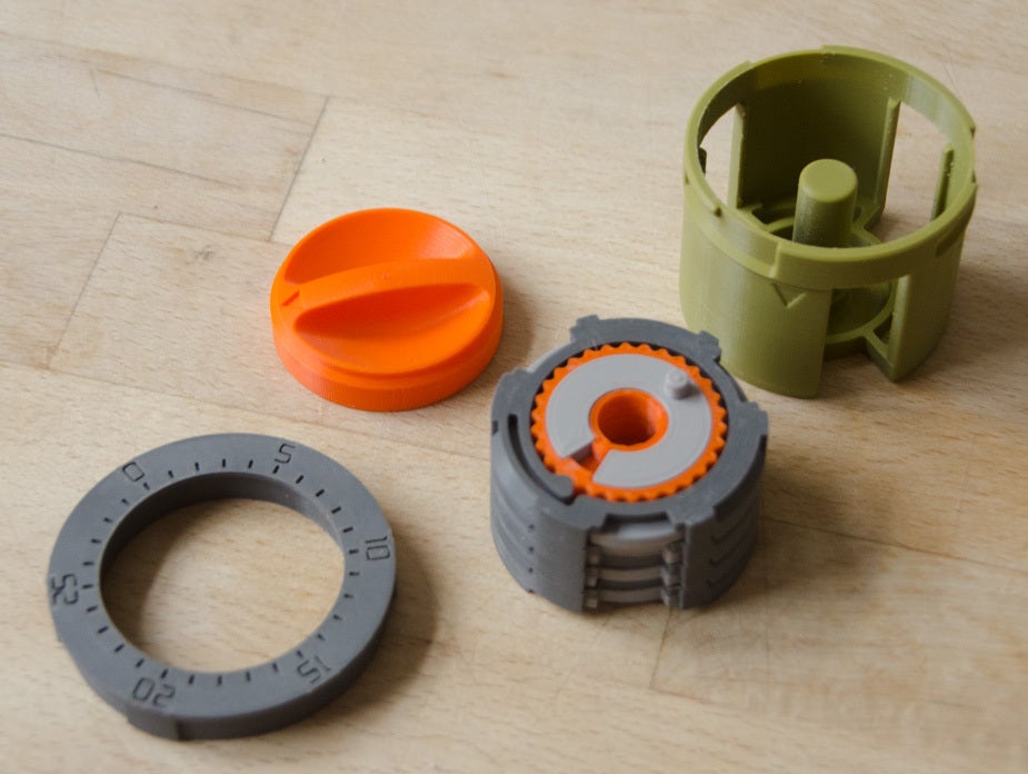
Required Components:
1 x Combination_Setting_Tool
1 x Lock_Caseing
1 x Dial
1 x Dial_Ring
1 x Static_Compensator
1 x Body
4 x Compensator
4 x Combination_Gear
4 x Latch_Ring
4 x Incrament_Ring
Other_Componants:
1 x Test_Dial_Ring (Strongly Recommended)
1 x Stand (Optional)
1) Choose four numbers as your combination. Each of the four numbers can be between 0-29. The same number can be used more than once. eg 19, 11, 28, 11.
WARNING
Try to avoid using neighbouring numbers next to one anther eg 5, 6, 15, 14 as this might be problematic. I need to look into it.
2) Slot one of the Latch_Rings onto the back of the Combination_Setting_Tool, so the three slots on the Latch_Rings line up with the corresponding extrusions on the back of the Combination_Setting_Tool.
note: the slots are not equidistantly spaced so there is only one correct position.
3) Now hold one of the Combination_Gear behind the Latch_Ring but do not engage the teeth yet.
4) Rotate the Combination_Gear until the pin lines up with the first number (A) of your combination.
5) Press the Combination_Gear into the Latch_Ring so the teeth engage. The two pars should hold together.
6) Smear a little grease round the exposed teeth of the Combination_Gear. Without lubrication it is likely the mechanism will not work properly.
7) Place the combined Latch_Ring and Combination_Gear on a flat suface.
Now put a Compinsator in the channel of the Combination_Gear and place an Incrament_Ring over the top. The tooth on the Increment _Ring should engage with the teeth of the Combination_Gear.
8) You now have the first of four layer of the locking mechanism.
9) To create the other three layers of the locking mechanism simply repeat steps 2-7 but changing the number each time. Remember the bottom layer is the first number in your combination, the layer above is the second number etc (see illustration). Use the triangles on the side of the Incrament_Rings to make sure they are linghned up when you stack them. The Incrament_Rings should clip together thus holding the whole locking mechanism together.
10) On the top layer of the locking mechanism use the Static_Compensator rather than a regular Compensator.
11) Place the final Compensator in the channel at the bottom of the Lock_Casing.
12) Being careful that the Latch_Ring on the bottom doesn’t fall off, pick up the locking mechanism and line up the triangles on the side of the Incrament_Rings with the ones on the side of the Lock_Caseing. Once the parts are aligned slide the lock mechanism into the Lock_Caseing
13) Place the Dial on top of the locking mechanism so that the drive pin of the Statc_Compinsator go into the hole in the underside of the Dial.
14) Screw the Dial_Ring onto the top of the Lock_Caseing. There is a mark on the side of both components to help you find the correct alignment quickly. The locking mechanism is now complete.
DO NOT!!! put the locking mechanism into the Body yet.
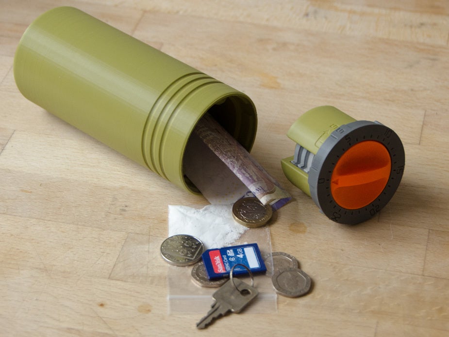
How to use
Before using the safe make sure everything is working as it should.
Repeatedly turn the Dial in both directions as far as it will go to help spread the grease and wear down any print artefacts. If the mechanism is working as it should the top or bottom Latch_Ring will turn as far as it can on its own before it starts turning the next Latch_Ring and so on. If any of the Latch_Ring are turning intermittently there is an issue with friction which will need to be resolved by farther cleanup or lubrication before continuing.
If everything is working smoothly, reset the dial by turning it anti-clockwise as far as it can go. In theory, this should be to 0 however in practice it overshoots to between 28 & 29.
Now rotate the Dial three complete revolutions clockwise and continue turning clockwise till you reach the first number of your combination. You will need to continue turning the Dial about half an increment before you hear the ratchet click into position.
Note: If at any point you overshoot any of your numbers, by even a single increment, you will have to reset the dial and start over.
Now turn the Dial in the opposite direction (anti-clockwise) two complete revolutions, till your back at your first number, and continue turning anti_clocwise until you reach your second number. Again remember to turn that half increment till u hear the ratchet click into position.
Now turn the Dial in the opposite direction (clockwise) one complete revolution, till your back at your second number, and continue turning clockwise until you reach your third number.
Now turn the Dial in the opposite direction (anti-clockwise) directly to your fourth number.
If everything has worked as it should all the Latch_Rings should be aligned with the latch slots of the Lock_Caseing, so there are no obstructions. Be sure to check all three latch slots are clear, not just one or two.
If everything is working as it should, I suggest you reset the Dial and repeat the whole process a few times to check for anomalies and get a feel for the mechanism.
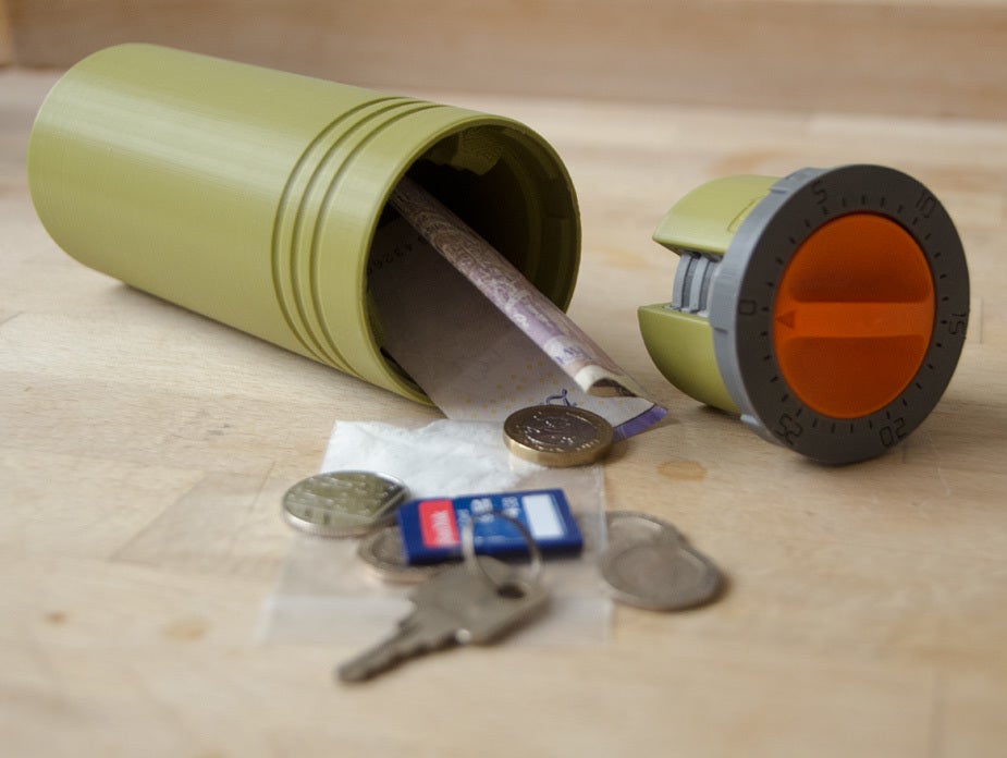
Now you're ready to try the locking assembly inside the Body. Again I strongly recommend using the Test_Dial_Ring as a precaution, as you can remove it and dismantle the locking assembly from the inside out, in the event, it gets stuck and won't unlock.
The locking assembly will need to be in its unlocked position to go inside the Body. To help you align the locking assembly with the Body match up the numbers on the Dial_Ring with those on the inside of the Body. The locking assembly should then slide into position. Once the locking assembly is fully inserted, reset the Dial.
Now repeat the unlocking process, from above. If everything is working correctly you should be able to pull the locking assembly out of the Body, if you're able to do so, you're now ready to replace the Test_Dial_Ring with the Dial_Ring and use the safe for real. :-)
If however, you're still unable to remove the locking assembly after several attempts :(
Turn the Test_Dial_Ring anti_clockwise to release it and use the Dial to pull both parts out. You can now access the inside and unlock/dismantle it part by part. Then you'll have to figure out what the problem is. If you have any problems and leave a comment and I will endeavour to assist the best I can.
:format(webp)/https://fbi.cults3d.com/uploaders/18482441/illustration-file/b9fd2bf7-f0e8-4bf0-9ba4-517e1486febe/MCS_00.jpg)


/https://preview3d-images.cults3d.com/em67hk080t3z7d6asn9vc49hbqlc)
/https://preview3d-images.cults3d.com/tnov2xqdfxbwg1xtzgxuslvt93jl)
/https://preview3d-images.cults3d.com/9l1ofoptz1m0kao7wukyonsiozlh)
/https://preview3d-images.cults3d.com/7qomafeobkzt34jbu9n4egyfsfp4)
/https://preview3d-images.cults3d.com/77o8rk5tb4ctm8vza3x3x25e4enp)
/https://preview3d-images.cults3d.com/y0anqkg6qzyrcf66vac0pssuizpn)
/https://preview3d-images.cults3d.com/jo3v7ktjim06fvg24rovjacwq8nj)
/https://preview3d-images.cults3d.com/kfhkw8z79jlvdbze907l4qe03ndg)
/https://preview3d-images.cults3d.com/bz8v18xows2hq9y0qab1lq7o3177)
/https://preview3d-images.cults3d.com/tdzda3nny217q0w2sigraklty7z0)
/https://preview3d-images.cults3d.com/iwkiec031uunsbtvqh6hc2wi67iw)
/https://preview3d-images.cults3d.com/qr5pbmafuzx6iltuy8gmdncyvvbc)


