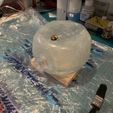
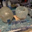
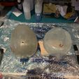
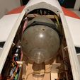
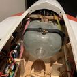
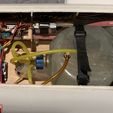
In 2018 I have built the Nick Ziroli design Grumman Panther F9F-5 model as my turbine trainer, which to date I still enjoy flying, with more than 70 flights in total. This model is a conventional balsa/plywood construction model, however during my build, I have used 3Dprinting technology extensively both to assist my build and also make some functional parts to be used on the model itself.
I am sharing some of my related designs here for others to use in their builds of this beautiful model.
This particular post includes my designs for fuel tank molds and related parts.
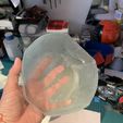
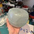
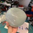
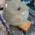
In my model, I have a Kingtech K100 gas turbine for power. Initially, I have designed and made a fuel tank of 3 litres capacity.
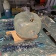
Later on, I noted that I do not use more than 2 litres of fuel even in long flights of 7-98 minutes, so I revisited my design and made a new fuel tank with a 2.3 litres capacity. With this tank, I can easily make 6 minutes flights with plenty of reserve fuel.
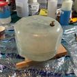
This new fuel tank also provided a nice free volume on top, which I utilized to add an equipment tray to install the fuel pump, fuel filter and valve, resulting in a neat and clean setup with easy access for maintenance or repairs etc.
Both tanks are designed to be placed as rearwards as possible, in between the air ducts for the Turbine air intake, thus as close to the CG as possible. But still, the tank is forward of the CG, and inevitably the fuel consumption during the flight causes a slight shift in the CG of the model. However, in my experience, this shift does not cause any significant handling differences during the flight duration.
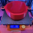
The published files include STL's to print the molds.
In addition to the molds there are files for the dummy tanks themselves, which can be used to print and test fit into your model if you wish to do so.
There is a template to cut the F8 former for the tank to fit in properly.
And finally, for the small tank, there is an equipment tray and feet to install the tray. Please note that for the feet, there is an embedded m3 bolt, which you should modify your code to pause at 6.5mm Z, place the bolts in then resume the printing. These feet are glued on top of the small tank and the equipment tray can be installed and removed with ease using M3 bolts.
DISCLAIMER
The files I share here are to print female molds to produce the tanks using fibreglass or kevlar and epoxy resin. The process requires a certain degree of experience with this kind of composite layup work. If you do not have such experience it is better to ask for help if available or chose a commercially available fuel tank. The end product is a fuel tank, to contain a highly flammable fluid. Any leaks or structural weakness due to producing defects can cause a fire. While my tanks produced from these molds served perfectly, I do not have any control over how these molds are used by others, therefore I can not accept any responsibility or liability if any accident or fire is caused by the use of my design.
Mold printing and preparation
You can decide on your preferred layer thickness to print the molds. The thinner you print the less time you spend preparing the molds. I normally chose 0.15 or 0.2mm layer thickness.
The infill can be anywhere from 25 to 50 per cent, cubic infill worked fine for me. Please note that this method is not suitable for vacuum bagging, I have not tried it myself but most probably the mold will collapse or deform excessively under vacuum.
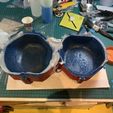
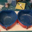
After printing, you need to go through a filling/sanding process to smooth out the mold inner surfaces. My preference is either Rustoleum spray filler primer or 1K filler primer for automotive painting purposes. I normally start with 280 and 320 wet sandpaper, and repeat this filling/sanding process with gradually finer sandpapers, 400 and finally 600, all used wet. If necessary, glazing putty can be used to fill in large voids. When satisfied with the surface smoothness, I use automotive 1K base coat paints to paint the mold and as a final clear coat, I use 2K gloss clear.
When the gloss clear coat is cured completely, the mold should be given a mold release treatment, my preference here is meguiars maximum mold release wax, but you can use whatever you have experience and like to, as long as it is compatible with the 2k clear coat and the epoxy resin used for the lamination.
The molds are printed in halves for each side (front/rear for the 3 litres and top/bottom for the 2.3 litres) I suggest waxing the molds separately, when all parts are waxed, assemble the halves together and install the m3 bolts and nuts, and apply two more coats of wax to the assembled halves. This will ensure that the joint line is also waxed properly.
Layup and assembly
For my tanks, I have used one layer of 100 gr/sqm followed by a minimum of 3 layers of 163 gr/sqm fibreglass fabric and aerospace-grade lamination epoxy. This layup proved to be sufficient strength with a reasonable weight.
As a gel coat, I prefer to use the same epoxy that I use for lamination. Please note that the gelcoat is important for the sealing of the tank.
When the epoxy is cured, remove the bolts and nuts that hold the molds together and carefully remove the molds and smooth out the edges of the tank halves preparing for joining.
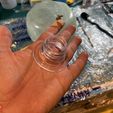
You will need a PET bottle type of fuel tank for fittings. (easily found for gasoline engine powered models).
Drill a suitable diameter hole on top of the tank for the breather line nipple and install the fitting. This has to be done before the final assembly of the tank halves.
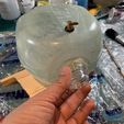
For the main cap, cut out the neck of the PET tank. Sand both sides of the flange (inside/outside) with coarse sandpaper to take out the shine of the PET surface and provide grip for the lamination epoxy/glass cloth. Glue this to the front side of the tank and support with strips or better "donuts" of fibreglass cloth and epoxy. Of course, the surface on the tank itself also has to be sanded a little and cleaned with alcohol thoroughly before this step.
Please note that for the 3 litres tank you can make this main cap assembly before glueing the tank halves together, however, the 2.3 litres capacity tank has a different, and better in my opinion, joining system, but for this tank, the hole should be prepared before joining the halves, and the cap should be glued on only after the tank halves are joined together.
Joining the halves is a bit tricky for the larger tank. you need to glue some small sticks to aid the alignment. When the halves are together, you may tack glue with some cyano and finally, you have to use some fibreglass tape or strips of cloth to wrap along the joint to strengthen it using lamination epoxy.
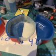
The smaller tank has a much simpler and efficient joining system, one side overlaps the other when brought together. First, make a few dry tests to make sure they fit together good and make necessary adjustments. When ready to glue, use a mix of lamination epoxy and thickening agent like aeerosil or colloidal silica. Mix them together to the consistency of mayonnaise, make sure it does not flow. Apply this paste to the joint line and bring the halves together. Apply more of the paste, forcing it in through the joint line, and then leave to cure, securing the halves together, making sure they do not move.
When joining is complete, make a leak test to the whole of the system (install fuel tubes and submerge all the system into a container full of water, blow into the tubes and watch for air bubbles). If the gelcoat is applied in a proper way and joining is also made good, there should be no leaks. However, it is quite possible and normal to have pinholes in the lamination. Mark all of these leaking spots and patch them up with laminating epoxy. Repeat the leak test until you are absolutely sure that you do not have any leaks.
In my tanks, the large one had some leaks, mostly in areas that I had to sand off the gel coat, and was patched up as I described above. The smaller tank on the other hand, due to its joining system did not have any leaks and I was able to use it right after the assembly.
During my design and making of the first larger tank, I have posted my progress on my Instagram account. The relevant posts are linked below with a short video at the end:
https://www.instagram.com/p/BoCMiG6FsXS/?utm_source=ig_web_copy_link
https://www.instagram.com/p/BoEoFs6lcHn/?utm_source=ig_web_copy_link
https://www.instagram.com/p/BoJ162Wl-RW/?utm_source=ig_web_copy_link
https://www.instagram.com/p/BoPW6NylA09/?utm_source=ig_web_copy_link
https://www.instagram.com/p/BoTspH9lSmE/?utm_source=ig_web_copy_link
https://www.instagram.com/p/BobuQI7luFP/?utm_source=ig_web_copy_link
https://www.instagram.com/p/BohAlr7FyHS/?utm_source=ig_web_copy_link
https://www.instagram.com/p/BowtIpyFLQw/?utm_source=ig_web_copy_link
https://www.instagram.com/p/Boyqc7kFUr3/?utm_source=ig_web_copy_link

/https://fbi.cults3d.com/uploaders/13914830/illustration-file/5dde8eea-7e22-4679-b27e-196c559c13f4/6zL65.jpg)
