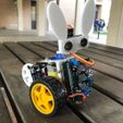
I needed a simple Arduino-based robot for working with schools, and I fell in love with the SCRU-FE design. It is easy to print, cheap to build, uses easily sourced parts, and with the ultrasonic sensor can introduce some programming to the students. Over the years I have probably built a couple of hundred or so with students, and during that time I've slowly evolved my own version to address some of the issues and challenges that came up.
The major changes are:
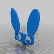
- Added ears. My wife complained that SCRU-FE looked ugly (I disagree) so I figured that if I added ears it would, by definition, become cute.
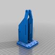
- Redesigned the ultrasonic mount to hold the sensor in place by pressure or screws without any additional components.
- Widened the body. I found that we would have trouble managing the wires and nuts inside the body due to the narrow space, so I widened the body to make things more accessible.
- Strengthened the sensor mount.
- Added holes for cable management.
- Added holes for mounting an on/off switch.
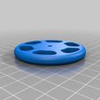
- Converted the rear wheel into a single piece unit and made it wider.
- Inset the nuts for most of the bolts to make it easier to attach.
- Added a slot to mount the battery holder, as there was a lot of variation in hole placements.
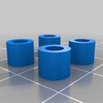
- Made spacers to lift the Arduino from the backing plate. These were originally part of the backing plate, but that required more support, so I've separated them to make things easier to print.
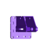
- Added mounting points for attachments on the Arduino mount. This opens up possibilities such as adding a line following unit, different sensors, or a shovel for Sumo.
- Lengthened the body, allowing for the possibility of adding extra weight to reduce tippiness (I presume that is a word).
- Made the ultrasonic mount thicker.
- Added a bit of extra thickness around the motor mounts.
You can print this with minimal support (mostly some for the hole where the servo is placed), but I tend to use a bit more just to making this a bit smoother. Drilling out the holes probably won't be needed, but if it is all holes are 3mm, and nothing needs to be tapped.
Hardware
6 x M3 10mm bolts
3 x M3 15mm bolts
1 x M3 20mm bolt
5 x M3 25mm bolts
4 x M3 10mm countersunk bolts
17 x M3 nuts
2 x M3 washers
2 x M3 nylock nuts
Six of those nuts and bolts are just placeholders for the optional mounting points and can be left out, but adding them will make it easier to add attachments later (as you won't need to remove the motors to get the nuts in place).
I'll add some more assembly details later, but mostly it just follows the design set out by SCRU-FE. One thing I did find was that I could solder the wires to the motors in advance, as well as solder up one of the wires to the switch. This reduces the required soldering to two joints during the session, and if I was with a class where soldering wasn't practical I could do that part for them without losing too much session time. I also found that it was easier to get screwdrivers than spanners in sufficient numbers to suit a big group, so I've included a simple spanner design which works well for the M3 nylock nuts.
Edit 11 April 2019: I found that the spacers stl was corrupted, so I've uploaded a new version. I've also added the basic Arduino code I've been using. If you use the code the ultrasonic uses analog pin 4 for trigger and 5 for echo. On boot it will run through a quick test sequence:
- Move servo left
- Move servo right
- Move servo to middle
- Drive forward
- Drive back
- Turn left
- Turn right
This allows you to check to see if the motors are wired up correctly or if you need to swap the wires around.
After that it returns to the standard SCRU-FE behaviour.
Edit 18 April 2019: I've uploaded the 123D files to make modification easier.

/https://fbi.cults3d.com/uploaders/18597515/illustration-file/7c4bb7aa-c2b5-43d2-a83b-380809619e9d/wide-bodied_scru-fe.jpg)
