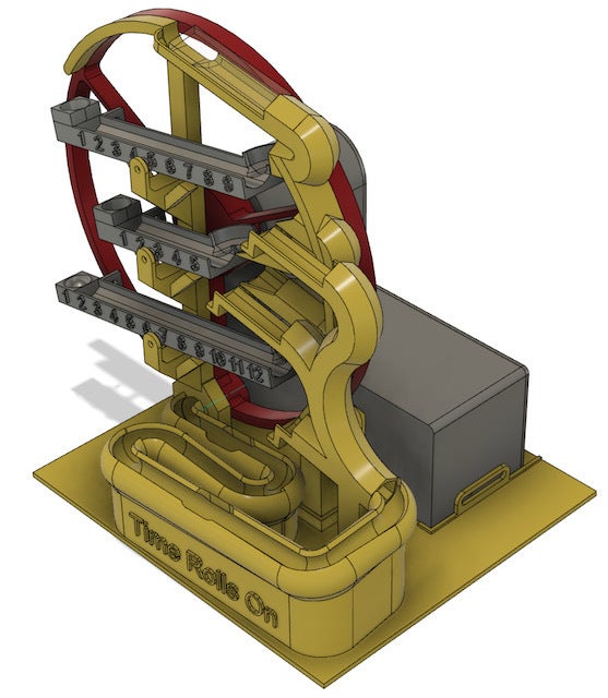
This is a “simple” 3d printed ball clock that uses 3/8” diameter steel bearings to count the time. (I put “simple” in quotes because designing this thing and perfecting it has been anything but simple.)
My goal was to create a ball clock that could be 3d printed relatively easily on an Ender 3 class 3d printer and assembled without too much fuss. I’ve seen and taken inspiration from other ball clocks (particularly 3Dadicto’s clock: https://www.thingiverse.com/thing:4786491) but they all seemed larger and more complex than what I was going for. This version has only a handful of models that need to be printed (all without supports) and the final assembly is pretty easy.
Additional materials needed:
* 30x 3/8” ball bearings (at minimum)
* 10 M3x6 screws (or longer)
* 1x M2.5 set screw
* 1x Arduino Nano (or equivalent)
* 1x DRV8825 stepper motor (or equivalent)
* 1x Nema 8 (20x20x38mm) stepper motor (the shorter one lacks the necessary torque)
* 1x 5.5mm x 2.1mm DC power supply jack (or equivalent)
* 1x 12v power supply with 2.1mm x 5.5mm plug (or equivalent)
* (Optional) 1x3" x 3.5” breadboard PCB
* (Optional) Mounting sockets for the Arduino and the stepper driver.
* (Optional) JST connectors for the motor and the power leads.
Printing instructions:
None of these models should be printed with supports but it’s pretty important that your printer be reasonably well dialed in. Your build plate needs to be very level because too much skew in the prints can prevent the clock from working. I recommend printing on glass, particularly for the lift wheel, because you want the surface to be as flat and smooth as possible.
WARNING! You will probably want to print the motor housing shell and back and the mounting hub in PETG (or ABS) because the small Nema 8 motor can run hot and I’ve had these motors get hot enough to deform PLA.
Also, when you print the clock base (which can be printed in PLA), you are going to want to print at least the layers that make up the ramp using as low a layer hight as possible (for example 0.12mm) because if the ramp isn’t perfectly smooth, the little balls will occasionally get stuck on the ramp. I used PrusaSlicer’s adaptive printing layers feature and that worked well for me.
All of the other parts can be printed using PLA with normal settings (perhaps 20% infill with 3 perimeters but really anything will probably do the trick.)
Preparation:
Once you’ve printed all of the parts and cleaned them up, you may want to take some time to sand the ramp on the base and make it as smooth as possible. If you don’t do this, balls may occasionally get stuck on the ramp. Take your time and make sure that you test it by lowering a ball VERY slowly behind your finger or a tool to make sure that there are no flat spots or bumps that will cause the ball to get stuck. Despite my best efforts, I still find the last ball in the queue occasionally getting stuck. For this reason, I have suggested you use at least 30 balls, giving you a couple of extra balls in the ramp even when the clock reads 12:59. Having 2 or 3 extra balls ensures that even should one ball get stuck, there will still be one ready to be picked up by the lift. That stuck ball will get knocked loose the next time balls are returned to the queue. Also, I find that if there isn’t enough pressure behind the lowest ball, it may not be picked up by the lifting wheel. Having extra balls in the queue helps ensure that the ball will be picked up every time.
Electronics:
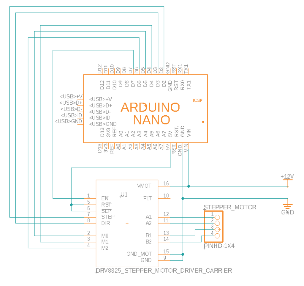
I’ve included a wiring diagram to wire up the Arduino Nano to the DRV8825 stepper motor driver and the driver to the stepper motor. It’s a pretty simple wiring job. Just take your time, making sure you correctly identify all the pins (they may not be in the order you expect) and you’ll get it. A breadboard and JST connectors aren’t necessary but they can really help. I’ve also included a couple of other images showing wiring and pin layouts that can help with this.
WARNING! You will need to make sure you set the proper VREF on the stepper driver before you try to hook it up to the stepper motor. Nema 8 motors need very little current and if you set the VREF too high the motor will run WAY too hot. You could easily melt the motor housing or damage the motor if you skip this step. You’re going to want to set the VREF to 300mV or less. Lower is better. Set it just high enough that the motor doesn’t stall or skip steps. Even if you get it right, your motor will probably run at around 55 to 60c so make sure you’ve printed any part that comes in contact with the motor out of something that won’t deform at those temps. Here’s a page that can help if you don’t know how to set the VREF: https://e3d-online.dozuki.com/Guide/VREF+Calibration+guide+DRV+8825/94
Now would also be a good time to flash the Arduino with the sketch I’ve provided and calibrate the clock. Note that the internal clock on an Arduino is notoriously inaccurate so you WILL need to calibrate if you want the clock to be accurate. You can find instructions in the code. Even calibrated, you’ll probably find that the clock will drift one way or another by a second every day or two since environmental factors such as temperature can affect the Arduino's internal clock. If that’s a problem for you, you’ll need to come up with some way to synchronize the time such as an external RTC module and adjust the sketch to work with it. I haven’t done that because this was good enough for me but if you choose to go that route, leave me a message. I’d love to hear how it goes.
Assembly:
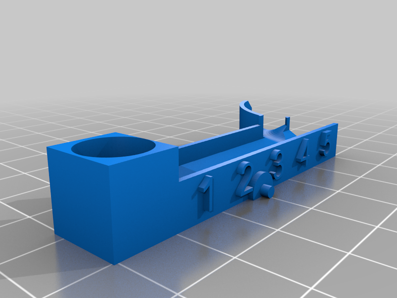
The counting trays should snap in to their cradles with a little encouragement. The hours tray goes on the bottom, the tens tray goes in the middle, and the minutes tray goes on the top. Make sure that they pivot easily. I’ve included a test pivot model that you can print to make sure that your trays will attach and move correctly before you commit to printing the full base. Use it! If the trays fit too snugly then you may want to reprint them with a lower outer wall extrusion or perhaps with a little inverse horizontal expansion. The trays should tilt VERY easily.
Put one ball in each of the little cups on the left side of each of the counting trays. Those balls are counterweights that make sure that the counting trays will reset to their normal orientation (leaning to the left) after they empty their balls. Each of the counting trays also has a hole in the back to receive an M3 bolt. This allows the counterweight to be tuned. You want each tray to stay still (or nearly still) when the first marble rolls on to the tray. If it dips forward more than a jiggle when the ball rolls in, then you’ll want to add weight by backing out the bolt until the tray stays still. Use a longer bolt or perhaps add a nut if you need more weight. The tray should stay tilted to the left even when the front row is full of balls. Once the count is full, the next ball that enters should cause the tray to tip to the right and empty all of its balls. If the tray doesn’t tip to the right with the last ball or if it rebounds before all of the balls have left the tray then you'll need to lighten the counterweight by screwing the bolt farther in or swapping it for a shorter (lighter) bolt. This will take some experimentation but if it’s not tuned right, the clock will drop balls, or perhaps not even work at all.
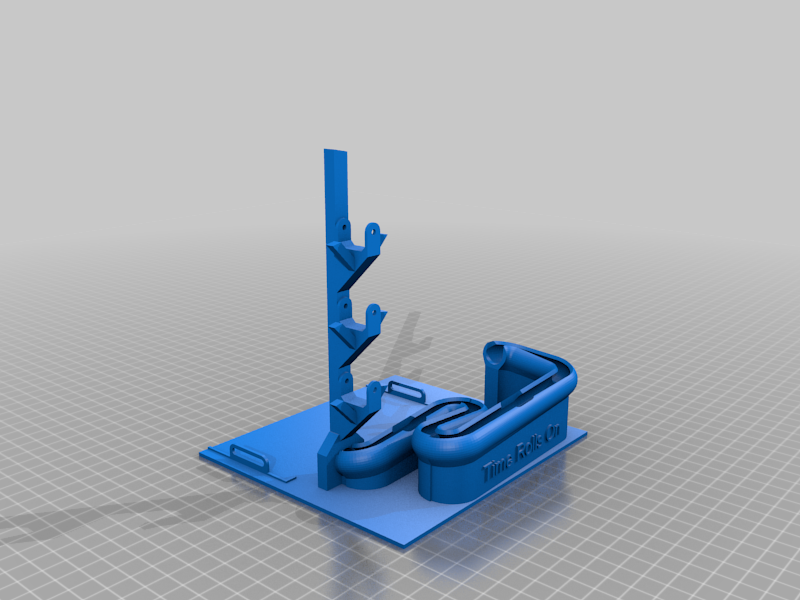
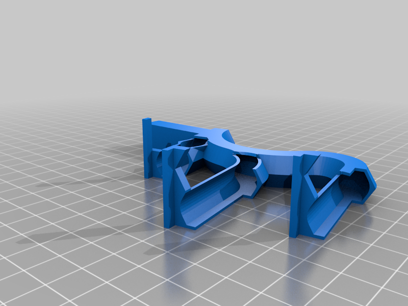
Next, glue the input tower and the ball return pieces together, using the CAD photos as a guide to where they go. The return ramps should line up. After these two pieces are glued together, you can glue them to the base, just make sure that all of the ramps line up and the balls can easily travel down the ball return ramps and down to the ramp on the base. You’ll want to test before you glue! Tolerances are pretty tight so you may find you need to do some sanding or other post processing to make sure all of the ramps are clear.
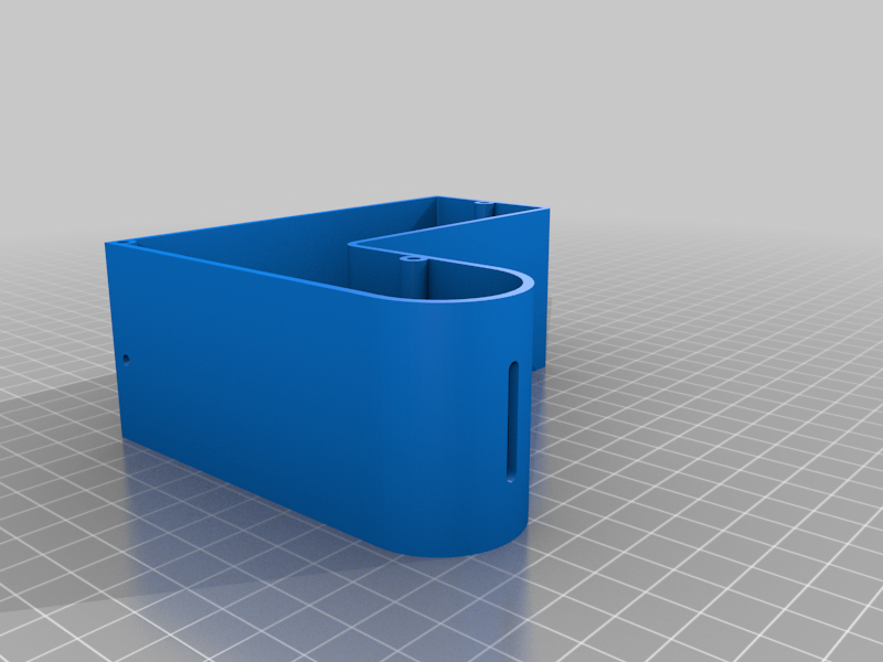
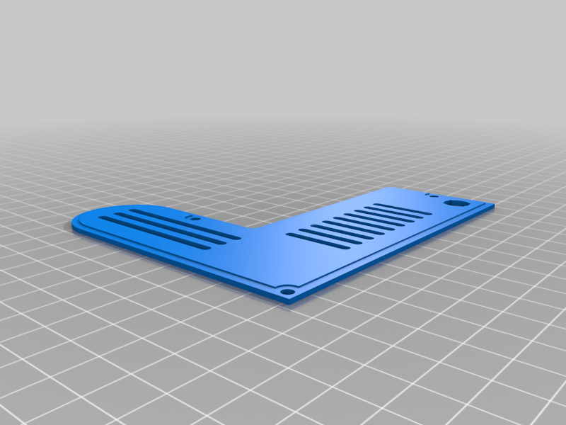
Assemble the motor housing with the electronics and the stepper motor. If you’ve used a breadboard to mount the chips, you can use M3 screws to attach the breadboard to the standoffs inside the shell. Mount the power socket to the back and the stepper motor to the inside of the shell so the spindle protrudes through the large circle. Then attach the back to the shell using 3 M3 screws. Note that all of the screws used in this model self-tap. None of the receiving holes are pre-threaded.
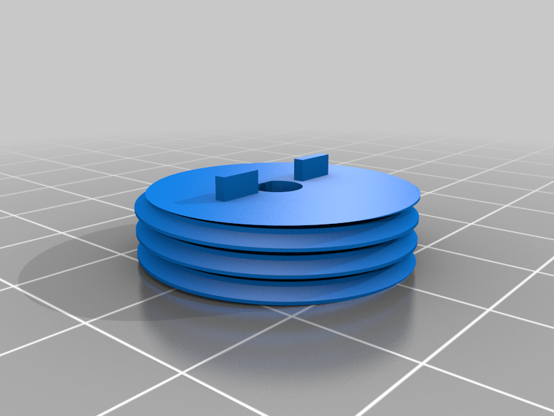
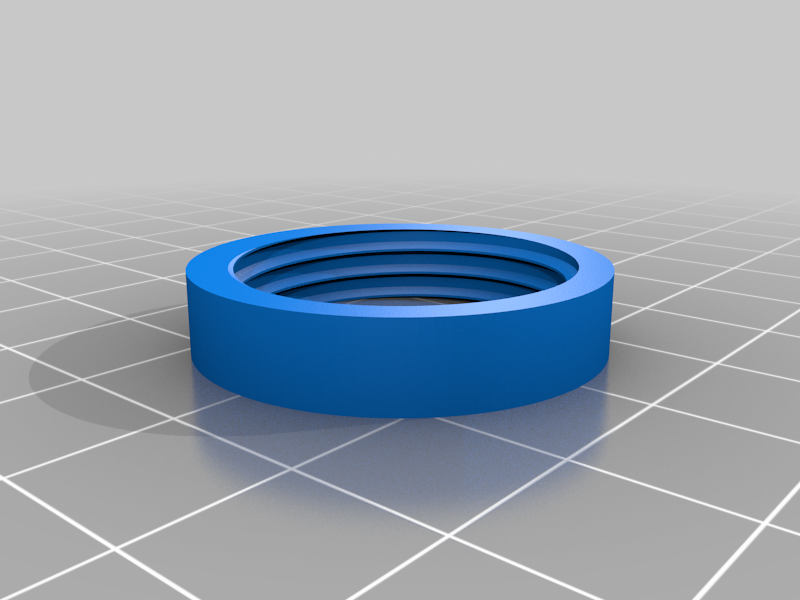
Attach the mounting hub to the stepper motor’s spindle using a set screw. The tabs on the hub should face the motor. The hub should be flush (or nearly flush) with the end of the spindle. Make sure that the hub turns freely and that it is as close to perpendicular with the spindle as possible. If it wobbles too much the lift wheel may bind.
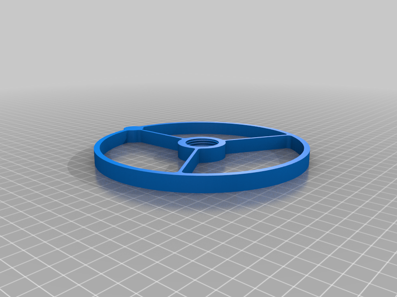
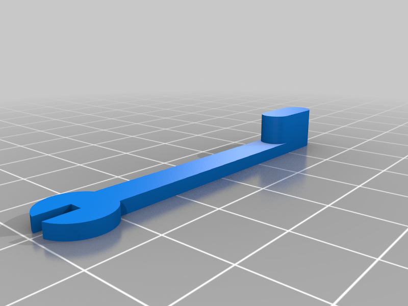
CAREFULLY screw the lift wheel onto the mounting hub. NOTE that the threads go in the OPPOSITE direction from normal threads. You will need to turn the wheel COUNTERCLOCKWISE to attach it. This is to keep the wheel from unscrewing itself from the hub during operation. You can print and use the hub wrench to keep the hub from turning while you attach the wheel. Be careful not to over tighten it. Just barely finger tight is tight enough.
Now it’s time to place the motor assembly on the base and slide it up next to the ramps. You will have to experiment with how close to slide it. Here is where having a really level print bed matters the most. Even with an exceptionally well calibrated printer, your wheel will probably be ever so slightly out of alignment and rub up against the model in a few places. You want it to be close enough to the bottom ramp that it picks up the balls one at a time but far enough away that friction doesn’t bind up the motor.
Note that the wheel is designed so that a ball will sit just a little bit proud when it is being carried in the lift pocket. This means that the wheel doesn’t need to be slammed up against the clock. It also means that the balls will be captured more smoothly than they would if the pocket were deeper. You should have a gap of at least a millimeter or two.
Test it for a while. Once you’re happy with the position of the motor housing and the lift wheel, you can secure them in place with a couple of M3 screws.
Setting the Clock and Reading the Time:
The time is read from the bottom up. The bottom tray counts the hours. The top two trays together count the minutes. The middle tray counts the tens digit (one ball added every ten minutes) and the top tray counts the ones digit (one ball added every minute).
Setting the clock is as simple as making sure the lift wheel is in synchronization with the second hand on your reference clock and then putting the correct number of balls in each of the trays so that it reads out the correct time.
A new ball will be picked up at half past the current minute (the 30 second mark) and it will be deposited on the top ramp at the start of the next minute.
Notes:
Overall dimensions: 215mm wide x 140mm deep x 165mm high
Imperial units (rounded up to the nearest 1/4”): 8.5” x 5.75” x 6.5”
https://youtu.be/CMkGBnBVC-U
:format(webp)/https://fbi.cults3d.com/uploaders/16177582/illustration-file/d6025ba7-8bbd-4c9b-b4a5-ebd4f8c7bc04/photo.jpeg)


/https://preview3d-images.cults3d.com/cc64htr4wrvihr8htdadrz9lnsaq)
/https://preview3d-images.cults3d.com/oh8r6x7cv8uv982bi77g3kv2a5rs)
/https://preview3d-images.cults3d.com/nt1i39udn6q07kimx1xvvqktlmdb)
/https://preview3d-images.cults3d.com/3gr32i5memmgm2n622lc3cba5w5p)
/https://preview3d-images.cults3d.com/variants/0uic61afbfycu4tobof9kulq01vg/cbbb7afd8a0ec9560f7f7940881f98c31dcb04582a03efcc135070de65821be8)
/https://preview3d-images.cults3d.com/variants/ya1z4qvtanw37cvxorkbgl1v3txe/cbbb7afd8a0ec9560f7f7940881f98c31dcb04582a03efcc135070de65821be8)
/https://preview3d-images.cults3d.com/variants/3ort2mzgmjpghx6wxtfmm7zeeg7t/cbbb7afd8a0ec9560f7f7940881f98c31dcb04582a03efcc135070de65821be8)
/https://preview3d-images.cults3d.com/cdn80c1ev1hn7239x6ltm8ujqsxa)
/https://preview3d-images.cults3d.com/variants/wnuo2zh413wwoo8wpl7bear6tqtw/cbbb7afd8a0ec9560f7f7940881f98c31dcb04582a03efcc135070de65821be8)
/https://preview3d-images.cults3d.com/variants/ku8yc5hfarq0phlb9kcnkadgw21q/cbbb7afd8a0ec9560f7f7940881f98c31dcb04582a03efcc135070de65821be8)
/https://preview3d-images.cults3d.com/6h6dksz81iwguglwpzxjo46m3sxg)
/https://preview3d-images.cults3d.com/variants/oemt714zlm5t0cyrtowo4k51yjoe/cbbb7afd8a0ec9560f7f7940881f98c31dcb04582a03efcc135070de65821be8)
/https://preview3d-images.cults3d.com/kibtu9dh88v5geu8ft4ascgxj6s1)


