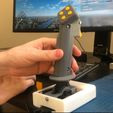
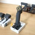
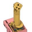
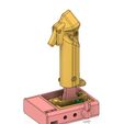
Flight stick for flight simulator games. Appears as a regular USB joystick on Windows and Mac, thanks to the Arduino Pro Micro inside. I will upload the simple code below.
Joystick position is sensed with two hall effect sensors.
Pitch and Roll axes have independent springs or rubber bands.
Goes together with 3M bolts and nuts. If you want to be fancy, you can print version B or C, which use 7 mm and 17 mm bearings, respectively.
Throttle unit: https://www.thingiverse.com/thing:4578169
Pedals: https://www.thingiverse.com/thing:4578174
Explanation video: https://youtu.be/na3NeZJYK3g
Build Instructions
Print all parts.
If you don't have bearings, print Ver A of the applicable files. If you have small 7mm x 3mm (OD*ID) bearings that go on the 3M bolts, print Ver B, if you have the larger 17mm x 6mm bearings, print Ver C.
The joystick works without any bearings, but can develop some slop in the axes after a while. I ended up using Ver C with the large bearings.
The Shaft and Hinge Cam should be printed quite slow, to get a smooth outer surface. They will slide against other parts.
All parts can be printed without supports. Except for the Joystick Grip sides and Shaft Ver C, which needs supports where touching the build plate.
Glue the magnets into the Hinge piece. Check the video. The two magnets should be attracting each other when in place (S facing N). Other than that, orientation doesn't matter.
For Ver C, the pitch axis magnets mount onto a seperate magnet holder.
Mount Shaft to Hinge.
Ver B: first, push bearings onto both sides of Hinge.
Ver A and B: add nuts to the hexagonal holes in hinge (you can glue them if you want). Run a long M3 bolt through the whole Hinge piece, and the Shaft piece, adding washers in all locations you can. The bolt must not be so long that it protrudes from the other side in between the magnets. You can add washers or a nut on the other side to adjust the length.
Ver C: Push in two bearings to Hinge. Put Shaft through Hinge, and then slide in the Axis from the side with the magnets. If the Axis doesn't seem solid enough, you can add a M3 bolt through the hole in the side of Shaft.
Solder wires onto Hall effect sensors.
On my hall effect sensor, the pins were VCC, GND, and Signal in that order.
Mount Hall effect sensors
Bend the wires and mount one on the tip of the thin pedestal in Base, and one on the pedestal between the magnets in the Shaft+Hinge assembly. They will stay between the magnets but rotate around their axis.
In Ver C you mount the pitch sensor onto the end of Axis. After this you glue down the Magnet Holder to Hinge so that the magnets flank the sensor on both sides.
You can tie down the loose wires with hot glue to add strain relief.
Glue Hinge Cam to Hinge
It goes in the notch near the back.
Insert Hinge Cam Slider to Hinge.
It slides in the rectangular slot and will slide against the V shape in Shaft. Add two rubber bands or springs, and a drop of grease on the moving surfaces. Your pitch axis should now have nice spring tension.
Mount the potentiometers and switches in base. Solder wires to the pots three leads, and to the switches NO and Common. Push on the Trim Knob.
Mount Hinge onto Base with M3 bolts. Ver A and B have slots for M3 nuts. Add washers in between where necessary. Ver C has larger holes so you can add brass inserts, or perhaps heat up M3 nuts and embed those.
Mount Cam Arm onto Base with a bolt. It should go through the slot. Add a bolt and a nut to the small hole in the wall in Base, and add a rubber band or spring between that bolt and the hook in Cam Arm. Add some grease. This Cam Arm should now add spring tension to your roll axis. Your joystick shaft should now move in all directions and return to the middle.
Add a bolt for the Trigger and use hot glue to glue a microswitch to Joystick Grip Left Side. Make sure the location is good so you get a perfect trigger motion.
Slide in Thumb button and glue in a microswitch for it in Joystick Grip Left Side.
Add four Face Buttons to Joystick Grip Face Buttons Mount Plate, and hot glue four microswitches to it. Take the metallic switch arms off before gluing. (Check video to understand)
Add wires to all microswitch Common (you can solder all these together, and run one wire out), and to NO.
Glue Mount Plate onto Joystick Grip Left side.
Screw Joystick Grip Left side and Right Side together, on both sides of Shaft. Run the wires from the switches out the bottom.
Solder wires to Arduino.
Commons go to Ground. VCC goes to 5V and GND goes to GND. Pot ends go to GND and 5V. Hall effect sensor signals go to A0 and A1, pot sweepers go to A2 and A3 etc. Switch NO all go to 2, 3, 4, etc.
You can set which button and axis is which in the sketch later.
Mount Arduino to the back of Base.
Close the Base Cover.
Program Arduino. You can use this hack to change the reported Device name: http://liveelectronics.musinou.net/MIDIdeviceName.php You will have to do this if you wish to use the throttle device at the same time, the games don't understand it otherwise. Or perhaps you could use UJR.

/https://fbi.cults3d.com/uploaders/19244030/illustration-file/60dfe8f4-4af8-4a9f-8c54-c3762690dc58/Screen_Shot_2020-08-22_at_23.09.42.jpg)
