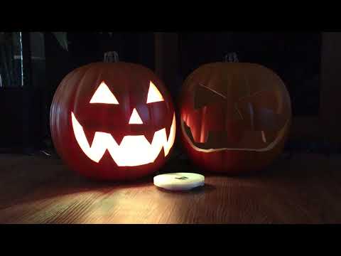
I love Halloween! Each year I try to up my game by adding something new and this is my effort for 2021.
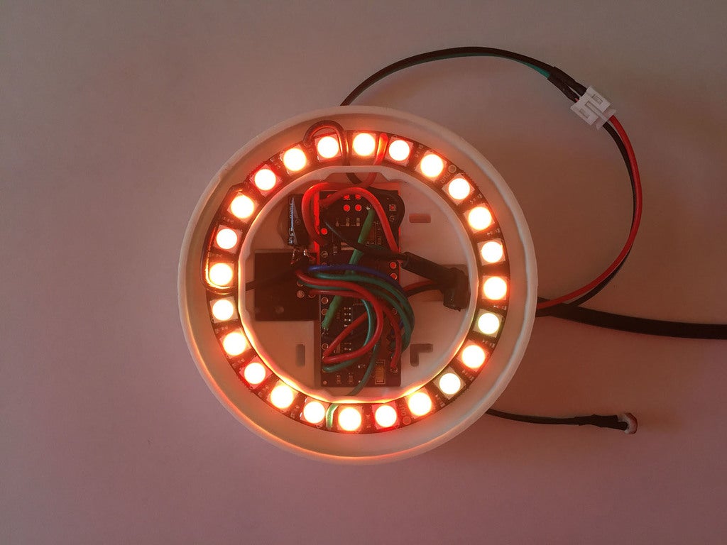
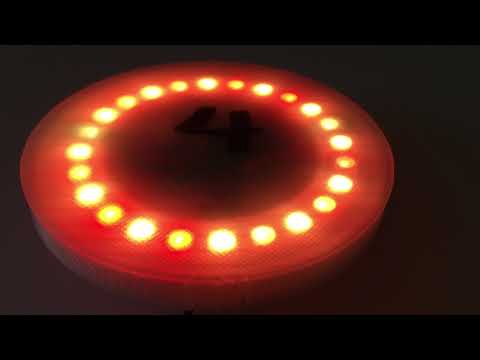
This is an Arduino Nano controlled neopixel LED ring with a NRF24L01+ radio transceiver and LDR light sensor wrapped up in a neat package that can be added to a pumpkin or other prop.
Let's just call it the "puck".
When powered-up the puck runs an orange flickering effect to simulate a candle. Commands issued over radio can change the color, playback mode, or turn it off and on. A command can be issued for a specific puck or every puck in range. The light sensor can put the puck into sleep mode if ambient light is too high.
The reason I used a radio module instead of Bluetooth, which is more common in this sort of project, is so multiple pucks can be issued commands simultaneously, since no handshaking or connections are required.
I am by no means a hardware or software wiz so assume this project could have been done better. That said, it works a treat.
This is a very technical project and great for learning. If you have problems I'm probably not going to be available to help you, I have a other things to do! So do as I do and Google it.
METHODOLOGY
My Halloween display is managed by a Raspberry Pi based controller running custom software written in Python 3. I have included a Python library and sample script. You could use any sort of hardware capable of utilizing a NRF24L01+ module as a controller, like another Arduino or other type of computer. But if your controller doesn't run Python then you'll need to write your own controller software.
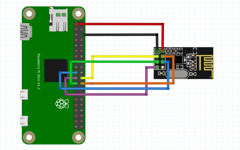
The Raspberry Pi controller has a radio module attached to it for issuing commands, though I used the slightly different NRF24L01+PA+LNA model which offers better range. You could also use the same NRF24L01+ module as the puck uses, the wiring and software are exactly the same.
In practice my display has several jack-o-lanters with pucks installed. The Pi controller can send a command which changes the effect of specific pucks or all of them at once. This is to make the pumpkins react to what's happening in my display for maximum spookiness.
PARTS LIST
For 1 Puck
1 x Arduino Nano 168 or 328p (get ones without pins installed)
1 x 24 X WS2812B 5050 RGB LED Ring
1 x NRF24L01+ radio module
1 x 10 uf capacitor
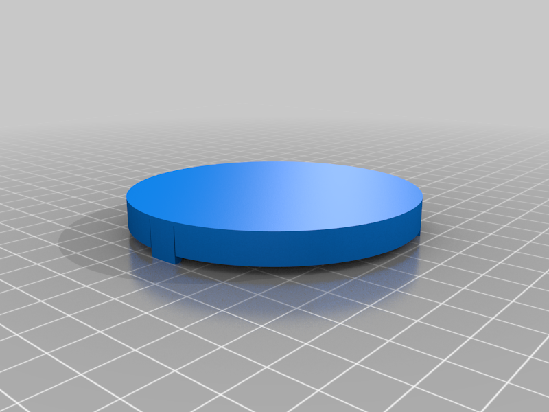
1 x Printed Base
1 x Printed Lid
Bunch of 22 AWG wire
Optional for Light Sensor
1 x LDR Photoresistor 5539 (you could use a different variant and adjust the resistor and level values in the code)
1 x 10k Ohms resistor
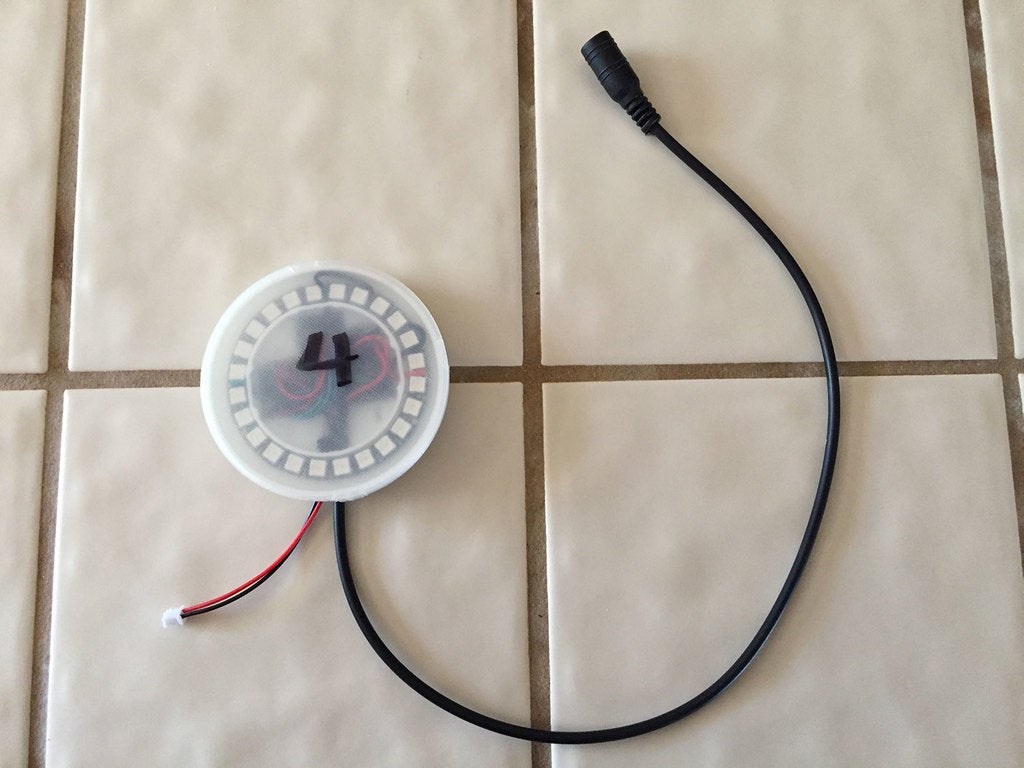
Optional sensor and power connector pigtails.
Optional zip ties to secure pigtails and mount the puck
RADIO
The puck uses a NRF24L01+ radio module. They're cheap and work great, but you must add a 10 uf capacitor bridging the VCC and ground pins or the performance will suffer greatly. Since the puck only receives signals (currently) these tiny radios work well at low power modes.
My Pi controller uses a high-power variation NRF24L01+PA+LNA module since it's responsible for sending the commands. But the same NRF24L01+ module used in the pucks can be used for the controller if range isn't an issue. The controller radio module should also have a 10 uf capacitor bridging the VCC and ground pins.
There's a lot of wiring to connect these radio modules. Quality of the soldering job is import, as is the cleanliness of the solder pads. Be varned.
For this to work reliably the wiring must be good, the power supply ample, and all the t's crossed.
ARDUINO CODE
Included is the Arduino software. It was written for Nanos so mileage may vary if used on other boards. I've installed it on both 168 and 328p versions, though for the 168s you'll need to make sure that variable 'DEBUG' is false otherwise it won't fit. DEBUG just turns on serial monitor output for testing purposes, I'd recommend it be off for deployment anyway.
Required Libraries
RF24 by TMRh20
I used v1.4.1 which was the latest at the time.
LowPower_LowPowerLab by LowPowerLab
I used v2.1.0 which was the latest at the time.
This is to facilitate the sensor-induced low power mode, with the idea of conserving battery power if you run it off batteries.
There're a couple things you can configure before flashing your Arduino:
rf24_rx[5] - Is a 5-character channel that is the unique id for each puck, for individual addressing. Give each puck a unique number but leave the first three characters unchanged. Do not use 0 for the ID because that's used for specifying all pucks.
Example: {'O','C','T','0',2'} or {'O','C','T','3','1'}
LDR_LEVEL - Is the light sensor sensitivity. Higher values equal less sensitive. Adjust this to your preference or if you used LDR sensors or resistor with different values. Where it's at now works well for me.
DEBUG - Turns on/off serial out put for debugging.
SENSOR - Turns on/off light sensor reading and response. Setting to false will save you some space.
RADIO - Turns on/off radio functionality. Setting to false will save you lots of space.
PYTHON CODE
Included is a library and sample script. The library formats the communication payload and has lots of functions to simplify sending commands.
Required Libraries
py-nrf24 - https://github.com/bjarne-hansen/py-nrf24
This is the radio communication library -- super important to use this particular nrf24 library.
In fact, this project contains most of the technical knowledge used in this project and is an invaluable resource.
pigpio - https://abyz.me.uk/rpi/pigpio/
You'll need to have PIGPIO installed and have it's server running.
pigpio daemon - https://abyz.me.uk/rpi/pigpio/pigpiod.html
This is the pigpio server.
struct - Nothing fancy, use pip3 to install.
PLAYBACK MODES
In addition to the default orange flickering candle effect, there are other modes and options built-in.
Playback modes are: flicker, pulse, strobe, solid, rainbow, fade out, fade in, off.
flicker The classic candle effect.
pulse Fades to black and back again.
strobe Blinking strobe light effect.
solid A steady color and brightness.
rainbow Fades through rainbow of colors.
fade out Fades to black.
fade in Fades up from black and continues previous display mode.
off Turns off the LEDS. If the mode is currently set to flicker it will "flicker out" naturalistically. For all other modes it will just turn off.
LIGHT SENSOR & SLEEP MODE
The light sensor is totally optional. If you don't install one it'll still work just fine. In the Arduino code you can adjust the sensitive by changing the LDR_LEVEL value; higher numbers require more light to trigger sleep mode.
When sleep mode is triggered the lights will turn off and the Nano will enter low power mode for 8 seconds. After 8 seconds it will meter the light value again and either enter another 8 seconds of low power or wake up and continue the routine. This is primarily to conserve power when you're using batteries.
ASSEMBLY & WIRING
This part separates the men from the biddy-babies.
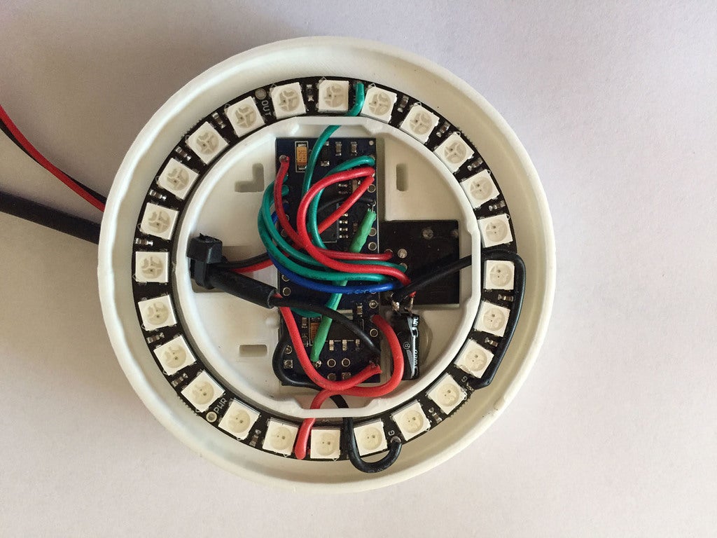
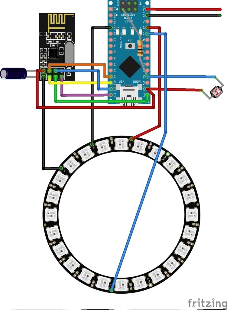
Both the radio module and Nano fit into the base upside down, so the wiring is installed from the bottom of each, adding to the fiendish complexity, because I love you. There is a schematic image included, but it depicts both parts top-side up so you'll need to adjust accordingly.
Before doing any wiring first test fit the radio module, nano, and led ring into the base and get familiar with it. The base has wire management for the LED ring wires and a groove for the radio capacitor to nestle into.
Here's my recommend assembly order.
Do the radio module and Nano wiring first, outside of the case. Fit the pieces in place, route the LED ring wires, and make the last few solder connections in situ.
Inspect the radio module. Clean any gunk from the solder pads and snip off excessively long leads at existing solder points.
Snip capacitor leads to around 12mm length and solder to the radio module VCC and ground pads. Remember that the radio module is top-side down! Fit the radio module into the base and bend the capacitor over the fit in it's groove. Remove the radio module from the base to continue wiring.
Solder the radio VCC and ground wires directly to the capacitor leads. Solder the five radio communication wires to their pads.
Install the resistor to the Arduino, remember it's going in topside down! You may need to wrap the resistor leads in shrink tube. Solder the radio and sensor wires to the Arduino.
Solder the LED VCC, ground, and data wires to the Arduino. Depending on what sort of power connector you're using, you may solder the VIN and ground leads now or wait till the Arduino is installed into the base.
Position the radio and Arduino into the base. Apply some hot glue to the capacitor groove and seat the capacitor -- this will keep the radio module in place.
Run the radio ground wire, LED VCC, ground, and data wires through the wire hold-downs. Run the sensor and power lines through the wire channel.
Position the LED ring into the base and solder the data, VCC, and two ground wires.
Put a zip-tie around the power and sensor wires so that tugging on them won's put strain on the solder points.
Snap the lid on and cross your fingers.
The base has slots to run zip ties through for mounting the puck.
VIDEOS
https://youtu.be/DIzgVRe7BfY
https://youtu.be/Q1ulS2pkiDw
https://youtu.be/GZHeG5a5GYc
:format(webp)/https://fbi.cults3d.com/uploaders/13850608/illustration-file/2faf4788-75be-4d9d-bc06-ac7b5fff395c/IMG_3441.jpeg)


/https://preview3d-images.cults3d.com/wvk9x09os4eafis6k9vaidin998l)
/https://preview3d-images.cults3d.com/variants/jaapk2sp424spxbj8gmwvv5x6amd/cbbb7afd8a0ec9560f7f7940881f98c31dcb04582a03efcc135070de65821be8)
/https://preview3d-images.cults3d.com/5xfrqcfi8rddq1sjiy278w7z244m)


