Step 1: Acquire the following
Printed parts:
4x Outer connector by Octovir (see ancestry)
4x Frame Vertex with Integrated Motor Mount by Octovir (see ancestry)
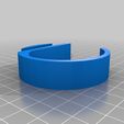
4x (+spares) Quad Leg
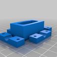
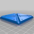
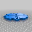
1x Quad Center Top
1x Quad Center Bottom
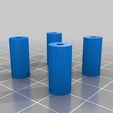
1x Quad Standoffs (set of 4)
Ordered Parts (all prices include shipping/tax for me; these are exactly what I used and paid):
Multiwii Controller Board $40.97
http://www.goodluckbuy.com/mwc-multiwii-lite-4-axis-x-mode-flight-control-board-quadx-w-ftdi-basic-breakout-.html
Motors (4 pack) - $41.37
http://www.goodluckbuy.com/a2208-17-1000kv-outrunner-brushless-motor-for-rc-helicopter-multicopter-4-pack.html
Radio – $65.57
http://www.goodluckbuy.com/6ch-2-4ghz-radiolink-transmitter-and-receiver-lcd-prog-t6ehp-and-r6eh.html
Battery Alarm - $4.10
http://www.goodluckbuy.com/new-rc-lipo-battery-low-voltage-monitor-alarm-buzzer-w-led-warning-light.html
Battery Charger - $14.92
http://www.goodluckbuy.com/chargery-power-320b-li-po-balance-charger.html
Battery - $18.91
http://www.goodluckbuy.com/ge-power-2200mah-11-1v-25c-lithium-polymer-battery-for-rc-model.html
Speed Controller (4x) - $46.03
http://www.hobbyking.com/hobbyking/store/uh_viewItem.asp?idProduct=2161
Props (set of 4) - $16.69
http://www.completeheli.com/Gaui-330X-8-Propellers-8A-8B-Neon-Green-G-210802
Total $248.56
Local Parts:
4x 12in 5/16 rod (1 4ft wooden dowel)
4x 9in 5/16 rod (1 3ft wooden/metal dowel)
Wire and Connectors
M3 screws for motor mounting
#4 or M3 screws for frame assembly
Shrink Tube
Velcro
Note: Consider ordering a spare set of props. You will need them if you are learning to fly.
Step 2: Read (Skim?) the documentation
My radio and Multiwii board did not come with documentation. The following are decent resources online for getting wiring and software setting information.
NEWBIES GUIDE to setting up and using the CRIUS MWC MultiWii SE Board Software By ATXHELI
http://homepage3.nifty.com/aohp/local/hikoukim/Newbies%20Guide%20to%20CRIUS%20MultiWii%20SE%20board%20and%20software.pdf
RadioLink T6EHP manual http://www.radiolink.com.cn/doce/download-downloads-1.html
You will also need to consult the printed instructions that come with the speed controllers.
Step 3: Do the ESC+motor wiring
The ESC to motor wiring can be arbitrary for now. Switching around the 3 wires will only change to direction of rotation. The arms are about 9in long and I recommend you leave some slack. As long as you are using connectors, which you should be, just put it together randomly for now and fix it later. All of the ESCs power connectors should be in parallel to the battery connector. The battery I received uses a dean’s connector which is available at local R/C hobby shops. Don’t worry about hooking up the MultiWii board or the radio receiver for now.
Step 4: Setup the software
I’m using MultiWii v2.0. It’s available from their Google code site at http://code.google.com/p/multiwii/downloads/detail?name=MultiWii_2_0.zip&can=2&q=
If you’re unfamiliar with flashing microcontrollers I suggest you read some documentation from the Arduino project. If you’re running a 3d printer, you’re probably fine. The Crius board is essentially an Arduino with an Atmega328P and an FTDI chip. The drivers and tools needed to flash the board are all included with the Arduino software.
You will want to program the speed controllers while they are all connected in parallel to make sure they are all set the same. When connecting them in parallel, which you will also do when they are connected to the MultiWii, you will need to clip the center [red] wire out of all but one connector. Use some pin header to make a programming adapter. As seen here http://imgur.com/J4kBM. You will want to set the throttle range and disable low voltage turn off.
Note: My radio had the throttle stick inverted by default. You may need to account for that in your programming technique. Also note that the ESCs use the motors to play tones. You should connect the motors so that you can hear the ESCs feedback.
Step 5: Build the frame and mount the motors
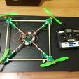
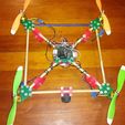
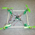
Everything went together easily and smoothly with only a few minor exceptions. Since I could only get M3 screws locally in one length (10mm), all of the motor mount screws had to be through only the top part of each vertex (missing 1 hole on 1 in each vertex). The rods give you a substantial amount of play in how square the frame comes out. The screws in the outer vertexes shake themselves out and need to be installed tightly. The center piece on mine has loose screws and is holding together fine. Use Velcro to hold the ESCs onto their tabs on the center and for receiver mounting on the bottom. My battery is mounted in a bit of a clunky way. I have a piece of cardboard with holes punched for the screws and nuts hot glue to the bottom with Velcro on it. When installing the legs you will want to soften them with a heat gun and add a touch of hot glue to prevent them from rotating.
Step 6: Check motor directions and install props
One by one connect each ESC to the throttle channel of the receiver and see which direction it spins. A piece of tape on the shaft makes it easier to see. Since you probably clipped the center wire out of 3 of them, you will need to connect the one with the power wire to some other channel on the receiver while testing those 3. Consult the diagram in the above pdf for the desired direction of each motor. On any that spin the other way switch any two of the three wires going to the motor. This is a fine time to connect the correct prop to each motor.
Step 7: Install and configure the MultiWii Board
Screw the MultiWii board to the standoffs using sheet metal or similar screws. You may want to drill down the guide holes to get a better fit depending on how it printed. Snap the standoffs into their holes. If it’s a loose fit use a drop of hot glue to hold them down. Connect the receiver to the MultiWii board as directed in the pdfs above; I wouldn’t bother with the ESCs yet. Connect the board to your computer and run the configuration software. You will want to check that each of your control sticks is going over a correct range and has a correct center point. Use the trim settings or the software in the radio to adjust if required. I also turned down the sensitivity to around 1/3 of its default value (as detailed in the pdf) and it still feels too sensitive to me. You should also put it on a level surface and use the calibration tools.
Note: You will want to use AUX1 even though the package did not contain enough wire to hook it up. AUX1 is used to toggle stable mode which you will probably want to use. DO NOT SKIP AUX1.
DO NOT SKIP AUX1.
Step 8: Test fly
Connect all wires to the board as directed in the pdf. I highly suggest you tether it so that it can’t really move or get more than a foot or so up. My first flight had the throttle sensitivity way out of whack and the quad shot up way out of control. Look at the stick commands in the pdf. You will notice that just turning the throttle up will NOT start the motors. You should use the stick based calibration commands too. In this flight you will be mostly looking at control sensitivity, accuracy of your calibration, and most importantly inverted axis in your controls. You should now be tuned well enough to fly and more tuning is out of scope here.
TL;DR It’s easy. Just go for it.

/https://fbi.cults3d.com/uploaders/19419862/illustration-file/9ab8d844-926f-4a17-9668-4650648a13c0/IMG_20120629_142815_display_large.jpg)
