Youtube video:
https://youtu.be/TWOMCni3EWI
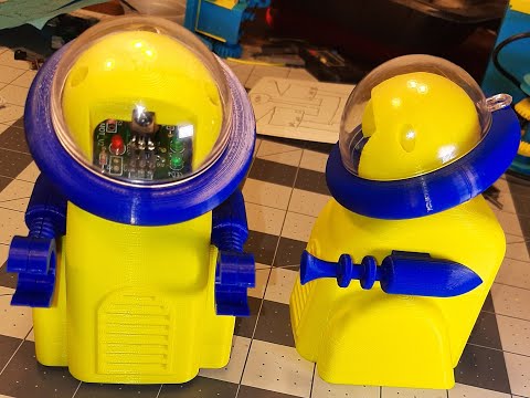
This 3d printed project is another remote controlled toy robot that is driven by a single motor. It can move forward or spin in place. It uses a two way to one way rotation mechanism to accomplish this. It has 2 control options. You can control it with 2 SPDT switches or use the IR control board I designed.The motor is an N20 gear motor. The battery is a 3 AAA battery pack or you could use a single cell lipo. The remote control is a universal infrared remote unit set up to transmit 12 bit Sony codes. The ir commands are interpreted by a microcontroller and drive the motor through a L9110s motor driver. For this project the right angle headers are not soldered to the top of the board. The 2 pin right angle header for the motor is soldered on the bottom of the board and bend slightly. The power connection for the board is a short pigtail soldered directly to the board with male Dupont connectors. The battery has female headers pins soldered to it.
There are two versions of the mcu board. One uses an Attiny85 and the other uses a Picaxe 08M2. I used to do a lot with the Picaxe and it's a nice fit for this project. It's Basic language is less intimidating than the Arduino C++ language. It also contains built in commands for reading Sony ir codes. I will include links to the EasyEda schematics and boards for both versions. You can order the boards through JCLPCB, PCBWay, or any place you choose. I got 5 of each board from JCLPCB for a under 20 dollars. You just have to watch which shipping method you pick. The only surface mount component on the boards is the L9110s but it's it can be easily hand soldered. The resistors are all 1/8 Watt. The gerber files for having the boards manufactured will be on the Github for either the Picaxe ar Attiny board.You will need to zip them up to send them to the pcb manufacturer. You can also open the project in EasyEda and get the zip files from there.
You will need some special hardware for the build. The 57 mm brass shafts is cut from 1/8 inch rod but 3MM should work. I used 1/8 inch brass welding rod from a Tractor Supply. The screws are 3MMX8MM and 2MMX8MM self tapping screws. I got them off Ebay. Some double sided tape for mounting the battery box. Super glue. A 3mm or 1/8 inch drill. O rings for tires. I got the O rings in an O ring kit from Harbor Freight. The inside diameter is approximately 30 mm. Some female Dupont connectors to connect the battery and the motor to the controller board.
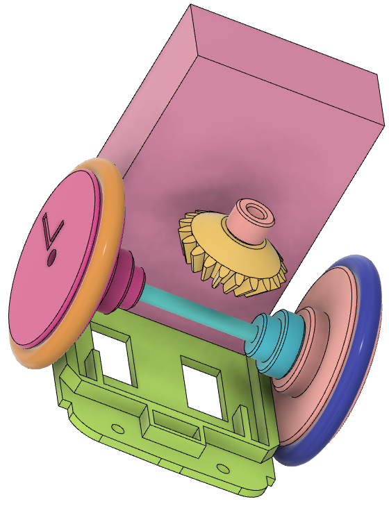
The most difficult part of the assembly is the ratchet axle mechanism. The 57 MM 1/8 inch brass rod is mounted permanently to the right wheel. I pressed it on with a drill press for exact alignment but I've also made one by tapping it in with a hammer. Just be careful to get it straight.
The right_bevel_gear and right_gear_spacer are mounted permanently to each other by tapping them together with a hammer using the 3D printed arbor.
The left_gear_spacer_wheel and left_bevel_gear are also joined permanently using the hammer and arbor.
You may have to do some adjusting with files and sandpaper if the parts are too tight to fit together. If they are too loose for the press fit you can use super glue. You can also try adjusting slicer settings to get a better fit.
After you get the right bevel gear and left wheel assemblies complete you need to drill them out with an 1/8 inch drill so that the brass axle spins freely inside them. I used a cordless drill. Make sure you get the drill started straight. You could also use a drill press.
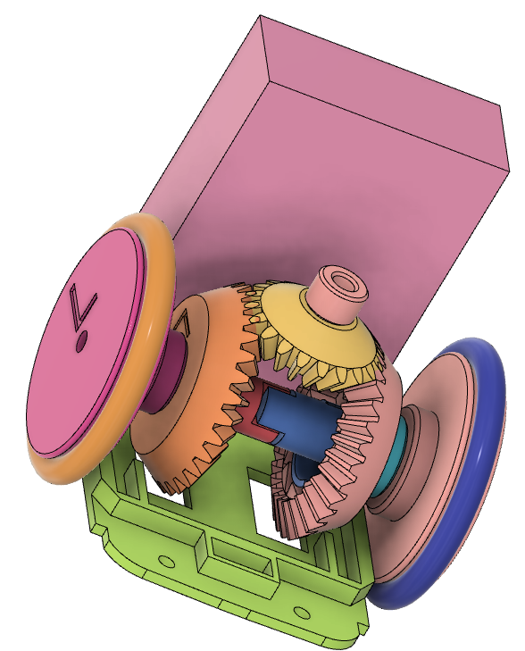
The left_ratchet and right_ratchet will probably need to be drilled out for ease of assembly. Try to drill them out just enough to allow them to be slid onto the axle and their positions adjusted. The axle will attached to these parts (the ratchets) permanently with super glue after they are in their final position. Be careful when holding them to drill. It's easy to break or crack the little fingers.
Slide the right wheel and axle through the right_bevel_gear assembly. The bevel gear should spin freely on the axle without a lot of wobble. Then slide the right ratchet onto the axle. Next is the left ratchet. The notches on the ratchets interlock. The ratchets do not have to spin freely. Next slide the left wheel bevel gear assembly onto the axle. It should spin freely.
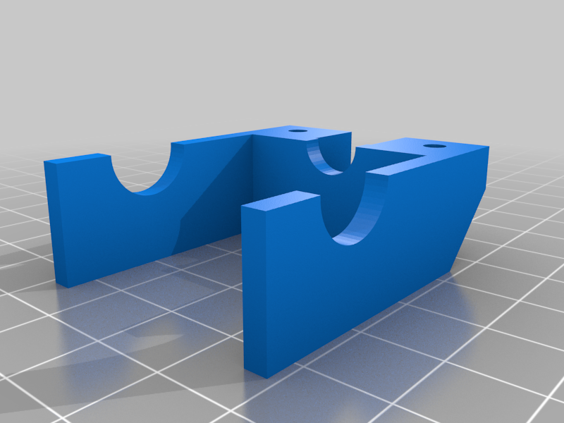
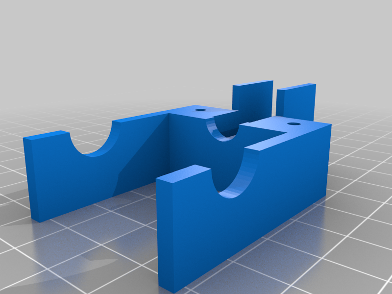
Super glue the castor plate to the frame. The frame is the smaller of the frame components. It has sacrificial bridges in the screw holes you need to drill out. The castor plate has locating rails to position it.
After the glue is set you can put the entire wheels-axle-ratchet assembly into the frame. The left wheel goes on the left side with the switch pocket on the castor plate facing you. Now you can mount the frame clamp with 2 3MM X 12MM screws. This should hold the axle assembly in place. Do any final adjusting, filing or sanding so that everything spins freely. Now you can super glue the ratchets to the axle. Be careful not to use too much glue and glue the bevel gears to the ratchets.
The N20 motor is positioned in place with the top bevel gear so that everything runs freely. Then the motor is hot glued in place. There is a spacer between the motor and the bevel gear. Hook up the motor to a battery box and run it forward and reverse. When the motor is run forward both wheels should spin in the same direction ( move the bot forward). When the motor is run in reverse the left wheel should run in reverse and the right wheel should still run forward ( spin the bot in place ).
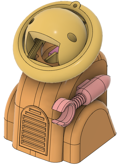
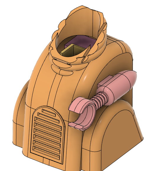
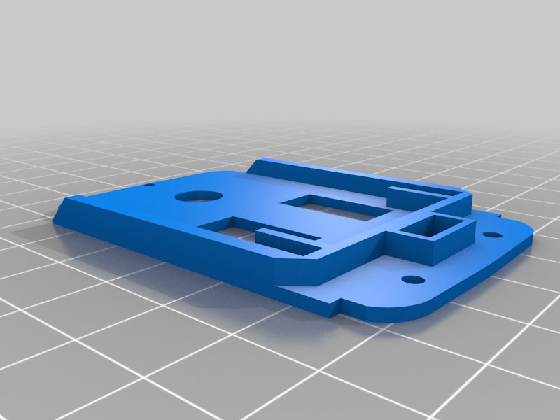
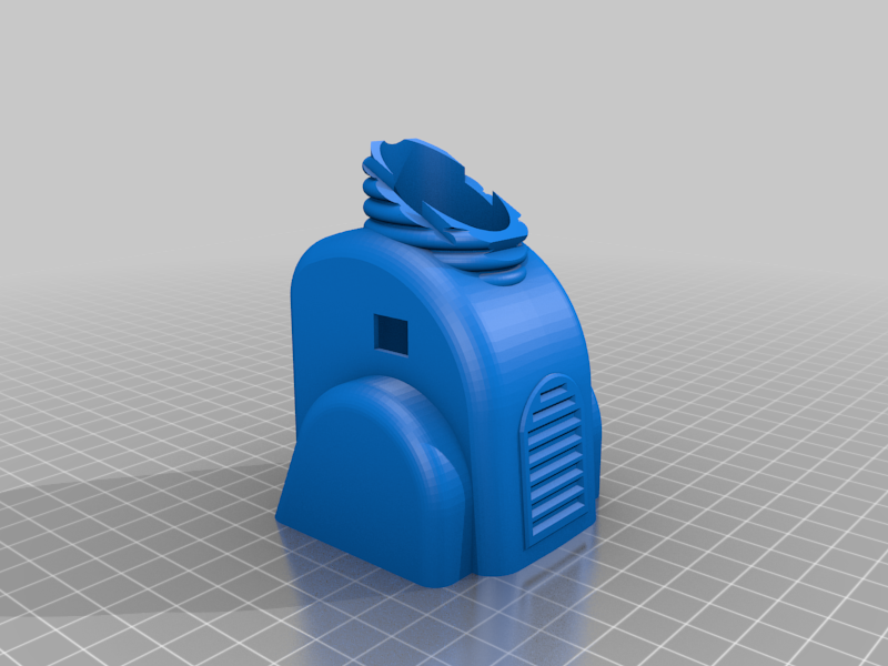
At this point the rest of the assembly is pretty self explanatory. The head is super glued to the body. The inner_globe is used to clamp the pcb in place with two 2MMX8MM screws. The body is screwed to the castor plate with three 2MMX8MM screws. The clear globe is a 50mm Christmas tree ornament. It is held to the head with a 3MM X 8 MM screw. The bottom of the battery box is mounted to the castor plate with double sided tape.
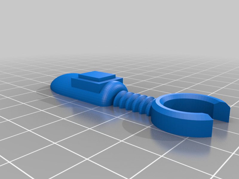
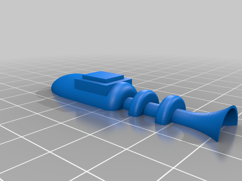
You can mount either an arm or a lazer blaster to the body. I've included both in the files. They are made in 2 parts and have to be glued together. Each half has 2 holes for 1.75 MM filament for alignment during gluing.
3D printing notes:
Any files with an X2 or X3 require 2 or 3 of the parts.
The file body.stl has to be printed with supports.
The files right_ratchet and left_ratchet.stl have to be printed with 100% infill.
Links:
Github Wiki for Picaxe code and pcb files:
https://github.com/Rick-100/Single-motor-3-function-toy-robot-Picxae-08M2-version/wiki
Use the file IR_motor_for_rev.bas for programming the 08M2.
Github Wiki for Attiny85 code and pcb files:
https://github.com/Rick-100/Single-motor-3-function-toy-robot-ATTINY85-version/wiki
Use the file attiny85_sony_ir_basic_pwm.ino or attiny85_sony_ir_basic_pwm.hex for programming the attiny85.
EasyEda Picaxe schematic and board:
https://easyeda.com/Rick100/ir_picaxe
EasyEda Attiny85 schematic and board:
https://easyeda.com/Rick100/attiny85-ir_motor_copy
50MM Clear globe:
https://www.ebay.com/itm/123380692966?hash=item1cba0ff7e6:g:n~cAAOSwN~Zbo2sh
description:
DIY Clear Balls Baubles Sphere Fillable Plastic Christmas Tree Ornaments
Battery box :
link:
https://www.ebay.com/itm/174797750980?hash=item28b2c202c4:g:A0EAAOSwuZFhz2ci
description:
2x 3-AAA Slots Battery Spring Clip 4.5V Holder Case Plastic Storage Box + Wires
Screws 5 ea:
M2 X 8
link:
https://www.ebay.com/itm/373694873117?hash=item5701f33e1d:g:7usAAOSw5wJcIFJg
description:
M2 Black Steel Phillips Round Pan Head Self Tapping Screw Sheet Metal Wood Screw
M3 X 12 screws 2 ea
For switch control
Roller switch 2 ea:
link:
https://www.ebay.com/itm/203746073302?hash=item2f70365ad6:g:9EwAAOSwWLphsfJ4
description:
10pcs Mini Micro Limit Switch Lever Arm SPDT Snap Action Momentary Roller
:format(webp)/https://fbi.cults3d.com/uploaders/17518409/illustration-file/df78873f-09b5-49f3-a405-faa25ed509bb/20220315_224342_2-min.jpg)


/https://preview3d-images.cults3d.com/variants/hn6z35z9849v7a832f34l6c4pby8/0efb2e1d82dc631f5d34681a1ec0e058e5293ebb996af2b22972af828007c8d8)
/https://preview3d-images.cults3d.com/hk3hysjwou4u9xg4bc31b8cm96n8)
/https://preview3d-images.cults3d.com/variants/3z6rmapm07kmft4aks0r77fvp815/0efb2e1d82dc631f5d34681a1ec0e058e5293ebb996af2b22972af828007c8d8)
/https://preview3d-images.cults3d.com/variants/9x3epdqc354rxb9kbvc8za24ox1n/0efb2e1d82dc631f5d34681a1ec0e058e5293ebb996af2b22972af828007c8d8)
/https://preview3d-images.cults3d.com/variants/lzrur0lh9twrm1hidfr9k54zv2it/0efb2e1d82dc631f5d34681a1ec0e058e5293ebb996af2b22972af828007c8d8)
/https://preview3d-images.cults3d.com/variants/au5fyhaw8c8tsff1wdeir601qilp/0efb2e1d82dc631f5d34681a1ec0e058e5293ebb996af2b22972af828007c8d8)
/https://preview3d-images.cults3d.com/variants/wa30uymr0v4fvklx2mdc7jc954r7/0efb2e1d82dc631f5d34681a1ec0e058e5293ebb996af2b22972af828007c8d8)
/https://preview3d-images.cults3d.com/variants/cz7u7go6ym6nctuhen6vpwre4i9k/0efb2e1d82dc631f5d34681a1ec0e058e5293ebb996af2b22972af828007c8d8)
/https://preview3d-images.cults3d.com/b5itdydclz2uzgawwuu6ot3vpa4g)
/https://preview3d-images.cults3d.com/variants/25mnbbtjq5c64kj4rt2oqr4b8lpy/0efb2e1d82dc631f5d34681a1ec0e058e5293ebb996af2b22972af828007c8d8)
/https://preview3d-images.cults3d.com/variants/saq25pa98vce9z8dhw1lralnjdrk/0efb2e1d82dc631f5d34681a1ec0e058e5293ebb996af2b22972af828007c8d8)
/https://preview3d-images.cults3d.com/variants/0kjl9971hl6a11rs3noxa22u6utz/0efb2e1d82dc631f5d34681a1ec0e058e5293ebb996af2b22972af828007c8d8)
/https://preview3d-images.cults3d.com/variants/3az9ics0iiq7961m113qthayrafw/0efb2e1d82dc631f5d34681a1ec0e058e5293ebb996af2b22972af828007c8d8)
/https://preview3d-images.cults3d.com/variants/4z4g6658pwmm1dud2potjxg0fpbb/0efb2e1d82dc631f5d34681a1ec0e058e5293ebb996af2b22972af828007c8d8)
/https://preview3d-images.cults3d.com/variants/qwmrta0lzinfjymgkq2m10wi9m9w/0efb2e1d82dc631f5d34681a1ec0e058e5293ebb996af2b22972af828007c8d8)
/https://preview3d-images.cults3d.com/variants/mmsfd25x0njxu4bxowamqsjk3sn6/0efb2e1d82dc631f5d34681a1ec0e058e5293ebb996af2b22972af828007c8d8)
/https://preview3d-images.cults3d.com/variants/c2ls9y97o6cutqq5eugpxpvt8zor/0efb2e1d82dc631f5d34681a1ec0e058e5293ebb996af2b22972af828007c8d8)
/https://preview3d-images.cults3d.com/variants/2pink4ng9d6zp91qawa4xk8l8etb/0efb2e1d82dc631f5d34681a1ec0e058e5293ebb996af2b22972af828007c8d8)
/https://preview3d-images.cults3d.com/variants/c4b8q9yzs8l4b7zvr45hkvqpj1qk/0efb2e1d82dc631f5d34681a1ec0e058e5293ebb996af2b22972af828007c8d8)
/https://preview3d-images.cults3d.com/variants/ykuupblhmw10worl6n371akx78s5/0efb2e1d82dc631f5d34681a1ec0e058e5293ebb996af2b22972af828007c8d8)
/https://preview3d-images.cults3d.com/variants/mbke975mio427uwld5ypgzarjr90/0efb2e1d82dc631f5d34681a1ec0e058e5293ebb996af2b22972af828007c8d8)


