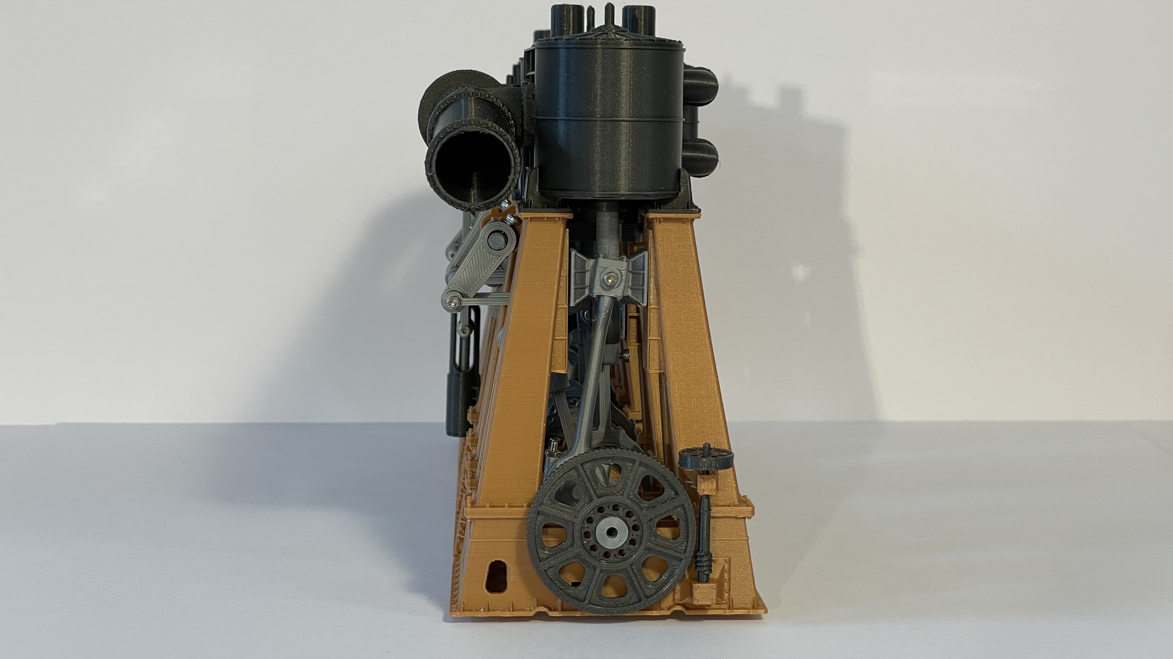
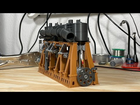
This engine is the one on the right side of the ship (starboard).
The front of the engine is where the (optional) crankshaft will be attached.
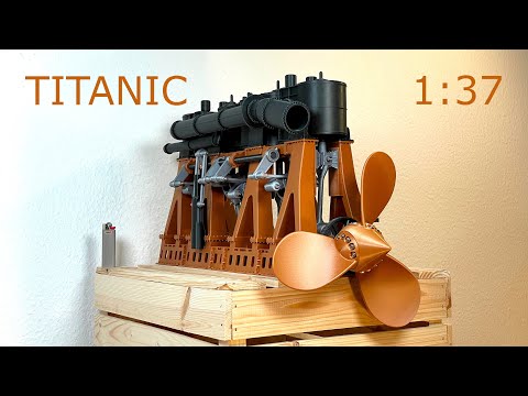
The back of the engine is where the flywheel will get attached.
HP stands for high pressure and refers to the second cylinder counting from front to back.
IP stands for intermediate pressure and refers to the third cylinder counting from front to back.
LP stands for low pressure and refers to the first and last cylinder.
Everything prints best at 0.2 mm height.
For the legs, make sure to block supports inside the base since it will be difficult to remove. Also make sure that bridging is set to a 45 degree angle such that the bridging distance is not too big at any point.
For the cylinders, make sure they are printed upside down. They have a small lip that is broken up on the lower side to ensure it fits with the lower covers. They should be up in the air. Use ironing on the top surfaces of the cylinders to make them smooth. They will print without support.
For the lower covers, paint on the support in the middle to avoid support being placed on the inner lip and in the hole for the M2 nut. Make sure to add filament changes for the first layer that embeds the M2 nuts in the parts. Also note that the IP Lower has a lower layer covering the nut than the HP or the IP Lower covers.
The upper cylinder covers are meant to get glued together after printing. This is to avoid support material that would otherwise lead to an inferior fit. Glue the complete cylinder covers only to the cylinders when you are happy with how the engine runs. Additional sanding of the cylinder blocks is basically impossible once the top or lower covers are glued on.
For the crankshaft pieces, make sure they are all being printed in a vertical orientation, holes down to the print bed. Tell the slicer to align the seams to the rear to facilitate sanding. Note that the center pieces are a bit wider.
The rods are best printed standing upright using all supports.
The crossheads are printed in their natural orientation.
The cylinders and valves are all printed standing upright. You need to turn them 180 deg looking that they contact the bed with their wide side.
The IP to LP steam pipes are printed best with their flat side touching the print bed. This may feel unnatural because it uses more support material but this way, the bridging works much better in my experience.
The stephenson bridge is printed best with the plat side towards the print bed at an angle that the first layer of bridging is at a 45 deg angle.
1 x Base/Base Center Piece Left
1 x Base/Base Center Piece Right
0 x Base/Base Connection 2mm (Can be used instead of the 8mm for cleaner look, but less sturdy)
8 x Base/Base Connection 8mm
1 x Base/Base Inner Back
1 x Base/Base Inner Front (Note the small hole in the base for the steering pusher. You need to add some support here)
1 x Base/Base Outer Back
1 x Base/Base Outer Front
7 x Base/Crank Clamp Regular
1 x Base/Crank Clamp Wide (The last crankshaft bearing next to the flywheel gets the wide clamp)
1 x Base/Leg Connection BL
1 x Base/Leg Connection BR
1 x Base/Leg Connection CL
1 x Base/Leg Connection CR
1 x Base/Leg Connection FL
1 x Base/Leg Connection FR
4 x Crankshaft/Crank Rod
1 x Crankshaft/Crankshaft HP PT1
1 x Crankshaft/Crankshaft HP Section PT2
1 x Crankshaft/Crankshaft IP PT1
1 x Crankshaft/Crankshaft IP PT2
1 x Crankshaft/Crankshaft LP Back PT1
1 x Crankshaft/Crankshaft LP Back PT2
1 x Crankshaft/Crankshaft LP Front PT1
1 x Crankshaft/Crankshaft LP Front PT2
1 x Crankshaft/Crankshaft Middle Connection
1 x Crankshaft/Flywheel
1 x Crankshaft/Manual Crank Handle
1 x Crankshaft/Manual Crank
8 x Crankshaft/Spacer
1 x Cylinder Covers/Back Lower Cover (Add pause to insert M2 nut)
1 x Cylinder Covers/Front Lower Cover (Add pause to insert M2 nut)
1 x Cylinder Covers/HP Lower Cover (Add pause to insert M2 nut)
1 x Cylinder Covers/HP Upper Piston Cover Inner Part
1 x Cylinder Covers/HP Upper Piston Cover Upper Part
1 x Cylinder Covers/HP Upper Valve Cover Inner Part
1 x Cylinder Covers/HP Upper Valve Cover Upper Part
1 x Cylinder Covers/IP Lower Cover (Add pause to insert M2 nut)
1 x Cylinder Covers/IP Upper Piston Cover Inner Part
1 x Cylinder Covers/IP Upper Piston Cover Upper Part
2 x Cylinder Covers/IP Valve Upper Cover Inner Part
2 x Cylinder Covers/IP Valve Upper Cover Upper Part
2 x Cylinder Covers/LP Upper Piston Cover Inner Part
2 x Cylinder Covers/LP Upper Piston Cover Upper Part
4 x Cylinder Covers/LP Valve Upper Cover Inner Part
2 x Cylinder Covers/LP Valve Upper Cover Outer Part
1 x Cylinders/HP Cylinder (Print upside down)
1 x Cylinders/IP Cylinder (Print upside down)
1 x Cylinders/LP Back Cylinder (Print upside down)
1 x Cylinders/LP Front Cylinder (Print upside down)
2 x Eccentric Assembly/Cross Head Wide (The center legs are designed for the wider cross heads)
2 x Eccentric Assembly/Cross Head
4 x Eccentric Assembly/Rod Clamp (Print standing upright)
4 x Eccentric Assembly/Rod (Print standing upside down)
1 x Flywheel Turner/Flywheel Turner Handle
1 x Flywheel Turner/Flywheel Turner Lower Part (Print upside down)
1 x Flywheel Turner/Flywheel Turner Upper Part (Print two parts for additional cooling time)
1 x Helpers/Crankshaft Sanding Drum
2 x Helpers/HP Piston Sanding Drum
2 x Helpers/HP Valve Sanding Drum
2 x Helpers/IP Piston Sanding Drum
2 x Helpers/IP Test Pipe
2 x Helpers/IP Valve Sanding Drum
2 x Helpers/LP Piston Sanding Drum
2 x Helpers/LP Test Pipe
2 x Helpers/LP Valve Sanding Drum
1 x Helpers/Test Cover
1 x Helpers/Test Piece
1 x Pipes/Back Lower IP to LP Pipe (Print with the LP connection facing down)
1 x Pipes/Back Upper IP to LP Pipe (Print with the LP connection facing down)
1 x Pipes/Front Lower IP to LP Pipe (Print with the LP connection facing down)
1 x Pipes/Front Upper IP to LP Pipe (Print with the LP connection facing down)
1 x Pipes/HP Feed Pipe
1 x Pipes/HP to IP Pipe
1 x Pipes/LP Exhaust Pipe
1 x Pistons and Valves /HP Piston
1 x Pistons and Valves /HP Valve
1 x Pistons and Valves /IP Piston
2 x Pistons and Valves /IP Valve
1 x Pistons and Valves /IP Valves Adapter
1 x Pistons and Valves /LP Piston
4 x Pistons and Valves /LP Valve
2 x Pistons and Valves /LP Valves Connector
1 x Steering Pusher Arm Connector
1 x Steering/Steering Pusher Arm To Rod
2 x Steering Pusher Arm
1 x Steering/Steering Pusher Case
1 x Steering/Steering Pusher Inner Rod
1 x Steering/Steering Pusher Lower Cover
1 x Steering/Steering Pusher Side Rod
1 x Steering rod
4 x Step Linkage/Arm Connector
8 x Step Linkage/Eccentric Disk
8 x Step Linkage/Eccentric Rod
8 x Step Linkage/Steering Arm Connection 1_7mm hole
0 x Step Linkage/Steering Arm Connection 1_8mm hole (Can be used if 1_7 hole is too small)
0 x Step Linkage/Steering Arm Connection 2_1mm hole (Can be used if 1_8 hole is too small)
8 x Step Linkage/Step Link Axis Stopper
8 x Step Linkage/Step Link Axis
8 x Step Linkage/Step Link Bridge (Make sure bridging is as short as possible, align seams to corner of pin slot)
8 x Step Linkage/Step Link Hand
8 x Step Linkage/Step Link Spacer
4 x Step Linkage/Step Link Steering Arm
4 x Step Linkage/Step Link Valve Rod Adapter
:format(webp)/https://fbi.cults3d.com/uploaders/20967920/illustration-file/cbb3af7e-21fa-4738-acef-ec1c07ca86bf/SN2_2.gif)


/https://preview3d-images.cults3d.com/variants/o0ovaerd5dylc2ostgjdxcmncsoy/0efb2e1d82dc631f5d34681a1ec0e058e5293ebb996af2b22972af828007c8d8)
/https://preview3d-images.cults3d.com/variants/1x3llita6ly1wr4o1zifjlvhoycl/0efb2e1d82dc631f5d34681a1ec0e058e5293ebb996af2b22972af828007c8d8)
/https://preview3d-images.cults3d.com/variants/n8iwj26q3rpt3sr0332p6x5pi14o/0efb2e1d82dc631f5d34681a1ec0e058e5293ebb996af2b22972af828007c8d8)


