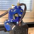
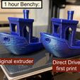
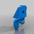
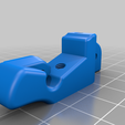
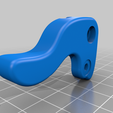
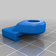
There are several Direct Drive mods available, but I wasn't satisfied with any of them. So I made one that preserves the full original print area. Even the full height can be preserved, but this would require a little thought in the cable routing and the filament spool holder.
Print each part in the orientation they are shown in the individual photos! And get your supports in order first, the models need a relatively precise and flat supported surfaces.
The modification uses many parts from the original setup, but the PTFE tube must be cut, making this a non-reversable mod (unless you have a spare tube).
The photos in this guide can be clicked to full size.
If you really like this mod, I am extremely grateful even for the tiniest of donations! All cool if that's not your style though.
You also need 4 additional screws:
- M4 x 16 mm counter-sunk / flat top
- 2x M3 x 20 mm pan/round head
- M3 x 10 mm pan/round head
And:
- M4 locking nut
- Stepper motor extension cable (can temporarily print without the extension)
ASSEMBLY
- Remove your currently installed filament, if any, and detach the PTFE tube from the extruder.
- Remove the extruder motor. Take note where each screw used to be.
- Remove the hot end's fan cage with the single screw between the wheels.
- Remove the hot end.
FRAME
- Remove the top two wheels from the X-axis sledge.
- Position the printed Frame in place and install the bolts and wheels back on through the Frame. The bolts should be just barely long enough. Make them taut.
- Place the extruder on the Frame with the connector upwards, and use one of the original pan head screws and a printed washer to mount it from the top left hole. Leave the screw loose.
FRONT
- Install the original spring tension screw assembly from the original extruder. Check the photos for orientation.
- Mount the Front on the Frame using the original hot end mounting screws. The screws go in the two bottom holes of the extruder motor. Leave the screws loose.
LEVER
- Install the original filament roller in the back side indent of the printed Lever with a M4 x 16mm countersunk screw. Secure the screw with the locking nut. Make sure the roller spins freely.
- Use the mounting screw and the small bracket it sits in from the original lever. While holding the spring in it's place, install the Lever on the Frame through a printed washer. Leave the screw loose.
- Make sure the extruder motor sits all the way in it's slot, and tighten the four motor screws little by little.
- Using the smallest 1.5mm allen wrench provided with the printer, reposition the extruder gear to align with the wheel on the Lever and not to touch the printed Frame.
- Tighten the Lever's spring so that the filament wheel sits semi-taut against the gear.
HOT END
- Position the hot end in it's place, and mark up the tube 2mm below where it reaches the top of the Front part.
- Cut the tube straight at the marked spot. Make sure to get a clean and flat cut! A Bowden tube cutting tool is recommended but not necessary.
- Position the remaining tube that sits in the hot end into the hole at the bottom of the Front part.
- Push the hot end up as high as it gets. Measure how far below the mounting holes the hot end remains (mid hole to mid hole).
- Further cut the PTFE tube that sits in the hot end for the amount you just measured.
- Install the hot end in place using the new M3 x 20mm screws. Hold the hot end up straight while you screw it in quite taut.
- Install the fan cage in place using the new M3 x 10mm pan head screw from behind.
FILAMENT BRACKET
- Remove the PTFE tube socket from the original extruder bracket and install it on the printed Filament Bracket (on the opposite side to the square bracket).
- Cut an approximately 3" long piece out of the remaining PTFE tube, and push it all the way in the tube socket.
- Snap the printed Filament Bracket in place on top of the Frame.
Done! Besides leveling the bed there's only one thing to do:
REVERSE THE EXTRUDER'S DIRECTION FROM THE PRINTER SETTINGS!!!
If the original firmware doesn't support this, install Mriscoc's magnificent Marlin firmware!
========================================

/https://fbi.cults3d.com/uploaders/29035273/illustration-file/3e0950c8-cc5e-4958-b384-60b5988bdf90/f6c10ec5-862c-46f4-8469-dfa367dd4201.jpg)
