PURPOSE
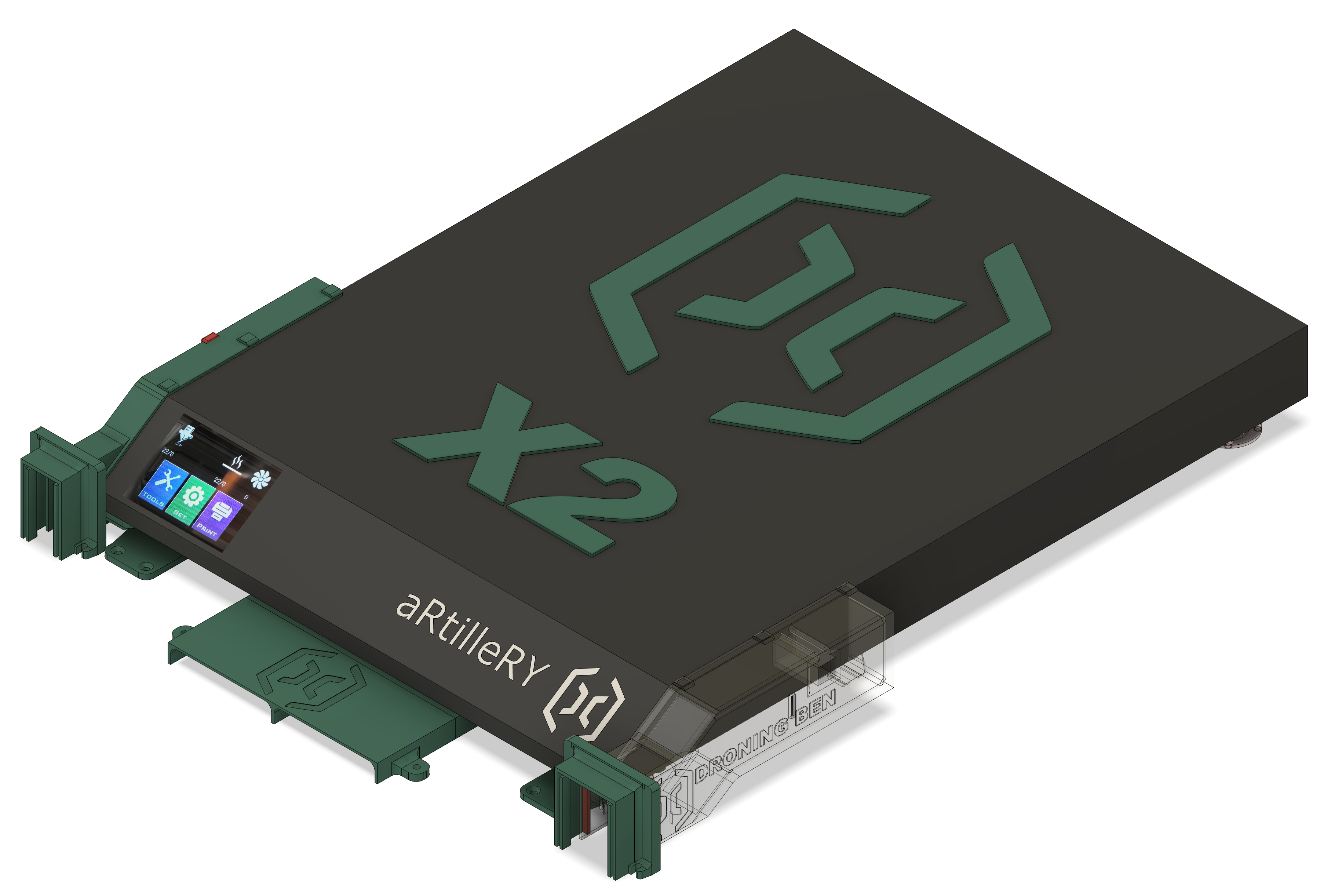
In order to print objects using special materials requiring hot temperatures (Nylon, ABS…), I built a box for my SW X2.
However, I didn’t want the CPU’s air cooling system to take hot air from the inside of the box.
I didn’t want the air coming from the outside to bring dust into the box either.
So I designed air intake ducts to be attached to the sides of the printer, and an outlet to be underneath (where the big fan is); they all go through the front door of the box.
At the same time, I wanted to put the printer on dampers, to avoid transmitting vibrations to the board (and so to the wooden wall…) when stepper motors shake the printer (printing zebras…).
Then, I had to figure out how to connect the moveable ducts (attached to the printer) to the ducts attached to the board (the ones going through the front door of the box).
So, I created gates (porch + sliding door); then the front part of the ducts attached to the printer can move forward&backward through the doors, and at the same time (when the printer swings right-left), the doors can slide into their porches (4mm max each sideways). This way, no hot air coming from the box can be sucked out by the intake ducts.
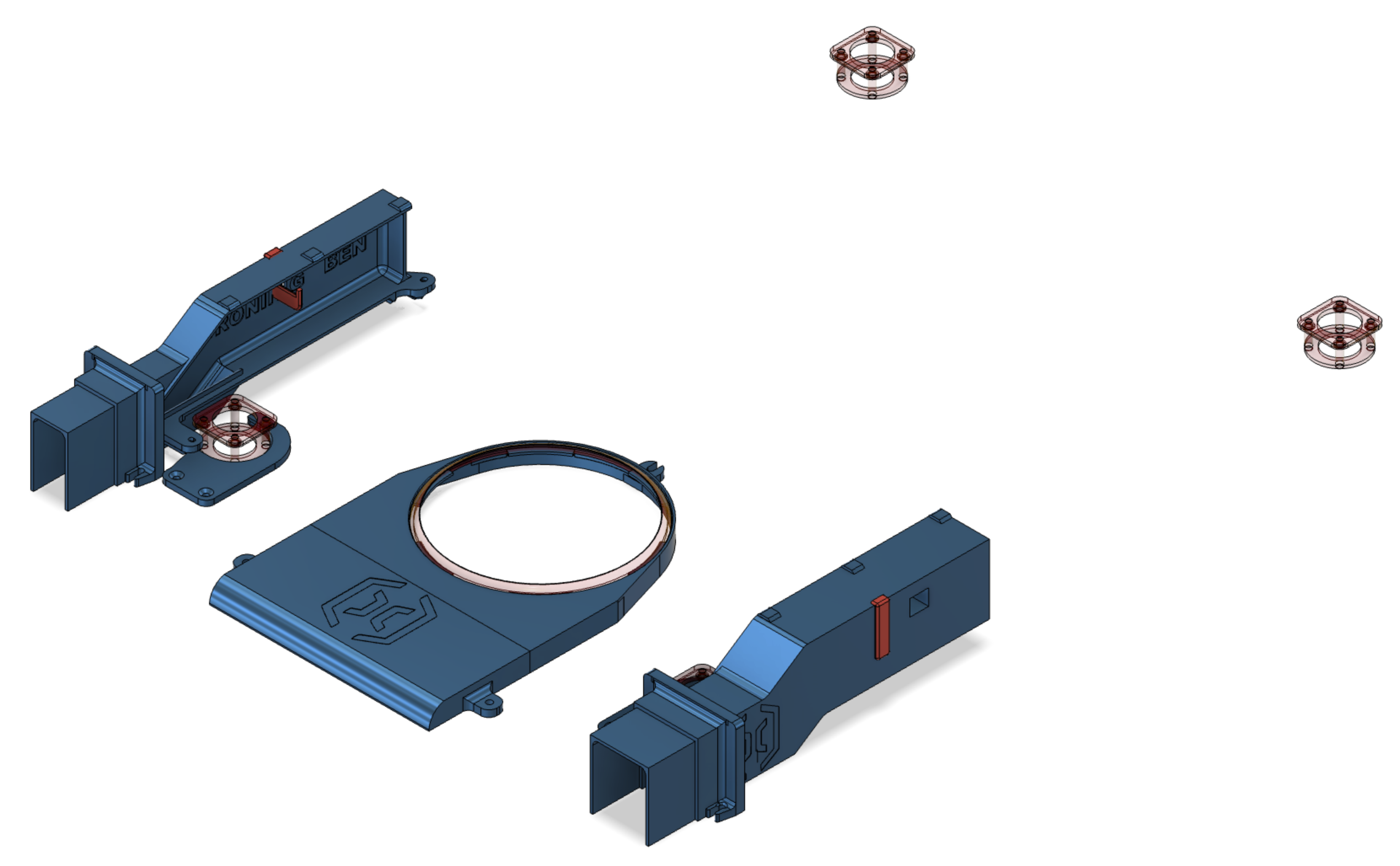
PARTS DESCRIPTIONS
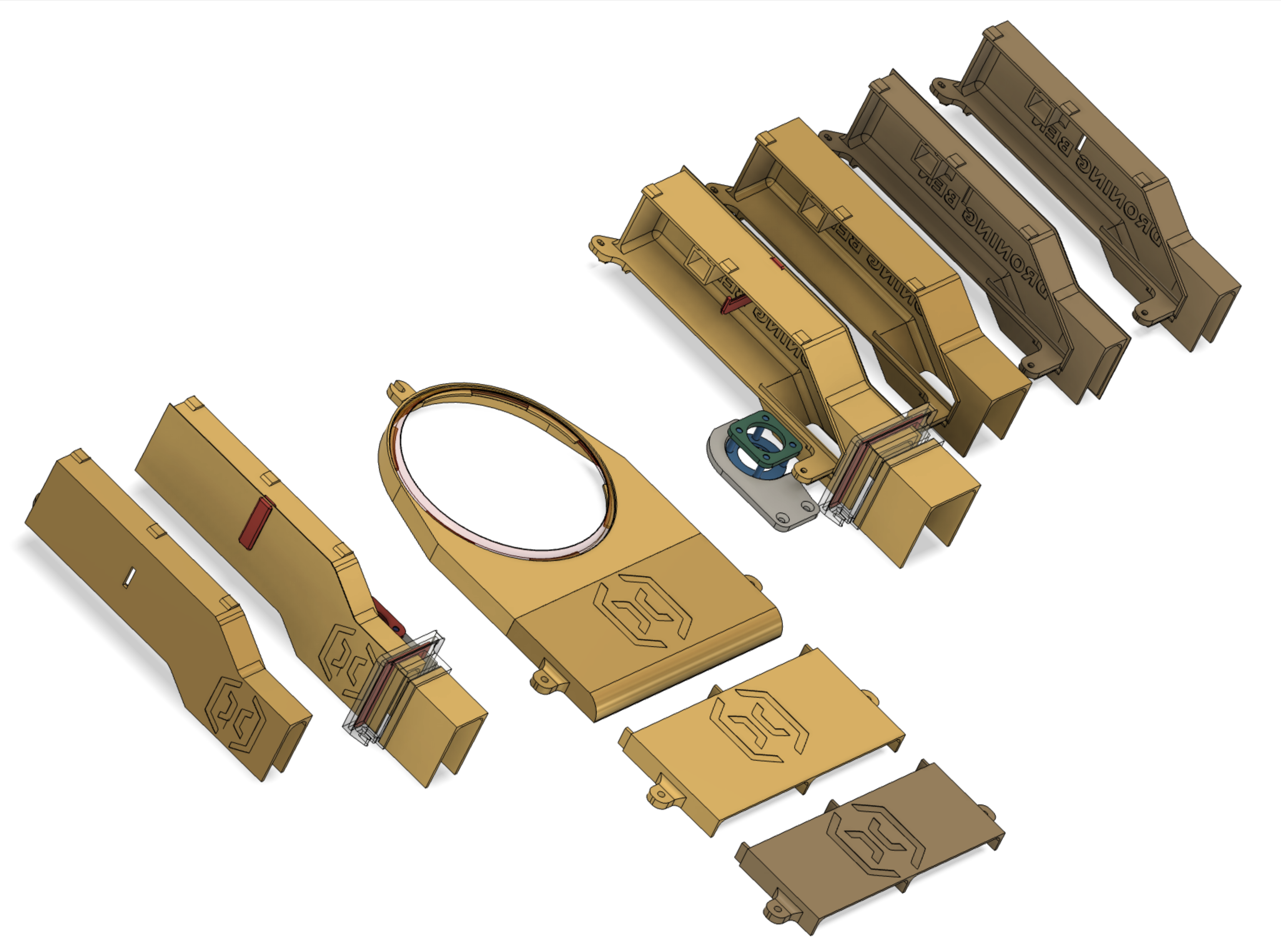
A, B & C - Parts attached (or touching) to the working board
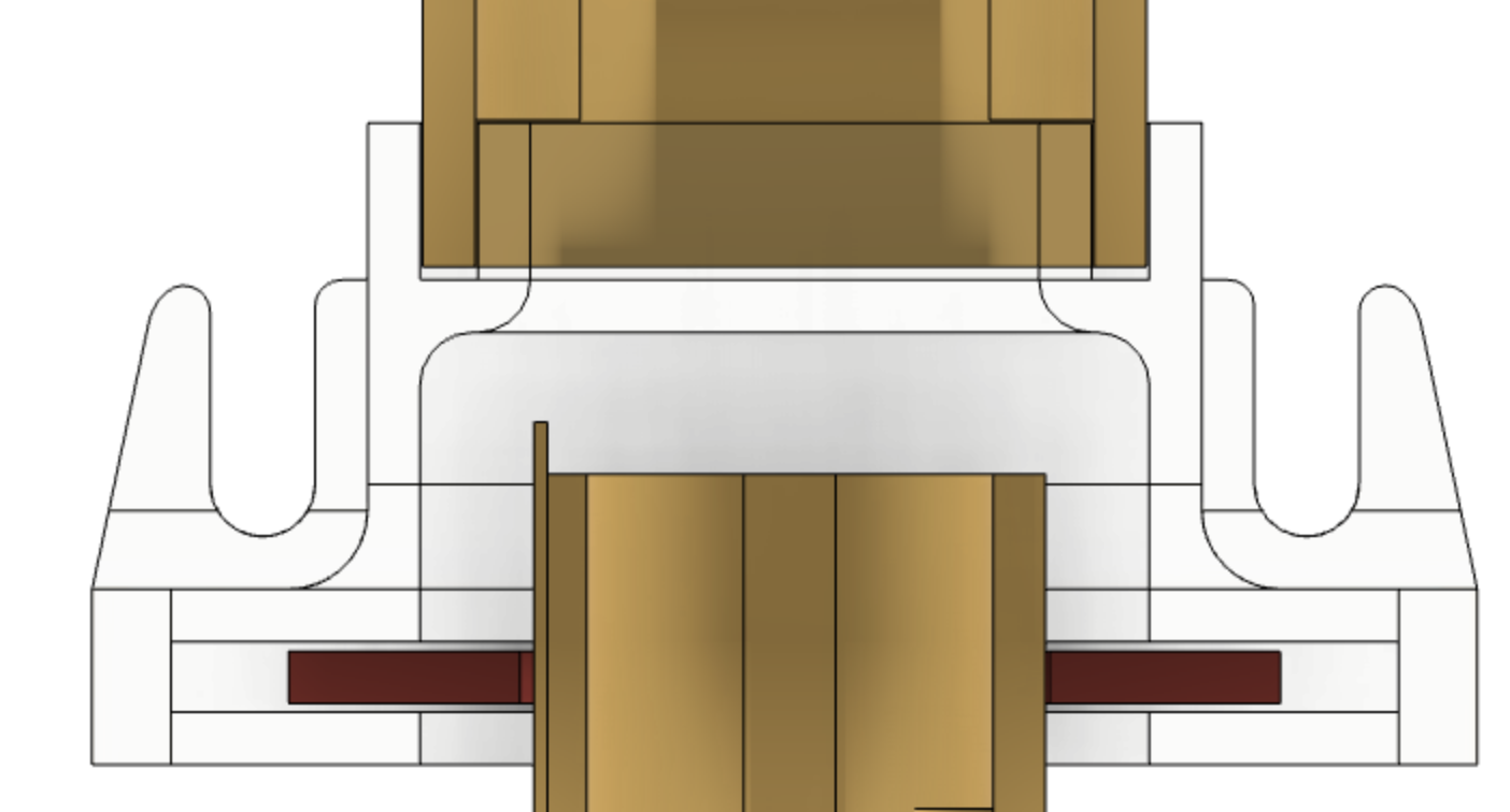
A - Foot dampers
Their base is composed of 4 columns attached to a bottom ring; columns have to be plugged into a top ring that goes around printer’s foot. I recommend to print all using soft TPU.
I tried to find the appropriate ring diameter to keep the damper staying around the foot, but the feet are conical & made out of a slippery plastic (> use double face tape).
To avoid the printer from changing position when swinging, because the printer’s ducts have to stay aligned with the ducts attached to the board, you have to use a minimum of 2 hooks (to hold the front feet; see screen copies).
B - Gates
A gate is composed of a porch, a door, and an optional extension.
Depending on the distance between the front of the printer and the front door of your box, you may have to use of the porch extension (34mm); if the extension is too short, you can extend it with your slicing software (cheating with X or Y axis), if it is too long, cheat with Z, putting the bottom of the part lower the printing bed.
Case B2:
If the distance between the front of the printer and the front door of your box is 20mm, you can even avoid using gates, if you agree to have a 4mm gap each side of the printer’s ducts (because they go through the front door without using sliding doors).
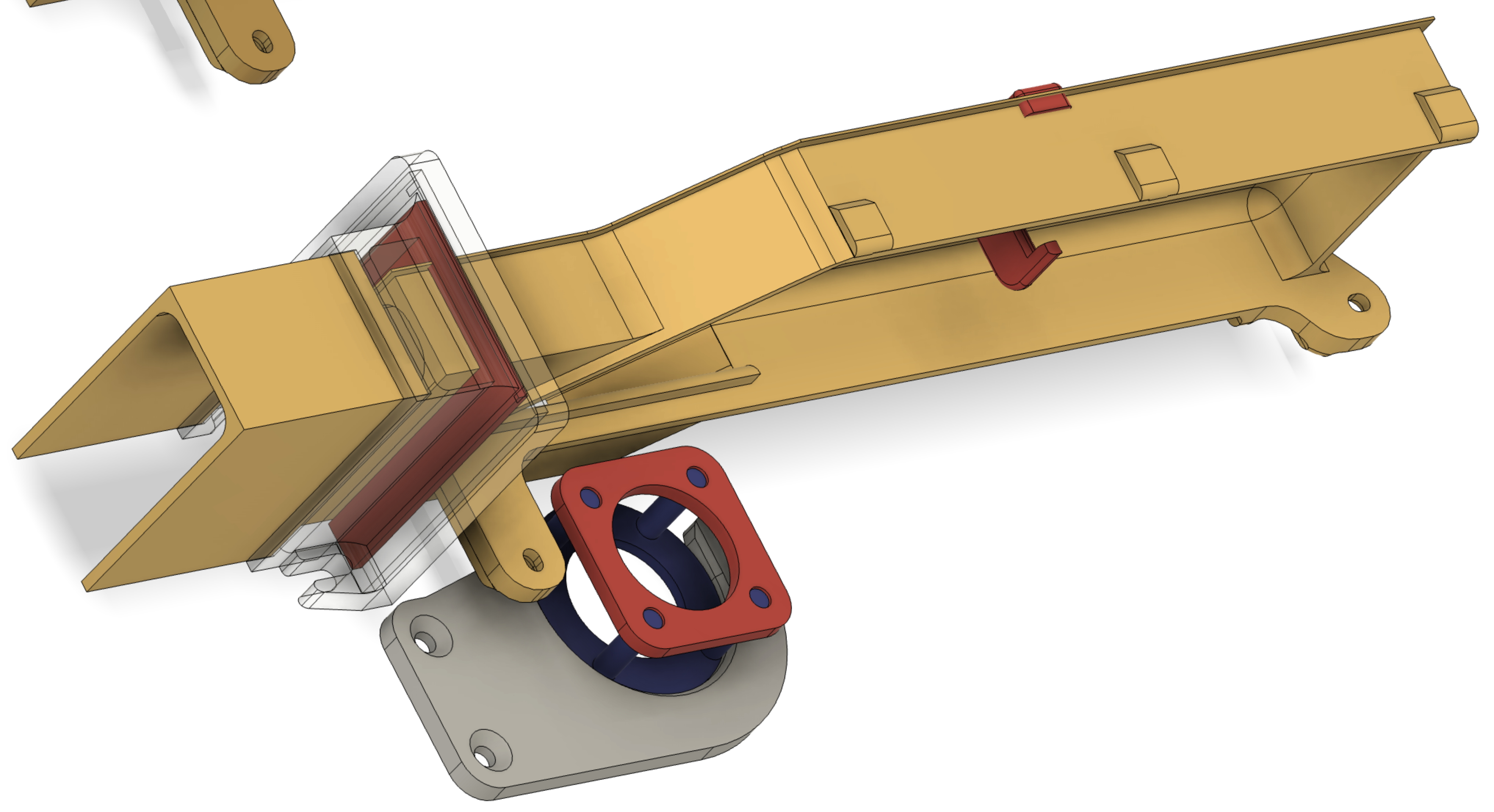
C - Outlet duct
The air used to cool down the electronic parts is blown out by a big fan attached to the bottom face of the CPU box.
If you are up for making a big hole into your working board, use the "c13 - Seal-ring" support; if you prefer to reject the « hot » air toward the front, print the other outlet system.
The outlet duct isn’t attached to the printer but to the board; there is a seal (ring) rubbing onto the bottom face.
The seal (to be printed in soft TPU) is held by a riser connected to a front extension; I’m providing a few (different lengths) including one with a curved end (designed this way because my printer is venting at my back) & a (20mm) XS one (see the B2 case above).
D - Parts attached to the printer
Let's talk about the main ducts now (intakes).
Based on the numbers (& width) of the grooves the fresh air is sucked through, I did calculate for each side what the cross-section the ducts must be. As I wanted my ducts to clip the CPU box, I came to design a « full height x 21mm » duct for the right side (side of the touch screen) & a « full height x 37mm » one for the left side.
Nb1: despite the fact there are more grooves to the left, a 21mm duct should do the job for this side because the air flow isn’t that important ; that’s why I’m providing the left duct in 2 widths.
Nb2: "L" little clips help to keep the ducts tight onto the CPU sides, grabbing the sides by groves.
Nb3: print the left duct using transparent material if you want to see the blue inside light flashing through the grooves when printing in the dark.
Printing/designing techniques:
1) You may have noticed that I’m providing 6 printer ducts in total (2 times each one of the 3 discussed above).
That’s because I want you to be free to embrace or not my printing techniques.
I had (on my own) this idea after watching the way the slicer & the X2 printer work.
Recently, after watching a Maker’s Muse YouTube video about 3D printing tricks (https://youtu.be/9-6tIkTrcwA), I’ve been able to put a name onto my wall printing technique : sacrificial wall.
Problem: the slicer tells the printer (for each layer) to print walls first then to print the lines of the layer within the inside wall, so each thread (line) of the layer is only touching the wall by its ends.
My solution: it seemed to me that the bottom face of a print may be more solid with walls printed onto the a layer being the full size of the bottom face. So, after my design is achieved, I add a 0.6mm thick brim (to be cut) to the bottom face (2 layers based on my CURA’s settings) and 2mm wide (sides thickness of my ducts). So, after the first 2 layers have been printed, the walls are printed on the edges of the enclosed lines of the bottom face.
Nb: I close holes of the bottom face with sacrificial layers as well (you have to open them using a cutter or a hot rod), because the printer starts making walls around holes, and sometimes they are so small rings that they don’t take the bed.
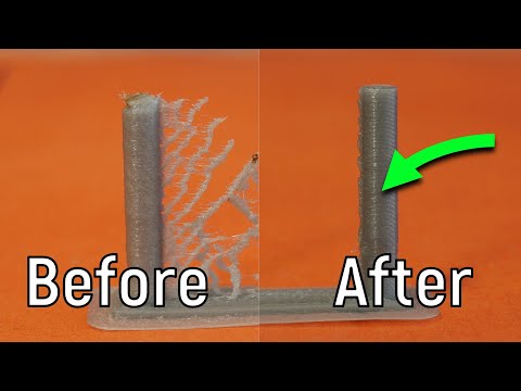
2) Easing supports removing
Bottom part of the ducts (close to the board) don’t have a floor (use duct tape - LOL - to make the missing bottom floors), because it wouldn’t be possible to remove supports pulling them from the front only. It’s useful as well to have less support to remove as possible. Have a look at the screen copies to see how better it is to use tree type supports linked to a high angle (70°).
It's long work to print all the parts, but your X2 station will look so neat.
Floss your teeth!