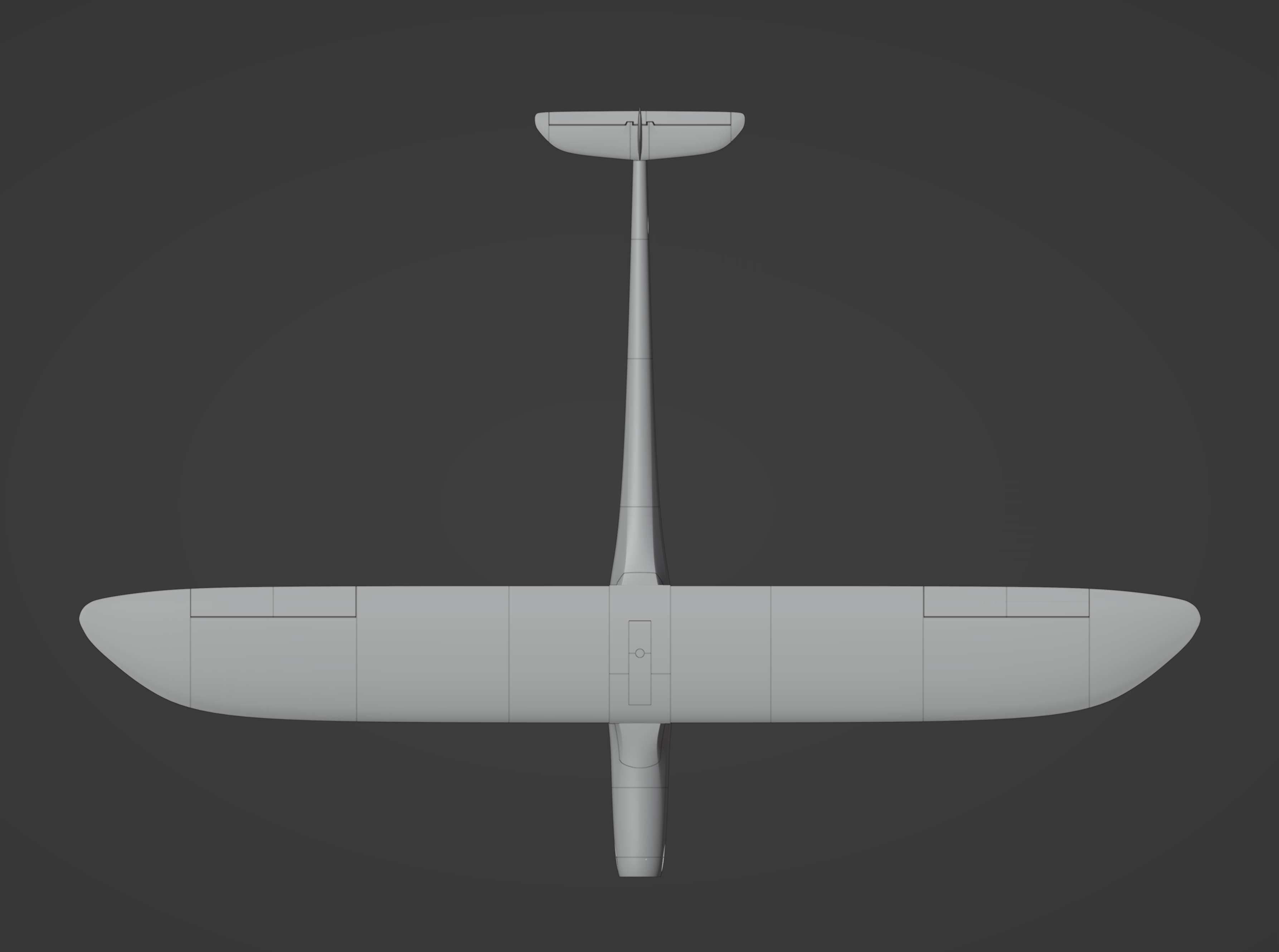
Specs
Wing span: 1200mm
Length: 800mm
AUW:
720g with 3s 2200mah emaxx 2205 2600kv
CG: 29mm from leading edge.
Test flight video(s)
3s maiden: https://www.youtube.com/watch?v=BHo26XKOryk
Link to files: https://cults3d.com/:1309085
Want this plane for free?
If you are so inclined you can get the this model for free by doing one of the following:
- Provide a flight video
- Provide build video
- Provide an overview of the process from build through flight.
Doing just one of the following and submitting for review, I will refund the cost of the model. This offer only lasts for as long as they do not exist. I will be updating the description with the winning videos.
The submitted videos will be reviewed to determine the winner. Thing that will be looked at:
- Video quality, color, and clarity
- If providing verbal instructions, communication clarity. At this time there are only so many languages that I can get translated; so please make sure it is in English by default. Only English will be used at this time
- Submission must also include building experience with examples of other models you've printed and build, as well as flight experience.
KMi BFD was build for speed. However, it has shown to be a great slow flyer, medium flyer, as well as a fast flyer. Due to the multiple levels of testing, KMi BFD comes with multiple wing sets for you to try out. For the fast flyer, please do not be a novice flyer. Our testing of 2600kv on 3s with 5x5 prop shows it to be a 100+ mph plane.
Recommended control surfaces has a wide range since it can fly so many different variables. For best response at medium flight:
Ailerons: 7mm up 5mm down
Elevator: 5mm up, 3mm down.
On order to reduce speed for landing, flaperons are the best settings.
Receiver:
Min 3 channel
Recommended 4 channel for flaperon setup
Power test setup – Most reliable
• Emaxx 2600kv (not available in US at this time but can order internationally)
• 40amp esc
• 3s and 4s 2200
• 4.75x4.75 prop
• 5x5 prop
Optional EDF setup – very powerful
• Eflite or XFly 64mm 3200kv
• 50 amp esc
• 4.5x4.5 prop
• 4.75x4.75 prop
• 5x5 prop
Build Instructions
Files list
• ail-L1 - mirror for right
• ail-L2 - mirror for right
• cover f
• cover R
• elevator-L
• elevator-R
• front slide anchor - use for more support on the front of the sleeve inside the fuse. Option 4mm CF tube
• fuse 2 -7 - fuselage parts
• fuse 1A - multiple options
o Default bolt pattern
o 16x16 bold pattern
o 64mm edf insert
• fuse 1B - Fuselage motor part
• fuse 2 – 7
• fuse 7 end cap
o short
o medium
o diod insert
• front slide anchor (x2)
• hstab-L - mirror for right
• lock stem
• lock stopper
• lock tip
• Motor clamp top - 64mm def motor clamp for fuse 1A EDF - (Elite and xFly 64mm edf)
• Motor clamp bottom - 64mm def motor clamp for fuse 1A EDF - (Elite and xFly 64mm edf)
• rear anchor - anchor for the sleeve
• servo cover – mirror for right
• servo holder
• sleeve F - Front sleeve for wing join
• sleeve R - Rear sleeve for wing join
• slide lock (x2) - wing locking system
• wing 1-4 left - mirror for right. Optional shell for user defined infill. Recommended Gyroid 5% or cubic sub 5-10%
• vstab
Print list
• Line height: .2mm
• Wall: .4mm
• Infill: 0
• bottom: 2
• Top: 0
Files with above profile
• Fuse 2- 6
• Fuse 7 - optional infill 10%
• Aileron 1 L - no vase mode - 8 bottom layers, 0 top. Use vase mode only if horn hole shows present. In some versions of CURA this has been known to fill the hole rather than leave it open.
• Aileron 2 L - vase mode. 2 bottom, 0 top (this is printed upside down to close the top)
• Hstab1 - 2 bottom 0 top, vase mode
• Hstab2 - 2 bottom 0 top, vase mode
• vstab - 2 bottom, vase mode
• Wing 1-4 - 2 bottom 0 top - for better surface use vase mode. Will string, but easy clean up
Files recommended for firm filament
• Cover F & R
• Elevator R
• Elevator L
• Fuse 1A
• Fuse 1B
• Front slide anchor (x2)
• Sleeve F & R
• Lock stem
• Lock stopper
• Lock tip
• Pressure plate hooks
• Pressure plate (x2)
• Rear anchor
• slide lock (x2)
PETG recommended:
For the fuse parts that joins with screws, PETG is more tolerant and stands up longer to landings
Firm profile base:
Layer height: 1.6 for all parts
top: 4 (Unless otherwise indicated)
Bottom: 6 (Unless otherwise indicated)
Infill: 10%
Wall: .8
Parts with firm profile
• Elevator L & R
o Top: 2
o bottom: 4
o infill: 0
o wall: .4
• Fuse 1 A. Mounting clamps use the same settings.
• Fuse 1 B
o Wall: 2.4 ( solid without infill)
• Pressure plate hooks, pressure plate
o Layer height: 1.6
o Wall: 1.2
o Infill: 10%
• Sleeve F & R, Cover, lock key, lock stem, lock stopper, lock tip
o Infill: 10% cubic
o Top: 2
o Bottom: 2
• Front slide anchor, Slide lock, rear anchor
o Infill: 20% cubic
Build instructions:
Fuse build
• Use the alignment holes when gluing fuse 2 - 6.
o Do not glue fuse 1B or 7 just yet. Keeping this short at this time will help with alignment for fuse7.
• It is easier to use 4mm CF tube to keep all the parts straight while gluing.
Build steps for tail (fuse7):
• Insert 80mm cf pultrude across fuse 7
• Slide hstab1 on and glue into place. Repeat for other side
• Slide cf pultrude into vstab. Leave 7mm tail when cutting off. Insert CF into fuse 7 slot. Might be closed due to foaming. When gluing make sure to align 90º to hstab and ensure that it aligns straight front to back.
• Hook the pushrod into the elevator.
• Using the pushrod hole and exposed 4mm CF tube, slide fuse 7 into place. Before gluing double check alignment. By default it might be slightly twisted, so you will want to ensure that it is parallel to the top of fuse 3. While gluing you will want to look down the top of fuse3 from the front and ensure that the hstabs are parallel to the top of fuse3. Not being parallel will not mean it won’t fly, it will just be harder to fly. You should add glue, use the 4mm CF tube to hold into place, while looking down fuse 3, press it into place while parallel; hold until it doesn’t move. With CF it should take a few seconds.
Not parallel to top of fuse3 Parallel to fuse3
• Finish gluing fuse 1B into place. Fuse 1A screws in place so no need to glue. There is a top and bottom of fuse1A. Align the bottom supports to the bottom supports of fuse1B to match top and bottom.
Wing Build
• Do not cut the triangle on wing3. That is there to cover a small portion of wing 2.
• I found it easier to insert front pultrude and rear 6mm CF to start wing1 and wing 2.
Continue to use front pultrude with front 6mm CF slot for wing 3. Once triangle tab has dried you will want to trim that flat. Those printed walls are only there to show you where to cut around.
• Glue aileron 1 with aileron 2 together. I find that using the hinge rod help keep it aligned for glue.
• Seat hinge into place.
• Dry fit wing4 into place using the hinge rod and CF tube. Ensure that top of wing3 sits flush with the bottom of wing 4 before gluing. You may need to trim the hinge rod until fitment is flush.
• Glue wing4 into place.
Sleeve Build
• Glue sleeve F and R together. Use filament the alignment holes to keep the join straight.
• Glue the pressure plate hooks on the inside. You will see alignment holes. I have only needed 2 in some cases but in most I haven’t needed them at all. You just need to make sure the side closet to the front is aligned properly to allow the lock to pass through easily. You will notice that there are two slightly different size hooks on the plate. The smaller hook goes toward the front.
• Use a 20mm elastic across the hooks. Pull through the bottom of the sleeve and set a 1 pressure place in place. Align the elastic to the ridges and glue the second pressure place in place. This should hold the elastic in place. If you want more pressure I have spun the pressure place in place to twist the elastic. This will add more pressure. Beware about how many times you spin it.. if the elastic gets to thick it will stop the lock from easily coming back through. You can trim off about 1mm off the tip of the lock if you desire more pressure. Should still grab the edge of the sleeve to hold it closed.
Cover build
• Glue the two halves of the cover together. Ensure that the center is free from any glue lip. The lock stem fits through easily, but glue will hinder its ability to turn.
• Slide the lock stem into place. Slide the lock stopper over the stem from the underside. Align the lock slit parallel to the sides of the cover. Slot should align front to back (front cover piece has a small lip on it). With that slot parallel, glue the lock tip perpendicular to this. This will be the closed position.
• The lock stopper. This helps prevent the stem from sliding all the way back through and should push the cover when “popped”. The stopper dictates how much you want to come back through. I usually place this about 2 mm away from the bottom of the cover. This allows the top to go up and down but will stop with enough room to “pop” the cover open. You want to but a few drops to glue this to the stem. Do not glue to the cover.
slot parallel to sides lock tip perpendicular to slot
Set slide locks
• The slide locks should be flexible enough to slightly bend while sliding into place. This should easily slide back and forth but not 100% freely. If these won’t open all the way, make sure that the holes slots are clear of glue. A few times I had glue in the way on the edge of the hole, where the sleeve was joined, had some glue in there. I just had to push a 4mm steel rod and/or CF tube through to break it free.
Rear anchor alignment
• With the sleeve now complete you can put in the rear anchor. I have put this about 2mm down from the top of the fuse. It can work with it flush against the top, but for a snugger fit it is better to have it slightly lower. You should be able to slide this into place and dry fit before gluing. Slide into place and seat the sleeve. Make sure that you can close the slide locks into full position before gluing. If you plane to slow fly this, you more than likely can leave this un-glued. It won’t have enough pressure to knock it look considering how snug it fits into place. For speed builds, I would recommend gluing it into place; at least from the bottom. When I glue, I put glue on the rear portion of the anchor, slide into place and quickly seat the sleeve. If I need to, I can push down a little bit to get it really snug into place before the glue dries. Once I am happy with placement, I take the sleeve off and will put a bead of glue on the underside of the anchor to hold it more securely.
Speed build set. This ensures more pressure to hold in place
Additional option for support
• For added pressure/peace of mind. There are front slide anchors. They should slide into the front of the sleeve. These provide more support on the nose of the sleeve. Since the sleeve is printed vertically it may have a tendency to break along a layer line. By printing these horizontally and putting in place, you add more structural integrity to that connection between the sleeve and the fuse. You can option out these printed for 4mm CF piece also.
Motor mount options:
• Default – this is a default bolt pattern for standard motors
• 16x16 – option for most drone motors
• EDF – This fits a 64mm EDF. I tested 50mm and the kv was to high to safely try to use.
This requires:
o M3 12-14mm bold with washer and nut
o Removal of fan anchor - expose the 3.17 stem
o Should reuse the 4 screws that were taken out when removing EDF fan. Added stability for EDF
o 3.17 to M5 prop adapter
Complete wing setup
With CF tubes in place (option CF pultrude) slide wing down and into sleeve. It will be a sung fit but should slide in. There is reinforcement on the trailing edge corner to allow you to pinch and slide in. Complete for both sides.
For slow flying it should stay in place, but I have always added a M2.3x12mm screw in the first hole.
Speed builds for added piece of mind I added M2.3x12mm screws in the 1st and 3rd holes. I haven’t needed anything more than these even for speed build.
:format(webp)/https://fbi.cults3d.com/uploaders/16505995/illustration-file/fb107c89-6b88-4acc-b6b3-184b44672c73/IMG_9902-copy.jpg)


/https://preview3d-images.cults3d.com/0u8gu2c8ksx8vted2qafb1w0gmfh)


