Parametric Filament Roller
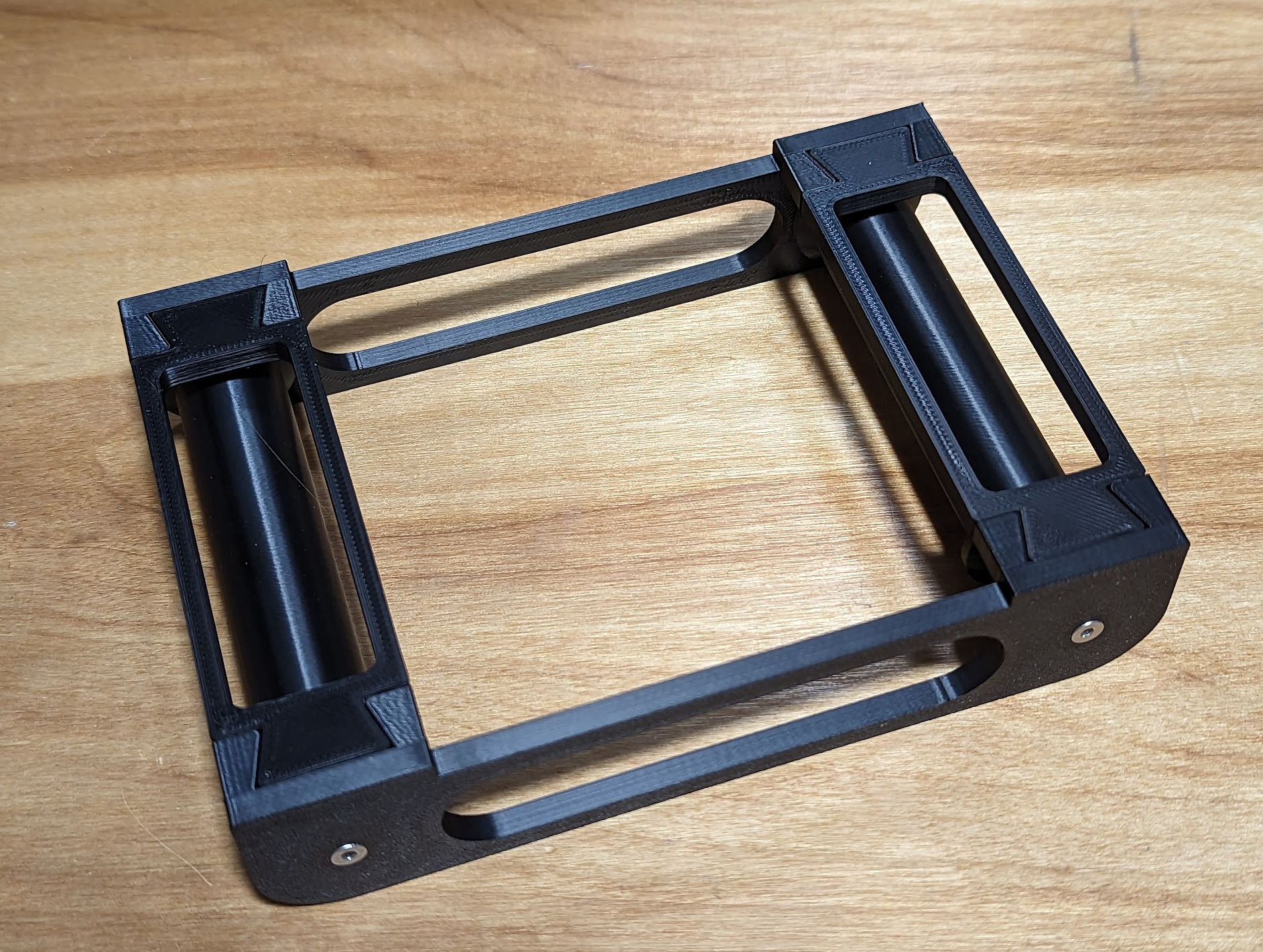
There are many 3d-printable filament roller designs. This one is highly parametric, designed to be easy to modify to fit different constraints. Big reels, small reels, thin reels, fat reels, whatever bearings you happen to have on hand or find a really good price on, with clearances that work on your own printer; it's all possible and meant to be easy.
To modify it, all you need is FreeCAD, available for the low, low price of $0 for Linux, macOS, and Windows. If you aren't yet familiar with FreeCAD, to get started, check out FreeCAD for Makers by Jo Hinchliffe ("@concretedog").
If you have the very common 625 class of bearings and some M3 screws, you might be able to use one or more of the 100x127, 90x127, and 80x90 variants included here. Those names are the length of the roller and the inter-roller distance respectively; see the following table for more understanding of those parameters.
Printing
If you are printing the default model that takes M3 screws, or any other model with screws, and do not intend to chase the threads with a tap, you will want thin layers in order to print working thread forms; I used 0.12mm layers in ABS. Other than that constraint, any layer thickness is fine. Three layers and perimeters and minimal infill should work fine for 1kg spools. If you are loading 5kg spools, you'll have to work that out yourself!
Assembly
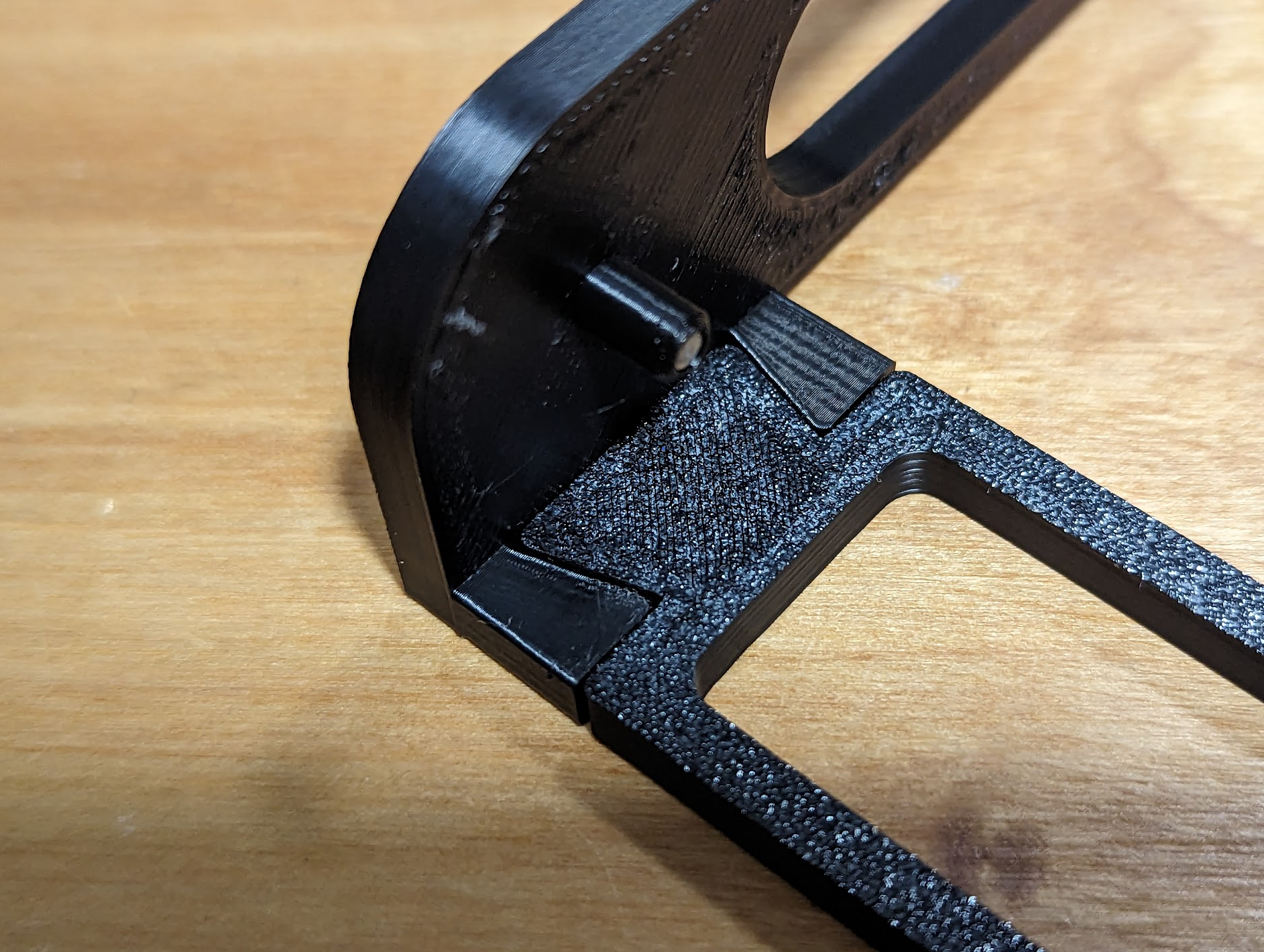
If using screws to make the pegs stronger, screw them into both sides first.
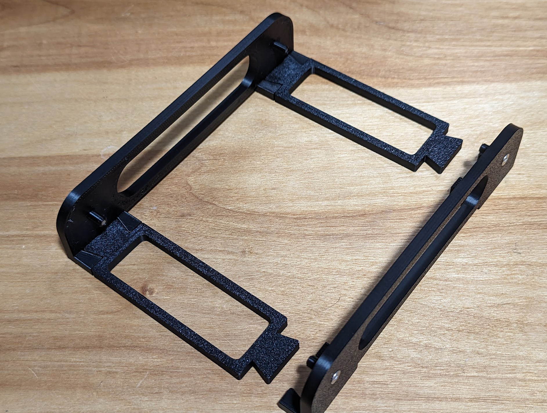
Insert the cross braces into one side. The tabs should hold together from friction.
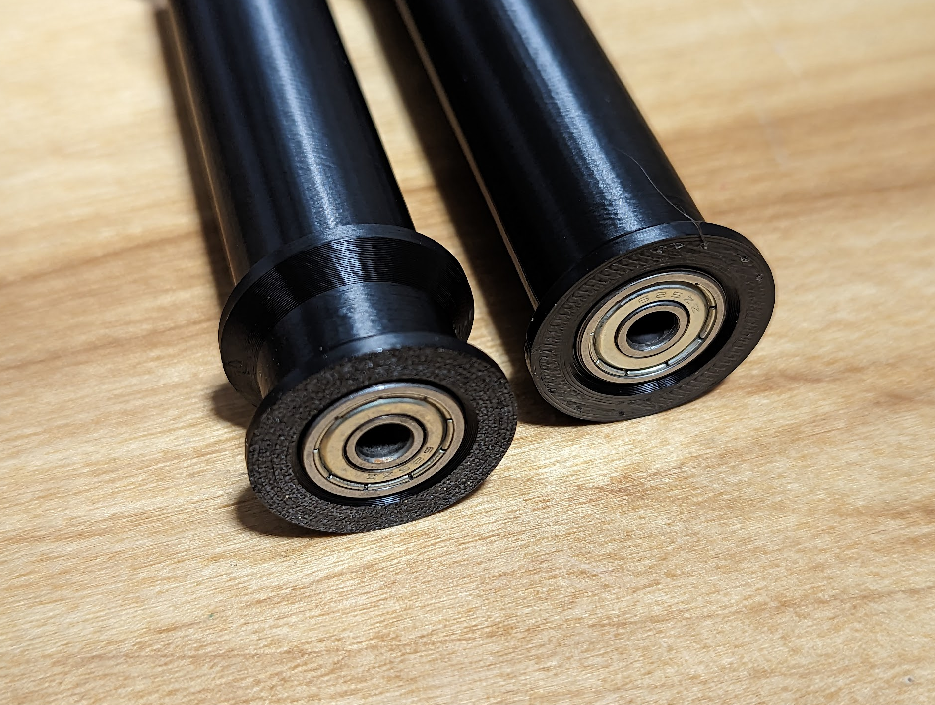
Put the bearings on a flat surface and push the rollers straight down onto them to avoid installing them askew; one bearing in each end of each roller.
Set one side with the pegs facing up and put the rollers onto the pegs, making sure each roller is facing the same way.
Tipping the rollers slightly, put the other side on top with its pegs inserted into the opposite ends of the rollers.
Hold the loose side in place and set it down on the cross braces and insert the tabs into the loose side to lock the assembly together.
Modification
If you use a bearing with a relatively small inside diameter, such as the 5mm inside diameter of the nearly ubiquitous 625 bearing, you probably want to use a screw through the roller supports to add strength. Therefore, the rendered objects included are configured to require those screws.
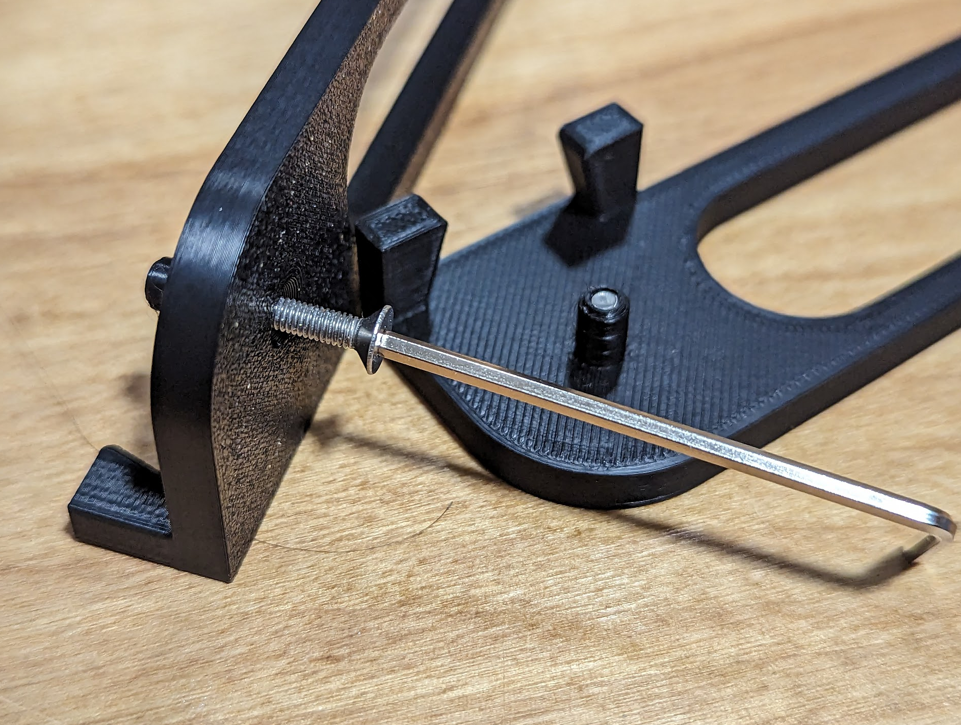
If you use a bearing with a relatively large inside diameter, such as one with 8mm ID, you might not need a screw. If so, go to the SideSupport part, right click the the PegEndChamfer, select "Set tip", and export the part without the hole. If you use a different screw than an M3 countersink screw, instead change the Hole at the end of SideSupport to match the screw. As of this writing, FreeCAD does not have the capability to model extra screw clearance to make up for printer imprecision, so depending on your printer you may need to chase the thread with a tap.
The parameter values marked in green on the spreadsheet p (short for parameters) are intended to be modified by users. The parameters in yellow are calculated and should not be directly modified unless you intend to change characteristics of the fundamental design. (In which case, you do you, but I have made no attempt to make the design robust with respect to changes to calculated parameters.) It is easily possible to create nonsense that will not render. No attempt has been made to detect or prevent these kinds of problems. If, for example you set a larger inside diameter than outside diameter, no attempt is made to catch or warn.
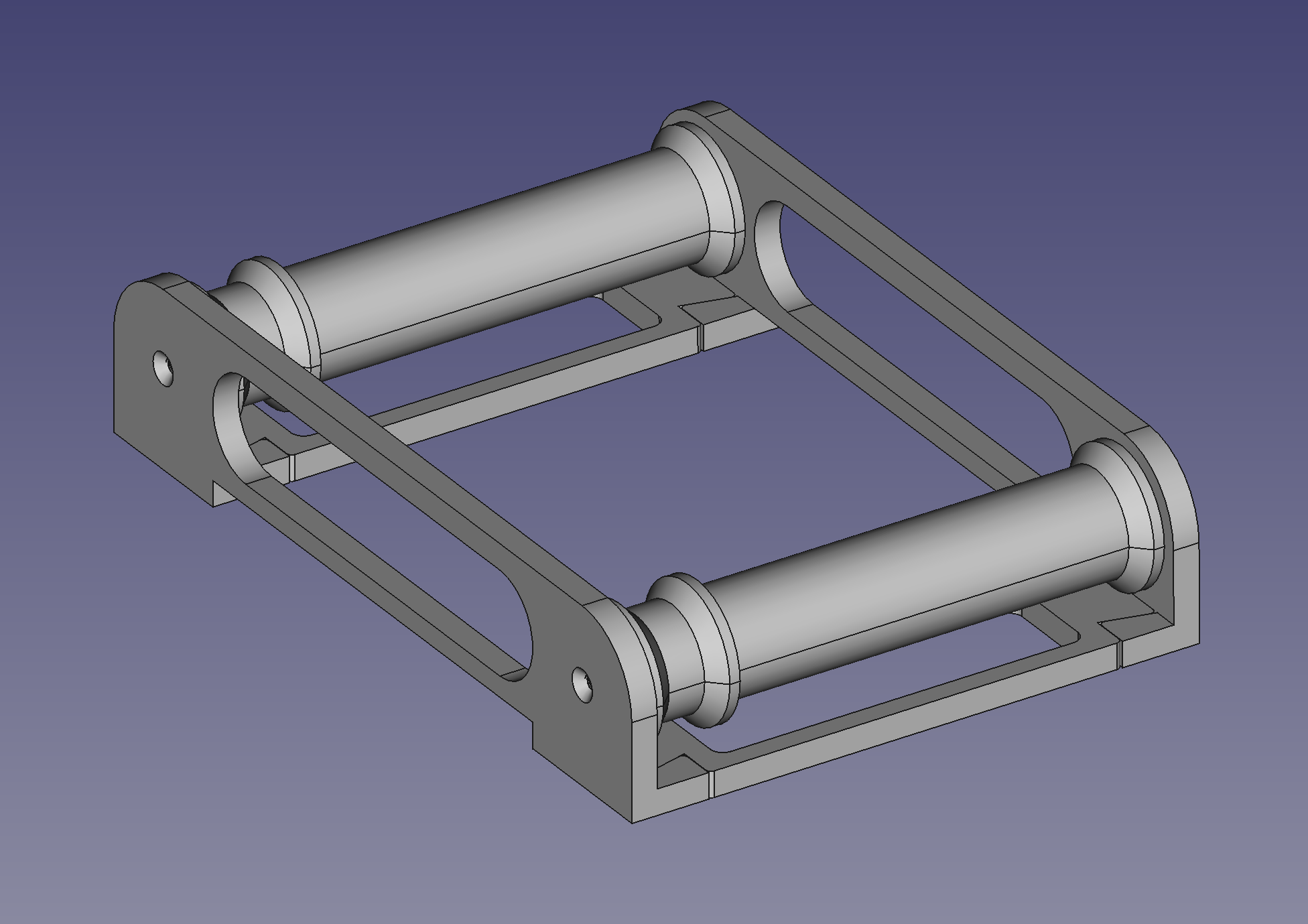
You can see what the assembled version should look like by loading Assembly.FCStd. This requires the Assembly4 work bench, available in FreeCAD's Tools→Addon manager if you have not yet installed it. The Assembly4 work bench is not requires for working in the FilamentRoller.FCStd file that defines the parts.
What are you waiting for? Find four of some kind of bearing, get out your calipers, measure your bearings and filament reels, and make this thing yours.
Parameters
| Parameter |
Default Value |
Notes |
| Bearings |
|
|
bearingInsideDiameter |
5 mm |
default is for 625-class bearing |
bearingOutsideDiameter |
16 mm |
default is for 625-class bearing |
bearingThickness |
5 mm |
Including the flange, if any; default is for 625-class bearing |
bearingFlangeDiameter |
18 mm |
This creates a chamfer for ease of install for non-flanged bearings |
bearingFlangeThickness |
0 mm |
|
bearingClearance |
0.1 mm |
Added to outside radius of bearing; test print one roller just longer than the bearing thickness to adjust on your printer and settings |
bearingIdClearance |
0.15 mm |
Subtracted from the diameter of the roller supports |
|
|
|
| Rollers |
|
|
rollerLength |
100 mm |
The default outer flange sizes support a reel of width 10mm less than the roller length; see Maximum Roller Width calculated parameter |
rollerOutsideDiameter |
20 mm |
The diameter of the section of the roller supporting the edge of the reel |
rollerOutsideFlangeDiameter |
26 mm |
The diameter of the larger section holding the reel in place |
rollerInnerFlangeDiameter |
12 mm |
Must be smaller than bearingOutsideDiameter; holds the bearing in place at the end |
rollerInnerFlangeThickness |
1 mm |
|
rollerFlangeThickness |
2 mm |
|
rollerGuttterThickness |
7 mm |
Width of sections constraining one reel edge |
|
|
|
| Frame |
|
|
frameThickness |
5 mm |
|
interRollerDistance |
127 mm |
Distance between centers of rollers |
footWidth |
30 mm |
The foot contains the negative tab that holds the cross brace tab |
tabLength |
10 mm |
|
tabMajorWidth |
20 mm |
|
tabMinorWidth |
15 mm |
|
tabClearance |
0.1 mm |
If the tabs don't fit, add appropriate clearance for your printer |
tabClearanceRadius |
1 mm |
|
rollerEndClearance |
0.5 mm |
This is the clearance at each end of the roller; total contributes 2x to full width of set |
frameSlotRadius |
10 mm |
|
|
|
|
| Cross Brace |
|
|
slotCornerRadius |
2.5 mm |
|
License
This work is licensed under a Creative Commons Attribution 4.0 International License.
Source
Maintained in Gitlab
:format(webp)/https://fbi.cults3d.com/uploaders/14535803/illustration-file/63827f5d-b06e-4a20-b4a8-69b2659d3f40/Screenshot-from-2023-09-07-21-50-47.png)


/https://preview3d-images.cults3d.com/btbax1kmfh9lw8w7nsx82um8b1kn)
/https://preview3d-images.cults3d.com/caw4zil8bszh1aidkosrs4owj4rt)
/https://preview3d-images.cults3d.com/vthikstumsoi27yd455hhukth6dh)
/https://preview3d-images.cults3d.com/mb4kull1voh02njcwsft41z339pn)
/https://preview3d-images.cults3d.com/dsdj8hcq2yw7ledw67ona3pmpswo)
/https://preview3d-images.cults3d.com/cd55k0hh50x5e8tcmotppuphbb0e)
/https://preview3d-images.cults3d.com/wrs8k695dp6qpt4vc9qo1b5rhppj)
/https://preview3d-images.cults3d.com/2ro0qozecsrzmuu9pxdd5ia8gok1)
/https://preview3d-images.cults3d.com/gbih2umhlxnce9y842bh4hs3ol1l)


