DO NOT LEAVE THE GAUGE ON YOUR PRINTER WHILE PRINTING! YOU WILL DAMAGE YOUR PRINTER.
New November 2021: I have uploaded a new version of this gauge mount. See image #6. Rather than snapping the gauge in the holder, the gauge attaches to the mount with a medium size 3M Command Strip. 3M #17021P-RR. A 9-pack is $2.98 at Walmart. See the 7th image above for proper orientation. This makes it better because there is nothing covering the battery door, which in turn makes it easier to remove the battery when not in use. The 'Off' button only turns off the LCD display. The rest of the circuitry remains powered, causing the battery to deplete prematurely.
If you are looking for this gauge mount that fits a 2020 extrusion x-axis rail for your Creality printer or one of its clones, you will find it here: Bed Leveling Gauge Mount for 2020 Extrusion (https://www.thingiverse.com/thing:5093347).
This gauge mount makes it fast and easy for you to level your X-axis gantry with your entire printer bed, corner-to-corner to within +/- 0.01mm of accuracy or better. Your 1st layer will be the most uniform it's ever been, regardless of whether you have auto-leveling or not.
It is also a great diagnosis tool for bed leveling problems. It allows you to readily see precisely how your bed leveling efforts are affecting your bed. Furthermore, it's much, much faster than printing a calibration grid in order to find low and high spots. In other words, you can see your adjustments "LIVE" as you make them.
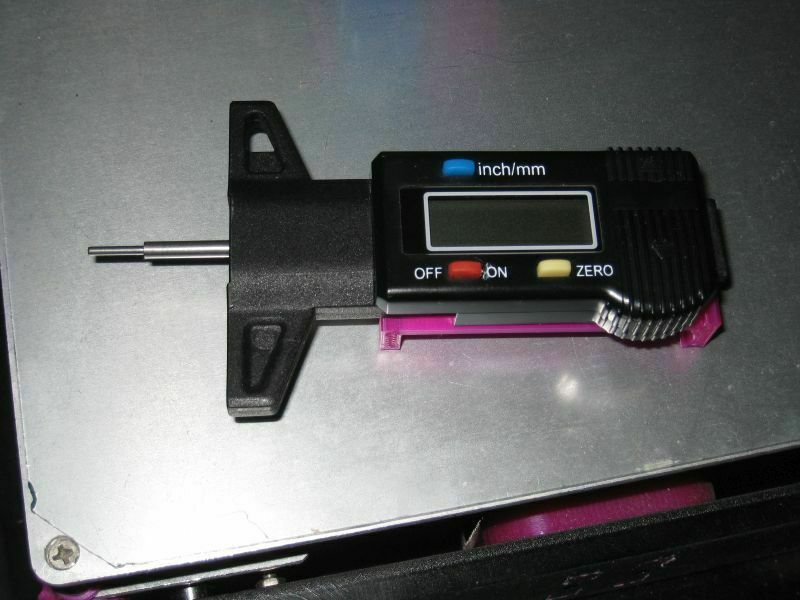
There are a few different versions of these tire tread depth gauges, so make sure you buy the same one. This is the one I bought: Digital Car Wheel Tire Gauge Meter, about $4 Make sure to get one with the metal probe. The other kind may not fit the coupler.
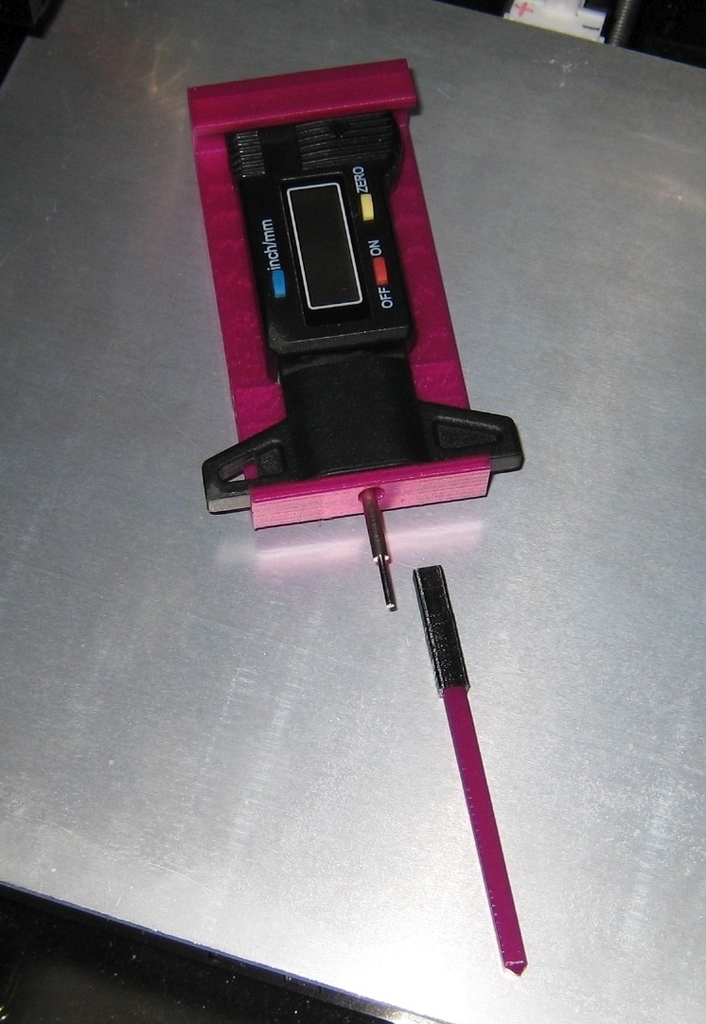
Mounting the gauge:
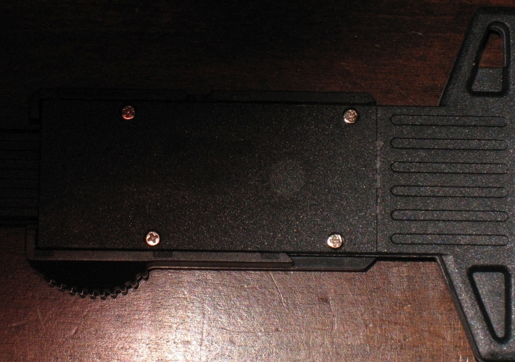
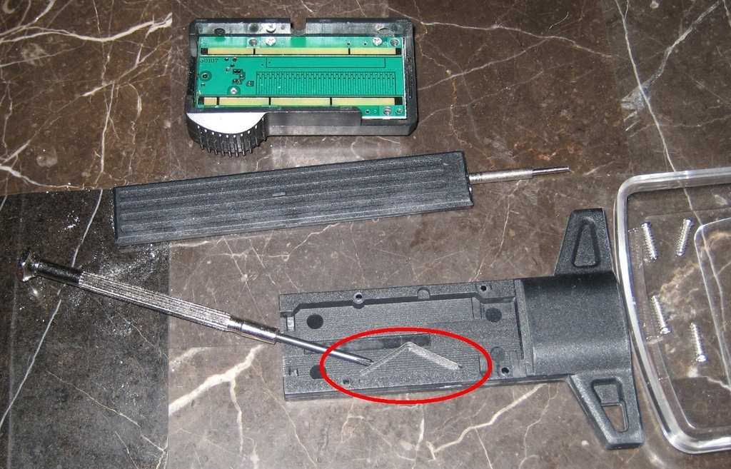
Before putting the gauge in the mount the tension spring needs to be removed. Image #4 shows the back of the gauge with the label removed in order to expose four Philips head screws. Image #5 shows the probe tension spring. Remove this spring and reassemble the gauge. Make sure the probe's blue side is on the same side as the LCD screen.
The benefit of removing the spring is the probe only weighs about 9 grams which minimizes bed deflection and provides ultimate measuring accuracy and repeatability. By comparison, my machinist's dial indicator exerts ~90 grams of force on the bed.
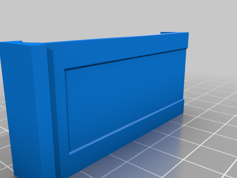
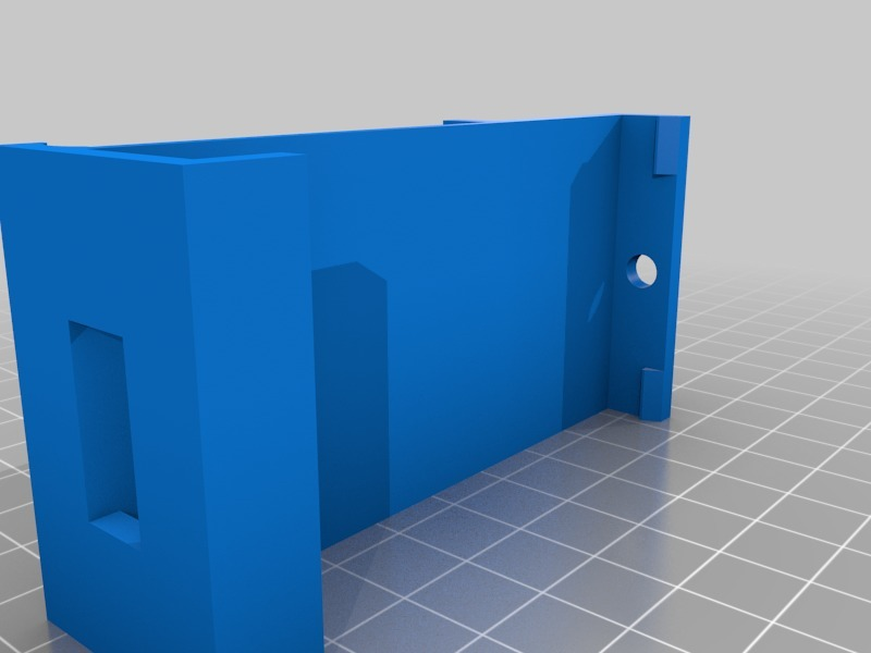
Attach the gauge to the mount by pushing it into place until the mounting tabs give a satisfying snap. No screws or other retainers are required. Check the top and bottom holes to make sure the probe is not binding. The probe needs to drop under its own weight to function properly.
UPDATE 09/06/2018: Auto leveling is helpful. I have it. But an auto bed leveler can only square the X-axis gantry to the bed. It cannot square the bed with the frame. A bed that is not square with the frame prints parallelograms in the Z-axis vertical plane (like the Leaning Tower of Pizza), not rectangles with 90 degree corners.
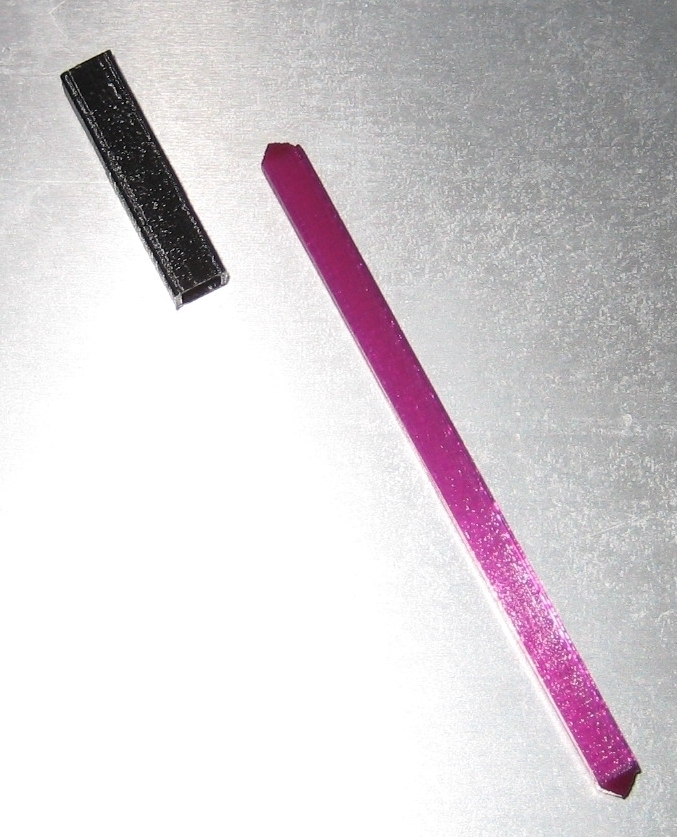
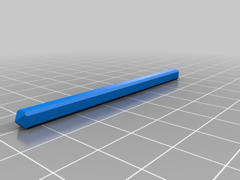
For that reason, I have created a probe extension and coupler that allows you to perfectly square your bed with your frame. This should be done first. Complete instructions to square your bed with your frame are located at https://www.thingiverse.com/thing:3087459.
The coupler and extension STL files are now included when you download this thing. Be sure to see print requirements for the coupler and extension in the link above.
X-axis Belt Alignment (optional):
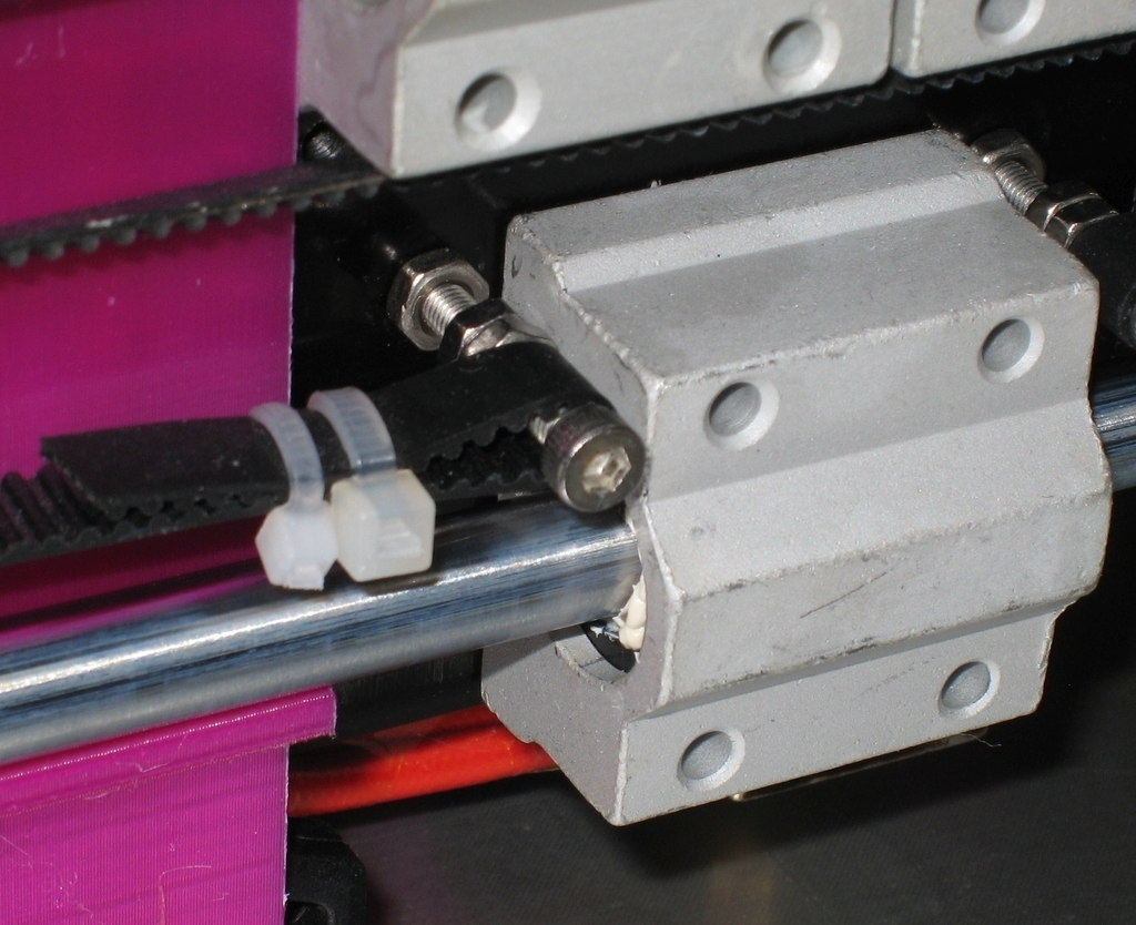
In my case the tire gauge mount would not hang freely when butted up next to the extruder. Anet provides two M3 x 18mm screws to mount the X-axis belt to the extruder assembly. Because they are too short, they cause the belt to be misaligned with X-axis rods. This makes the belt push the gauge mount away from the rods making it impossible for the mount to hang freely when slid against the extruder.
I could still move the extruder to the far left or right side while the extruder was in the middle of the bed to take a measurement and use it that way, but I have a perfectionist streak in me so that would not do. I wanted to be able to measure every square centimeter of the bed.
Before using the gauge I replaced the extruder's M3 x 18mm belt screws with longer 25mm ones so the belt was properly aligned with the pulleys and rods. Now the belt does not touch the gauge mount anywhere along the X-axis gantry. These 25mm screws are what Anet should have provided in the 1st place for proper pulley, rods and belt alignment. See image #2.
Using the gauge the easy way. Updated 08/23/2018:
* Put the extruder in the Home position. Turn printer off and center the extruder in middle of the bed. Leave it there. Image #1.
* Attach the gauge so the probe is reading the left edge of the bed. Zero the gauge.
* Move the gauge to the right side of the bed and take a reading.
* Example for a negative reading: Right side reading is -0.20. Divide -0.20 by 2 = -0.10. Multiply -0.10 by -1 (negative one) = +0.10. (A negative number times a negative number is a positive number.) Adjust the right Z-motor until it reads +0.10.
* Example for a positive reading: Right side reading is +0.20. Divide +0.20 by 2 = +0.10. Multiply +0.10 by -1 (negative one) = -0.10. (A positive number times a negative number is a negative number.) Adjust the right Z-motor until it reads -0.10.
* Now let's check if we are level. Zero the gauge while it is still mounted on the right side.
* Move the gauge back to the left side of the bed and take a reading. You should now be within +/- 0.01mm of level. If not, repeat one more time. If you repeat these steps a second time you can usually achieve 0.00mm to 0.01mm of leveling.
* This gauge is very sensitive. If your arms are resting on your desk it will affect your accuracy.
* From this point on you only need to adjust the right Z-motor to get your X-axis level.
* The gauge has both inches and mm modes. Either mode works well. Chose the mode that is easiest for you.
You will find these steps are much faster and easier to do than they sound.
-VegasGuy
:format(webp)/https://fbi.cults3d.com/uploaders/30142993/illustration-file/c6dd1a08-eaeb-4b1c-91ac-24d4713868bf/IMG_3931A.jpg)


/https://preview3d-images.cults3d.com/7tapp54vtarsjpo7lzzbk5if9fcl)
/https://preview3d-images.cults3d.com/eba1b838cn0un36b925gjrympymo)
/https://preview3d-images.cults3d.com/xxejn0u7l8w6n9t20mx7haklhgtu)
/https://preview3d-images.cults3d.com/mi3mc6ffqapvr39teukz8r50zs7q)


