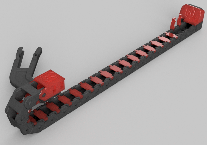
Sidewinder X1 Bed Side Cable Chain Relocation
Preparing to put my Sidewinder inside an enclosure I was not happy with the space taken up at the back of the printer by the bed wiring and needed a solution to fix the kinking from the stock wiring routing. I was inspired by the Bed Cable Side Chain mod by Whoppingpochard posted at prusaprinters.org. (https://www.prusaprinters.org/prints/54320-artillery-sidewinder-x1-genius-illuminated-bed-cab) The mod relocates the bed heater and temperature sensor wires from the back of the printer to the right side, routing the wires through the hole in the chassis next to the Z extrusion frame.
With my printer setup there were some challenges which needed to be overcome.
1. The arm chain connector was too close to the bed causing the fan shroud to collide with it.
2. On my printer the arm was slightly too thick interfering with the bed leveling knobs.
3. Integrate the mounting hardware for the Y carriage arm to streamline the installation process.
4. I wanted to constrain the drag chain so that it could not pivot upward potentially adding a strain point on the wiring.
5. Design my own printable drag chain for use with the mod as the chains from Amazon all had a pronounced bow to them and do not sit flat with the printer housing.
To solve the above items, I recreated the models in Fusion 360 from scratch.
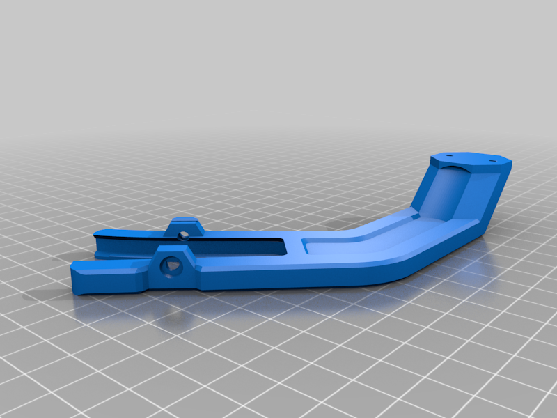
* Extended the Carriage Arm to set the chain mounting connection outside the interference area of the X axis carriage and fan shroud.
* Reduced the bottom thickness of the arm where it slips over the Y carriage arm. It now only extends below the carriage by 1.4mm instead of 2mm and the overall thickness of the main part of the arm has been reduced from 8.8mm to 7mm. This allows complete clearance for the leveling knobs.
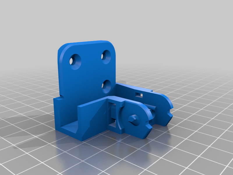
* Integrated an M3 screw and M3 nut into the upper portion of the mounting arm.
* Created my own drag chain with internal dimensions of 10 mm x 15 mm. Pitch of 20 mm which constrains the maximum rotation to 51.4 degrees. The chain is an inside open design with cover clips which can rotate 90 degrees to allow access to the wiring inside.
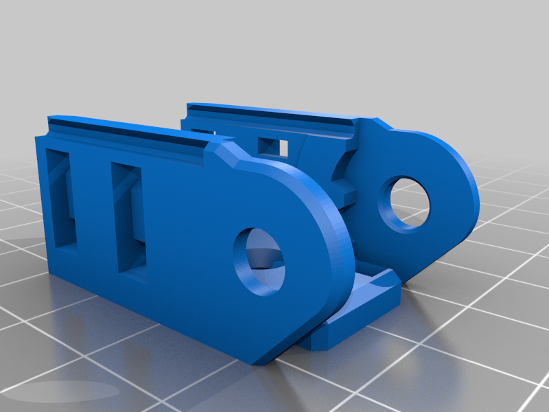
* Raised the arm connector pad so that it lines up with the bend radius of the new drag chain.
* Created a new fixed frame mount for the drag chain with enough space to house the wiring for the bed and the Z axis end stop. Created a cover to hide the wires with exit gap at the top for the end stop wire to extend up the extrusion.
* Additionally, I enlarged the connector cover so that it slides over both sides of the connector locking itself in place. The original would flex enough that it would not stay in place securely and slip out as the bed moved.
PRINTED PARTS REQUIRED
Bed Side Cable Chain File List
Part NameQuantityDescription
Carriage Clamp Arm
1
Mounting arm for the front right side of the Y Carriage.
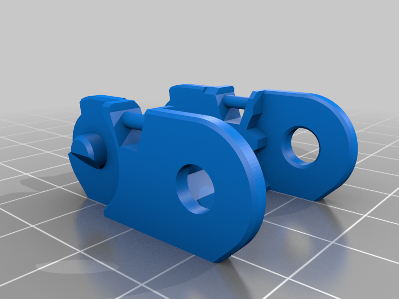
Drag Chain Arm Connector
1
Mount onto the clamp arm pad adding connection point for the drag chain.
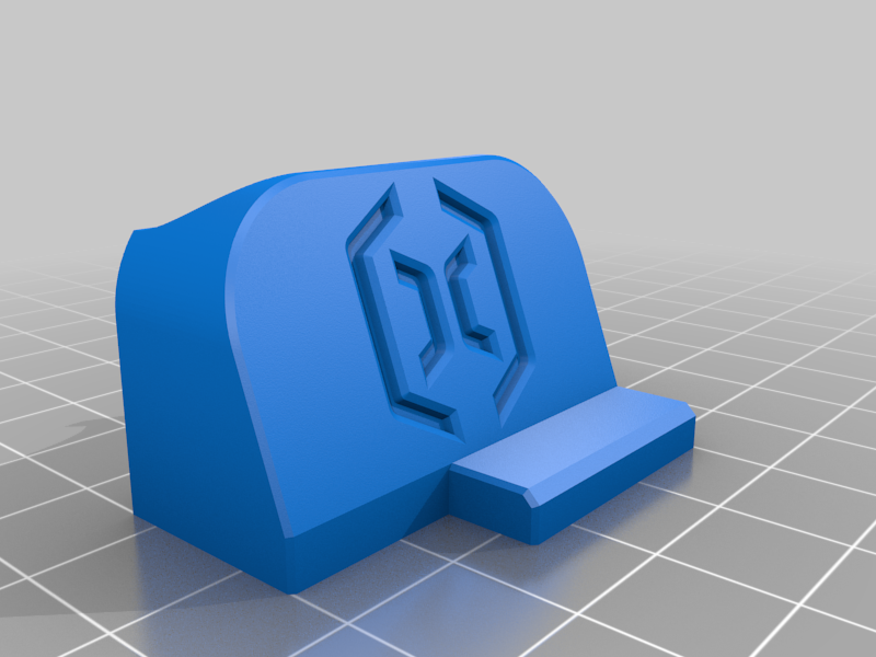
Chain Connector Top Cover – Artillery Logo
1
Cover for connector housing hiding the wiring.
Chain Frame Mount
1
Mounts to the Z frame extrusion on the right side of the printer. Provides a fixed connection to the drag chain keeping it flat against the printer body along the right most side of the printer.
Frame Mount Cover
1
Covers the frame mount hiding the wiring within and the mounting hardware.
Chain Link
21
The links of the cable chain.
Chain Link Cover Clip
21
The top cover for each chain link.
ADDITIONAL HARDWARE REQUIRED
Mounting Hardware
Name
Quantity
Description
M3 x 30 mm Flat Head Screw
1
Clamps the Carriage Clamp Arm
M3 nut
1
Press into slot on clamp arm for M3 x 30 mm screw to thread into.
M3 x 8 mm Flat Head Screw
5
3 (optional 2) as mounting hardware for Chain Frame Mount. 2 for attaching the Drag chain arm connector to the arm.
M3 Hammer T-Nut
3
(Optional 2) Mount the Chain Frame Mount to the aluminum extrusion.
Small zip ties. I used 10 cm x 2.5 mm zip ties.
*
Used to secure the wires at each end of the cable chain and for cable management inside the printer.
WIRING REQUIREMENTS AND OPTIONAL CONSIDERATIONS
The bed heater wires are not long enough for the new route and a plan must be made to either extend them or replace them. At a minimum you will need to splice in about 8 inches for the two power wires to accommodate the new path to the power supply and relay. You can use heat shrink butt connectors for this. The temperature sensor wire is long enough to make the new path without alteration.
I chose to replace the bed heater wiring with a new pig tail using a Molex Micro Fit 3 connector. I wanted to be able to disconnect the bed entirely from the printer easily to make working on the printer easier and make the installation simpler as I would not need to fight the cabling.
I also chose to sleeve the power wires individually as well as the temperature sensor wires.
My implementation for the wiring used the following parts.
Item
Quantity
Description
18 gauge silicone wire
62 inches
I used two 32” lengths of the red wire to create my extension. This was enough to go from the power supply to the bed side connector comfortably.
Molex Micro-Fit 3.0 dual row (4 Circuits) Male & Female receptacle plug, w/Terminal sockets
1 Male
1 Female
4 male crimp pins
4 female crimp pins
Pigtail connector used at the bed side connection. Make sure you have extras as crimps could go wrong.
Heat Shrink Connectors Ring Terminals 22-16 AWG 1/4"
2
While I linked to the crimper and terminal set I only used two of the red 22-16 AWG ¼” ring terminals for the power supply and relay ends of the bed heater wire extension.
MDPC-X Sleeving Red Carbon
6'
I used some leftover sleeving from computer projects to sleeve my wires. I used the Red Carbon for the power wires, as it seemed appropriate.
MDPC-X Sleeving Liquid Carbon
3'
Sleeving for the temperature sensor wires.
I cut the factory loom from the bed wires and then cut the heater and temperature sensors wires about 2 and a half to 3 inches from the bed. I adjusted the cut length to give a curve when the Molex connector was assembled into where the cable chain connector would be located. I reused the stock wire cut off from the temperature sensor in the Molex connector so I would not need to crimp another JST plug at the other end where it goes to the main board. If I were to do it again, I might choose to do two plugs, one for the bed and a second for the temperature sensor instead of doing them all in one plug.
INSTALLATION INSTRUCTIONS
Print the following files.
Carriage Clamp Arm
Drag Chain Arm Connector
Chain Connector Top Cover - Artillery Logo
Chain Frame Mount (Optionally there is also model with an integrated cable guide for 3 wires with 4mm diameter. This is the one I used with my sleeved cables.)
Frame Mount Cover
21 Chain Link
21 Chain Link Cover Clip
Remove the Bed
Make sure the printer is off and unplugged from the wall!
Disconnect the heated bed wires from inside the printer at the power supply and relay.
Disconnect the bed temperature sensor wire from the lower right side of the main board.
Feed the wires through the hole in the back of the printer.
Remove the leveling knobs under the bed.
Lift the bed off the Y carriage. Set aside the springs for use later.
Install the Carriage Clamp Arm
Insert an M3 nut into the slot at the top of the rear clamp wing. Press firmly with screwdriver to ensure it is fully seated.
Slide the Carriage Clamp Arm onto the front right arm of the Y carriage.
Insert the M3 x 30 mm screw through the hole on the front clamp wing into the nut at the rear and tighten.
Assemble the drag chain
Push the links together using the angled side of the side pins to expand the wings with the holes until they click together.
Attach the Chain Frame Mount to one end of the drag chain.
Attach the Drag Chain Arm Connector to the other end of the drag chain. This should be oriented so that the top opening of the connector is facing the outside of the chain (opposite of the open side of the chain links themselves.)
Secure the Chain Frame Mount using M3 x 8mm screws with T nuts to the vertical Z axis extrusion on the right side of the printer.
Wiring
Route the wires through the hole on the right side of the frame next to the Z axis extrusion mount right next to where the Chain Frame Mount is attached.
Run the wiring along the inside of the cable chain through the Arm Connector.
Install the bed onto the Y carriage turning it 90 degrees to the right from stock. This should place the wiring near the Carriage Clamp Arm on the right side of the printer. Reinstall with the leveling springs and then screw on the leveling knobs.
Bend the cable chain up at the front of the printer 180 degrees so that the bottom of the Arm Connector sits on the top pad of the Clamp Arm. Secure with two M3 x 8mm screws.
Secure the wires using zip ties at the connector side near the bed. This is so they are held in place for when you reconnect the wiring inside the printer.
Reconnect the bed heater wires to the power supply and relay. Then reconnect the temperature sensor to the main board.
Feed any extra cable down inside the printer. Leave some slack in the wires through the drag chain and then secure the wiring at the Chain Frame Mount end of the drag chain. The cables should have enough slack in them to allow some movement while the printer is in operation. You don’t want them pulled too tight.
Install the Chain Link Cover Clips onto the drag chain links to close the chain.
Slide the Cover pieces into place over the Chain Frame Mount and the Drag Chain Arm Connector.
Edit 2021/08/07: Added Genius Carriage Clamp Arm
I have modeled a clamp arm for the Genius and added it to the file list here. This clamp arm also uses an M3 x 30mm screw, so no difference there. The drag chain will likely only need 17 chain links instead of the 21 links for the Sidewinder. Everything else should be the same between the two printers.
Edit 2021/08/19: Added Fusion F3D File and Step file
:format(webp)/https://fbi.cults3d.com/uploaders/27946472/illustration-file/49a45606-aac7-40ab-9e63-463e5067ffb0/Bed_Side_Cable_Chain_-_Black_and_Red.png)


/https://preview3d-images.cults3d.com/x7s0b5saw66flj5076hk0phiw9ak)
/https://preview3d-images.cults3d.com/6m123bi9g0z9ccp6g1ak0cmi9z24)
/https://preview3d-images.cults3d.com/m0l2gftf5ds1astxos0ercpfvfs1)
/https://preview3d-images.cults3d.com/95q3nv3r6y3vsv9epfv4iqdrk7kj)
/https://preview3d-images.cults3d.com/7rahx0ux0jqjprnx9qsylyweqogc)
/https://preview3d-images.cults3d.com/eq5hvftro020jx4mjdls9czvrlf3)
/https://preview3d-images.cults3d.com/sdgtscq4zlcn36tbilkp9ckkeqfp)
/https://preview3d-images.cults3d.com/j8prz3zzno4d07t87x5tjmvdopzk)
/https://preview3d-images.cults3d.com/4wmj4aum6qz1d7myuurs8ys6zwms)


