Skip to content

3Drag / K8200 - Optical end stop for X, Y and Z axis

Advertising
Advertising
?
Creation quality: 0.0/5 (0 votes)
Evaluation of members on the printability, utility, level of detail, etc.

  • 269 views
  • 4 downloads

License
3D design format
Folder details Close
  • end_stop_X_Y_axis_1of2.stl
  • end_stop_X_Y_axis_2of2.stl
  • end_stop_Z_axis.stl

Learn more about the formats

Publication date 2023-04-25 at 23:39
?
Published to Thingiverse on: 2016-08-21 at 03:43
Design number 1187903

3D printer file info

3D model description

The end stops for the X, Y and Z axis in the 3Drag / Velleman K8200 printer are simple switches that may introduce noise to the controller board that may result in an unwanted shift between the plastic layers printed.

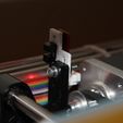
Here I present a simple set of components that can be used to replace the all switches by optical end stops. The pieces are designed to be used with the Optical Endstop Light Control Limit Optical Switch for 3D Printers RAMPS 1.4 that can be bought in aliexpress.

X axis

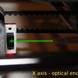
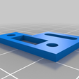
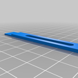
Print the files end_stop_X_Y_axis_1of2.stl and end_stop_X_Y_axis_2of2.stl. The first component is used to mount the optical end stop circuit to the X-axis stepper motor. The second element is mounted on the moving platform in the position where was located the screw that activates the switch. This component is used to block the light in the sensor (see picture).

Y axis

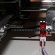
Print (again) the files end_stop_X_Y_axis_1of2.stl and end_stop_X_Y_axis_2of2.stl. The first component is used to mount the optical end stop circuit to the plastic component where the switch for the Y-axis is located (see picture). The second component is mounted also on the moving platform in the position where was located the screw used to activate the switch.

Z axis

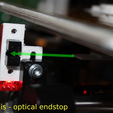
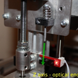
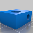
In this case, the sensor is attached directly to the Z-axis stepper motor. The plastic component end_stop_Z_axis.stl is used to set the position of a screw that blocks the light on the sensor (see picture).

** Important **
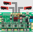
Don't forget that in order to be able to use optical end stops, a bridge between 5v and GND has to be soldered, as shown in the circuit figure. Please pay attention to the correspondence between the board pins and the optical end stop pins (in the figure are shown only for illustrative purposes).

Advertising


Issue with this design? Report a problem.

Would you like to support Cults?

You like Cults and you want to help us continue the adventure independently? Please note that we are a small team of 3 people, therefore it is very simple to support us to maintain the activity and create future developments. Here are 4 solutions accessible to all:

  • ADVERTISING: Disable your banner blocker (AdBlock, …) and click on our banner ads.

  • AFFILIATION: Make your purchases online by clicking on our affiliate links here Amazon.

  • DONATE: If you want, you can make a donation via Ko-Fi πŸ’œ.

  • WORD OF MOUTH: Invite your friends to come, discover the platform and the magnificent 3D files shared by the community!


Sharing and downloading on Cults3D guarantees that designs remain in makers community hands! And not in the hands of the 3D printing or software giants who own the competing platforms and exploit the designs for their own commercial interests.

Cults3D is an independent, self-financed site that is not accountable to any investor or brand. Almost all of the site's revenues are paid back to the platform's makers. The content published on the site serves only the interests of its authors and not those of 3D printer brands who also wish to control the 3D modeling market.

100% secure payment by credit card, PayPal, Apple Pay, Google Pay, etc.
View all payment options.