Background
I was using an inductive sensor as my main Z_min sensor. I was unable to use it as bed leveling sensor because I was using a very thin and soft steel plate under the glass. This lead to several issues: the glass itself is not perfect. The steel plate under it was not flat even when compressed so both the steel and glass does not represent the REAL printing surface. Only a touching probe can give you that!!!
I like the idea of the piezo - but also plan to use PEI in the future and I would not like to touch a hot nozzle to that surface.
I like a lot the BLTouch - but the real thing is too expensive to my tastes and the clones are not that reliable and not so cheap as well.
I do not like the bulky thing, with movable wires and such, when using a servo and a mechanical end-stop. Also I do not trust the repeatability of the servo positioning.
I fall in love with these two designs:
Robscar Thing (https://www.thingiverse.com/thing:2841443)
Jupacreations Thing (https://www.thingiverse.com/thing:2197895)
Cheap as heck, simple, reliable, no dependency on servo position (the servo just raise the probe when not in use). But both are bulky and very specific to their owners printers.
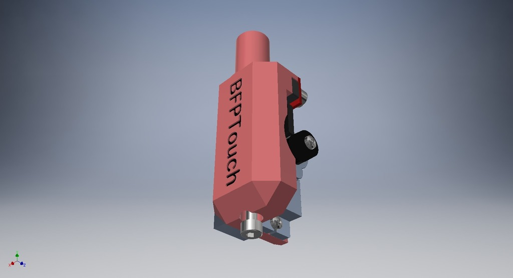
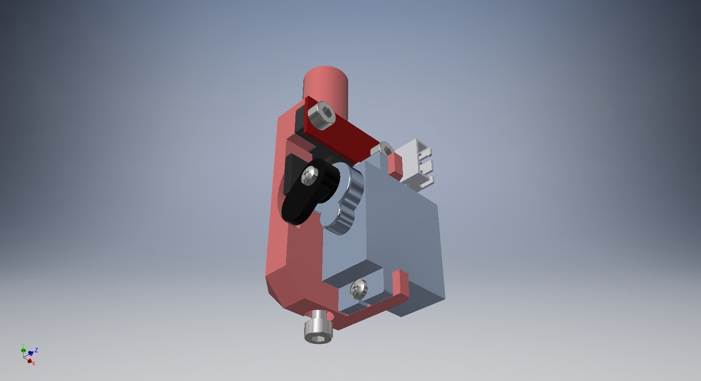
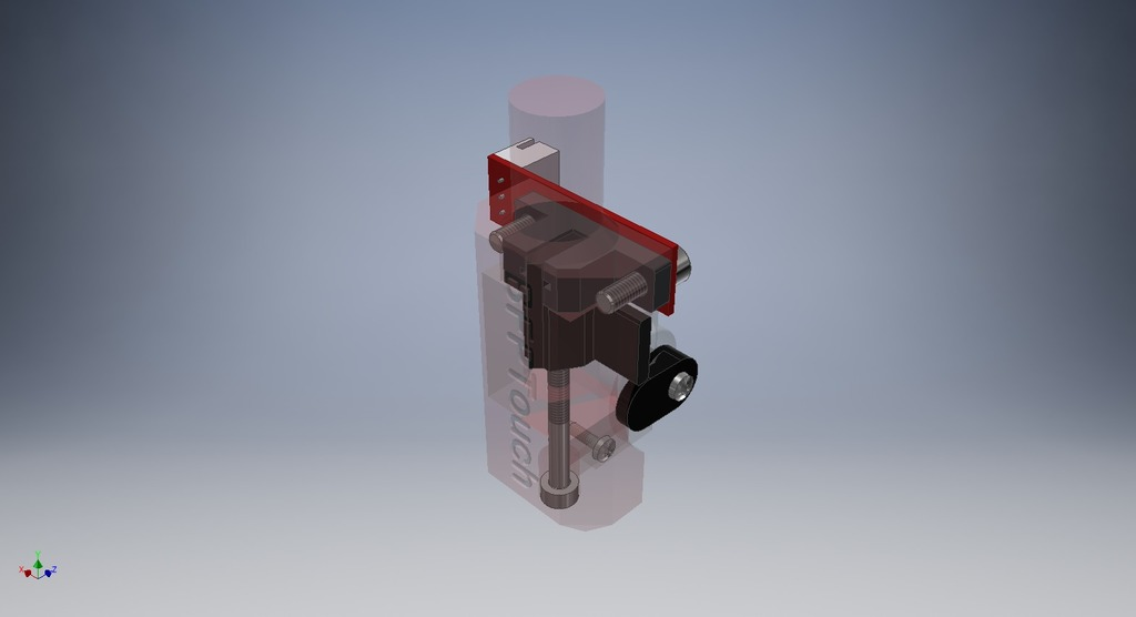
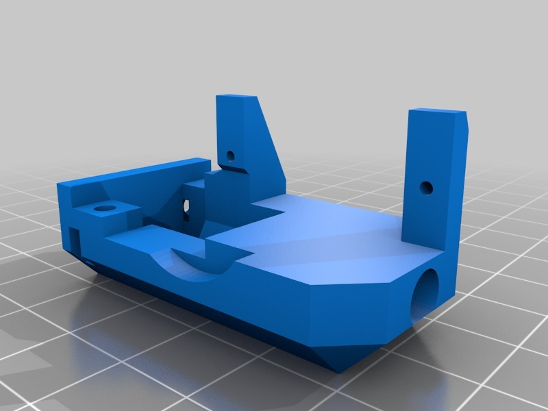
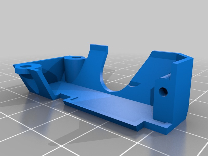
So I started designing something I could just put in place of my old inductive sensor at my Hypercube Evolution. That is compact enough for any other printer (different fixation designs on demand! Just ask me.). The size is based o the BLTouch footprint.
Key Features
Some key features (this list is based on Jupacreations design description!):
- It can be used on all bed surfaces.
- It is not sensitive to temperature changes. **
- What you see is what you get during the working and setup.
- High accuracy and repeatability (better then anything at least at this price range! ;-) )
- Lowest price possible with ready to buy products. (I had everything at hand...)
** Well... it is sensitive to temperature... But my fault: I put the thing right at the heat flow path of the hot end cooling fan! Do not do that!!!! I am working on a solution :D
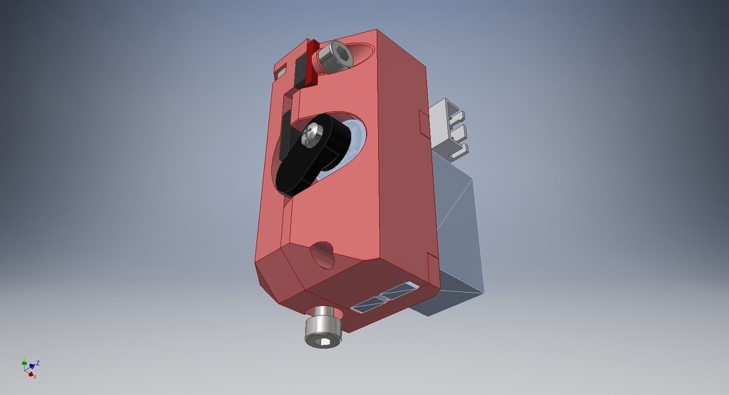
Bill of Materials
You will only need:
* 1x Micro Servo (e.g. TowerPro SG90)
* 1x Optical Endstop TCST2103 (RepRap Standard)
* 2x M3x10 to fix the optical endstop.
* 1x M3x30 as the probe
* 2x self cutting screws (2x8) fix the servo
* 1x Cheap made in China gift pen spring that fits the M3x30 screw.
* Some 4 wire cable **
** I like to use old USB cables for this! It is very common to have the micro USB damaged from use ao the cable is good, felxible, shileded and have nice and stadard colors. Use black and red for feed and the other two for each signal :D.
Instructions
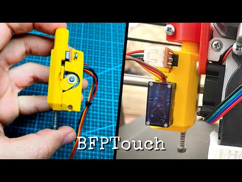
This is a great instructions video complete with Marlin configuration: https://youtu.be/bhuslm04Cus
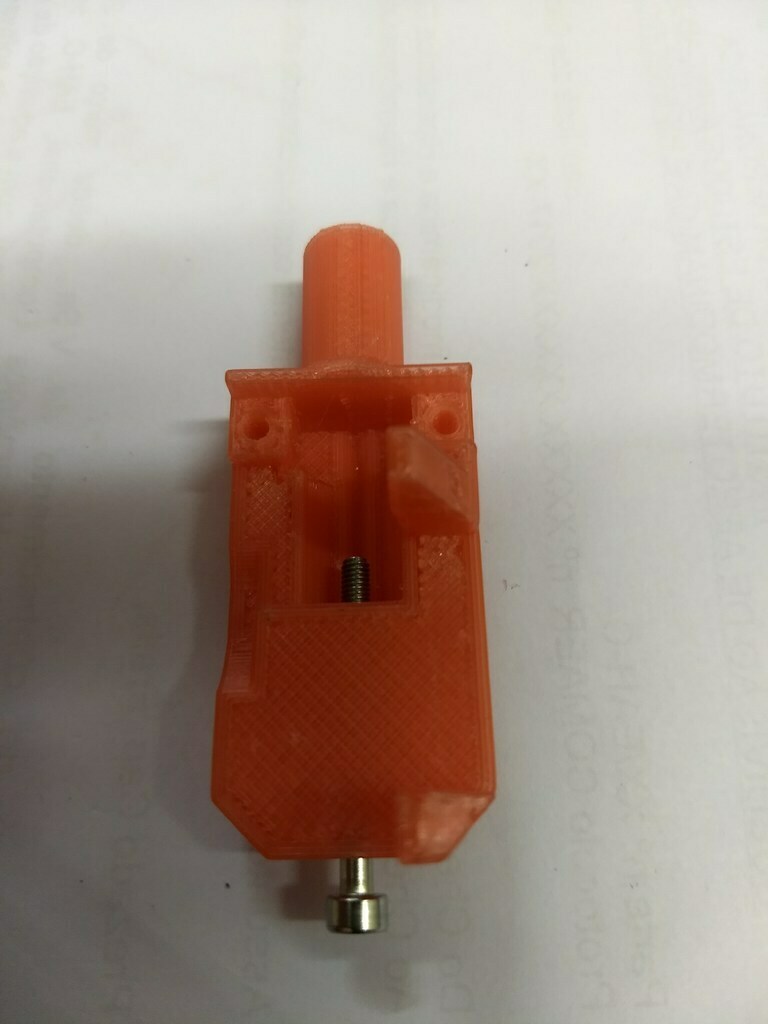
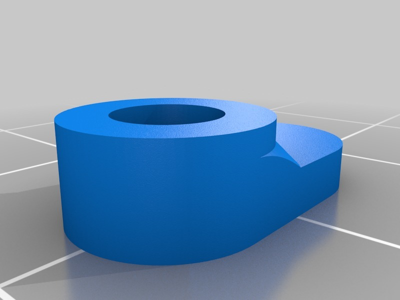
- Print Main and Flag (flag MUST be black or painted black!) parts and test if the flag move freely.
- Put the spring (cut something like 10mm long) at the M3x30 and screw it to the flag mounted to the Main until the head is flush with the flag all way up.
- It need to be as soft as possible! Mount or your printer and manually press 2.5mm the probe to check if it nos moving the sensor body or the gantry in any way. If you note some movement reduce the spring and stretches it;
- Screw the optical endstop and servos.
- Cut to length your servo horn or print one of the options available here (mine fits better with the 4.5mm inner diameter version).
- Do not attach it yet! You need to configure you servo travel carefully before attach it!
- I did use #define Z_SERVO_ANGLES {200,127} but you MUST test it with your servo. 200 is the maximum travel, when deployed, and 173 is retracted.
- Configure your firmware.
- If you use Marlin I do recommend to follow Robscar Thing (https://www.thingiverse.com/thing:2841443) instructions as they are great!
IMPORTANT: IF YOU USE RAMPS YOU WILL NEED AN EXTERNAL 5V SOURCE AS THE ARDUINO CAN NOT HANDLE THE SERVO CURRENT. I am using the same UBEC that I use to feed the Raspberry Pi. Everything is ground common!
Instructions for Duet Ethernet or Wifi
- Connect to the GRD, +5v (pins 1 and 2 of the expansion connector) so supply power to the servo and optical endstop. BE CAREFUL AS YOUR SENSOR OUTPUT IS NOW 5V AND CAN NOT BE CONNECTED TO THE Z_STOP. Connect the servo signal to the pin 31 of the expansion connector (HEATER7) and connect your optical sensor signal wire to the Z_PROBE_IN pin.
- At config.g:
; Z-Probe
M307 H7 A-1 C-1 D-1 ; Disable Heater 7
M574 Z1 S2 ; Set endstops controlled by probe
M558 P5 H5 F120 T8000 ; Set Z probe type to switch and the dive height + speeds
G31 P600 X30 Y0 Z0.217 ; Set Z probe trigger value, offset and trigger height
M557 X47:285 Y5:280 S20 ; Define mesh grid
The offset will be tuned later. Tje Mesh grid is used by G29 and you need to modify to your bed size and type.
Define the points for G32 (you will use this at your start gcode) in your bed.g file.
Configure your deployprobe.g and rectractprobe.g as follows:
; deployprobe.g
M280 P7 S200 I1 ; Deploy probe CHECK YOUR ANGLE VALUE
G4 P300 ; Wait 0.3 sec. (this will give enough time for the servo to extend)
; retractprobe.g
M280 P7 S127 I1 ; Retract probe CHECK YOUR ANGLE VALUE
Do not forgot to configure your HomeX and HomeY to lower the bed before move and HomeZ and HomeAll to send the head to the center of the bed and deploy the probe before homing Z. Also the home Z NEED TO USE G30 INSTEAD OF G1 (hard learned lesson :D) Here are my Home*.g files for reference:
; homex.g
; called to home the X axis
G91 ; relative positioning
G1 Z5 F4000 S2 ; lift Z relative to current position
G1 S1 X-305 F3600 ; move quickly to X axis endstop and stop there (first pass)
G1 X5 F3600 ; go back a few mm G1 S1 X-305 F1800 ; move slowly to X axis endstop once more (second pass)
G1 Z-5 F4000 S2 ; lower Z again
; homey.g
; called to home the Y axis
G91 ; relative positioning
G1 Z5 F4000 S2 ; lift Z relative to current position
G1 S1 Y-285 F3600 ; move quickly to Y axis endstop and stop there (first pass)
G1 Y5 F4000 ; go back a few mm
G1 S1 Y-285 F180 ; move slowly to Y axis endstop once more (second pass)
G1 Z-5 F4000 S2 ; lower Z again
G90 ; absolute positioning
; homez.g
G91 ; relative positioning
G1 Z5 F4000 S2 ; lift Z relative to current position
G90 ; absolute positioning
G0 S0 X119 Y140 F4000 ; move to center of bed
G30 ; move Z down until the switch triggers (first pass)
G1 Z5 F1800 ; go back a few mm
G30 ; move Z down until the switch triggers (second pass)
G1 Z10 F1800 S2 ; lift Z relative to current position
G90 ; absolute positioning
; homeall.g
; called to home all axes
G91 ; relative positioning
G1 Z5 F6000 S2 ; lift Z relative to current position
;==============Home X====================
G1 S1 X-305 F4000 ; move quickly to X axis endstop and stop there (first pass)
G1 X5 F6000 ; go back a few mm
G1 S1 X-305 F180 ; move slowly to X axis endstop once more (second pass)
;==============Home Y====================
G1 S1 Y-285 F4000 ; move quickly to Y axis endstop and stop there (first pass)
G1 Y5 F6000 ; go back a few mm
G1 S1 Y-285 F180 ; move slowly to Y axis endstop once more (second pass)
;==============Home Z====================
G90 ; absolute positioning
G0 X119 Y140 F4000 ; move to center of bed
G91 ; relative positioning
G30 ; move Z down until the switch triggers (first pass)
G1 Z5 F1800 ; go back a few mm
G30 ; move Z down until the switch triggers (second pass)
G1 Z10 F1800 S2 ; lift Z relative to current position
G90 ; absolute positioning
Then follow this instructions for testing and calibrating your offset: Test and calibrate a Z probe
After that send a G29 command to measure and save your mesh and use G32 at your start gcode so it home all axis, measure the tilt and compensate with the mesh grid.
MAKE SURE YOUR MOTORS, BED AND FRAME ARE ALL GROUNDED! I was having issues with static building due to filament and/or belts. This causes the servo to twitch and lose positioning. And also could damage your board :D
And that is it!
Instructions for Klipper firmware by kingfisher (https://www.thingiverse.com/kingfisher/about)
ps.: There is a real need to familiarize oneself with the probe support documents before these instructions make sense!
Here is some sample code to add to the config:
[servo BFPTouch]
set pin to the pin that the BFPTouch servo is connected to.
pin: ar4
initial_angle: 0
enable: True
maximum_servo_angle = 90
minimum_pulse_width = 0.001
maximum_pulse_width = 0.002
Define a probe using the BFPTouch
[probe]
pin: ^ar18
speed: 5.0
z_offset: 1.0
activate_gcode:
SET_SERVO SERVO=BFPTouch ENABLE=1
SET_SERVO SERVO=BFPTouch ANGLE=45
G4 P300
deactivate_gcode:
SET_SERVO SERVO=BFPTouch ANGLE=5
SET_SERVO SERVO=BFPTouch ENABLE=0
Instructions for a skr v1.4 on my Ender3 using Klipper firmware by Kofferkulli (https://www.thingiverse.com/kofferkulli/designs) (08/08/2021)
[servo BFPTouch]
pin: P2.0
initial_angle: 131
maximum_servo_angle = 180
minimum_pulse_width = 0.0005
maximum_pulse_width = 0.0024
[probe]
pin: P1.27 #using
z-endstop pin
x_offset: -42
y_offset: -16
z_offset: 0.77
speed: 3.0
samples: 2
activate_gcode:
SET_SERVO SERVO=BFPTouch ANGLE=180
G4 P300
deactivate_gcode:
SET_SERVO SERVO=BFPTouch ANGLE=131
One has to determine their own servo angles and probe offsets, but maybe this helps someone when setting up Klipper with a BFPTouch.
Development History
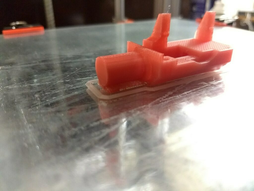
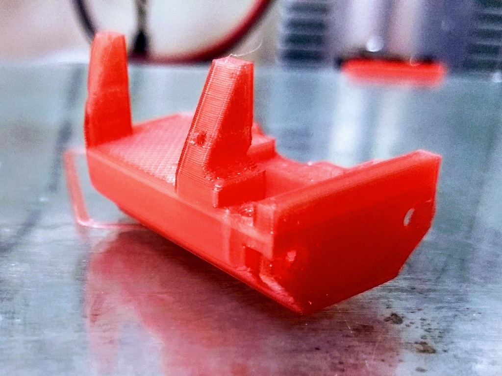
Some photos are from older iterations of the design. Firstly I was counting on gravity alone to release the probe. Then I tried some printed spring design (that failed...) and the M3x30 was fixed to the flag with the head inserted to it. You can see on Mk1 that I cul a channel to be able to put the screw in......:D Then I decided to invert the M3x30 and screw it directly to the flag. And the final mod was adding more space for the spring as a release mechanism. During these iterations I also modified some tolerances.
:format(webp)/https://fbi.cults3d.com/uploaders/13476829/illustration-file/dd378502-a20e-46ef-b318-bfb0d1f5553f/IMG_20180427_161419161.jpg)


/https://preview3d-images.cults3d.com/ir22mwr3nqlw2b7lwj6dn6upq4ci)
/https://preview3d-images.cults3d.com/lly3sul3vwnq5fm51zf1xhsgzcdo)
/https://preview3d-images.cults3d.com/jw4poxf260aib0s0johkl35kpent)
/https://preview3d-images.cults3d.com/14cwmuo2lagyeud4wqczlolpezm9)
/https://preview3d-images.cults3d.com/jxj142xb1d2yu6po1xztkqqee4cv)
/https://preview3d-images.cults3d.com/eturmrxsp1hntfftq33pgkdrdxuh)
/https://preview3d-images.cults3d.com/aro9loqvh6kigqpq4yg28m3okrm8)
/https://preview3d-images.cults3d.com/jiq1tssl4in6bfg34g2rvj2xkbpp)
/https://preview3d-images.cults3d.com/2fac5yma7lnlkoqzen8jgmcro8kg)
/https://preview3d-images.cults3d.com/lfq6gpu748ai23plxgtbwwrfbd6r)


