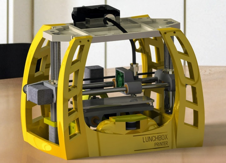
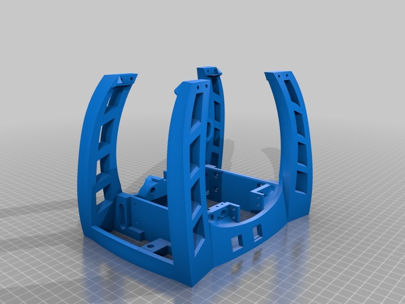
This is a compact and highly portable FDM printer designed to print small, high-resolution components. The entire frame (in yellow) can be 3D printed on a standard size printbed (220mm+). It is intended to be used in situations where a small size and high accuracy is needed. Because of the small size, the hotend is limited to around 220°C safe printing temperature. There is also no heated bed (yet), so PLA is the best bet for now.
The build process isn't too difficult, as long as you have a basic know-how of 3D printers you should be fine.
The frame size is 200x141x153mm. The build volume is 100 x 40 x 50mm. It is intended to be used with a 0.2mm nozzle.
It uses tiny NEMA 8 stepper motors to drive all 3 axes with ease because of the low-mass/inertia of the moving components. In fact, the Bowden tube's bend creates more resistance to the motors than the hotend carriage.
The complete BOM with pricing matrix is included. The current total build cost is $135 USD not including the filament, shipping, or tax. This is if you don't have any parts at all; if you already have the fasteners, zip ties, crimp connectors, PSU etc., it will cut the cost down quite a bit. The most expensive part is the motors, if you can find them cheaper even better.
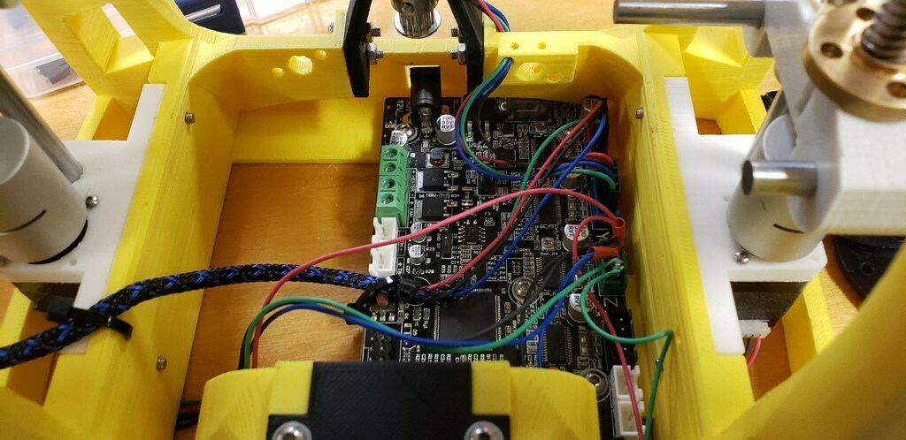
It uses a UM2 style hotend, 6mm linear rods, MKS Mini V1.2 board, and a 12V powerbrick. The bed is just a piece of glass cut to ~100x40mm with four holes drilled in each corner with a Dremel. I'm currently designing a bed mount with higher mounting nuts so that you can fit another 7mm or so in bed size (100x47mm).
#General:
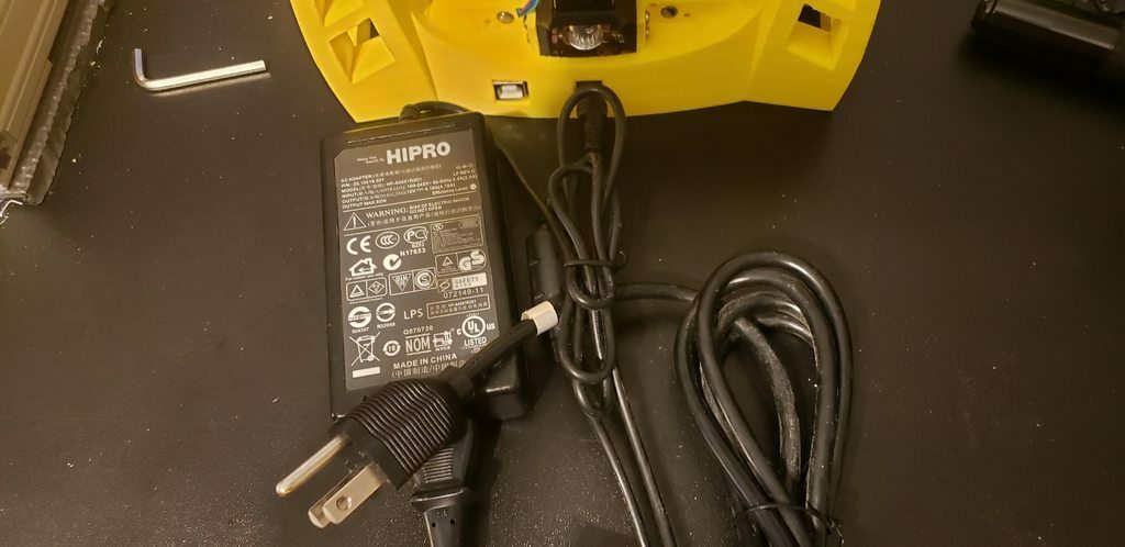
PSU: The MKS Mini 1.2 only supports 12V. I found a small 55W powerbrick that works fine (shown in one of the pictures). Anything more than that is unnessisary (the monoprice mini only has a 70W PSU and it has a heated bed, ~0.6A motors, etc...). The MKS has a standard cylindrical 6mm port.
Motors: Make sure the nema 8 steppers you buy have a holding torque of 2.5oz-in or greater. They are usually 28mm or 30mm. Both will fit. You can go even longer on the X and Y motors if you'd like. The extruder motor I'm using is just a standard 1.8° 25mm pancake. You can use a 0.9° if you wish.
Don't run the motors until you have set the driver currents. The nema 8 motors run at 0.2A max. You will burn them out if you don't. The DRV8825 driver current is just 2 times the voltage, so shoot for 0.1V on your multimeter.
Firmware: This guide goes through the Marlin configuration pretty well. Don't worry about the U8Glib library unless you're using an LCD. There's no selection for the MKS Mini under boards.h, so you just use the default ramps board. Selecting MKS gen or base will not work.
Hotend:
I used a 6x20mm heatbreak coupled to an 18mm tall bowden fitting with a 6mm nut. If you do the same, you need to make sure the teflon tube within the heatbreak is sized correctly where it fits snug between the coupling and the hotend. A downfall to this type of fitting is that it restricts the max build height to only about 40mm. When I find a suitable lower-profile fitting method, I'd expect the build height to be back around the planned 50mm mark.
When looking for the UM2 hotend, be aware that there are two versions for the UM2 and only one will work; One that has a 20x12x6mm block with non-removable nozzle and one that has a much larger 25x13x8mm block with a removable nozzle. You want the smaller one with the non-removable nozzle. There are some that have the bigger block dimensions and a non-removable nozzle too so be sure to check the dimensions. I know, not being able to swap nozzles directly is a pain, but it allows for low mass and size. It is possible to drill and tap a hole in the smaller block to accomidate a removable nozzle, but because a standard nozzle's thread length is 8mm and the block is only 5, it wouldn't quite work very well.
The heater cartridge is only 4mm, so it's a little unconventional. The UM2 hotend originally ran on 24V, so you can't get a 12V one from Ultimaker parts. I bought a 4x15mm 30W cartridge from Alibaba. They have a large selection of them there, I've even seen 90° bend ones which may be more ideal for cable management. Standard 3mm thermistor cartridges will work fine.
Because of the small height requirements of the hotend, it was difficult finding a solution that is easily bought online and doesn't need to be custom machined. With the current setup, the max safe hotend temperature is about 220°C. At 210°C, the temperature of the top of the heatsink was about 60°C (still hot, but passable). So, heat creep is a slight issue, but unless you plan to print above 220° you should be fine. If anyone has any suggestions on minimizing heat creep with such a small hotend, feel free to comment or message me.
Drive system: Because of the small belt travel and tight bends, you should use a more flexible belt (glass fiber, not steel core). I'm using Gates-LL-2GT. I was planning on designing a printed belt tensioner, but I fear that doing so with this size of printer will add a noticeable amount of backlash and weight. Zip-ties and one of those spring-type tensioners work fine.
Remember when ordering the drive pulleys that the nema 8 shafts are only 4mm instead of the conventional 5mm. On both belt driven axes I used 16 tooth/~10mm pulleys. The hole mount on the frame and axis end are made for 3mm internal diameter pulleys. You can simply increase the holes to 5mm if you'd rather it. Make sure to get the idler pulley type with bearings on both sides.
I used standard 8mm p2 leadscrews (100mm) because I already had them, but a smaller diameter/pitch would also work. You would have to resize the nut flange holes if you did change it though. I used non-flexible 4 to 8mm couplers (the smaller the better).
X smooth rods - 6x200mm
Y smooth rods- 6x100mm
Z smooth rods- 6x150mm
From end to end on the X-axis, you only need 180mm rods. You can see in the pictures that the rods extend out 20mm on the right side. I plan on trimming them off for aesthetics later on. The extra 20mm does make it easier to slide them out when removing the hotend carriage though.
All the bushings on the smooth rods are 6x20mm polymer bushings press-fit. They're just igus clones. In my files, I compensated for about 8% shrinkage alongside the compression fit.
Bed: You can use any old picture frame glass, provided you can cut it without cracking it. I cut a 2mm sheet of glass to 100mm x 40mm using a glass cutter like this. Some hardware stores may have free scraps of glass, and they may be able to cut it for you too. To drill the holes, I used a 3mm glass drill bit like this. On the bed plate mount, the holes are spaced apart 92.8mm horizontally and 32.8mm vertically (the edge of each hole is 2mm from the edge of the glass).
March 2019 Update:
The design is safe to start building yourself if you'd like as I only see minimal changes to be made on upcoming updates. The lid is mainly what is going to change. Some things I anticipate seeing is an LCD controller with microSD card incorporated in it. The best place for this may be flat on the top of the lid, away from the extruder and Bowden slot. There is currently a lot of resistance from the Bowden tube making the motion a little jerky, so I may relocate the extruder and tube slot on a better angle.
04/10/2019 Update:
For those of you who have a printer with limited build height, I've included a version of the frame where the lid is mounted from the top as opposed to on the side. This cuts the frame height by 8mm, making it 145mm tall. They are the last two files called "frame TOP MOUNT.stl" and "lid TOP MOUNT.stl".
if you start building it and have any questions, feel free to send me a message.
:format(webp)/https://fbi.cults3d.com/uploaders/28479328/illustration-file/b49bb4b1-e145-49b7-b203-cb7a0ade533a/lunchbox_printer_render_4.png)


/https://preview3d-images.cults3d.com/uygowzu5yw861jz4j9p9zet60b84)
/https://preview3d-images.cults3d.com/egup217fregg635sao4898q1pbkb)
/https://preview3d-images.cults3d.com/o9ctbozqnw13bbzs59vxaf9op5ou)
/https://preview3d-images.cults3d.com/lbbqm7j5q6uc0xmdfc5yrbx0gs0m)
/https://preview3d-images.cults3d.com/38wfeddu6axras3w6a7o3rhfnscs)
/https://preview3d-images.cults3d.com/1py004xhwf8ikdifk4xiuxqylyns)
/https://preview3d-images.cults3d.com/h5g8spnisl2vif0hcvwf8ex2vx7b)
/https://preview3d-images.cults3d.com/caipfd2o5o62zffhqvbs2ljuha0d)
/https://preview3d-images.cults3d.com/19r4txa01d365zdd7fk26a4j4uh2)
/https://preview3d-images.cults3d.com/zaazelihqp12w65sbpxuwvlcs0h7)
/https://preview3d-images.cults3d.com/66yyffj2k3y2af0cdbvdju08hgfc)
/https://preview3d-images.cults3d.com/c2lc0u5jpzhuygocequx0o0nxt9s)


