3D model description
Project files and photos
For some reason, the Thingiverse service does not show preview for photos attached to the project. For three days I tried to format the images in different ways - but to no avail.
All project files are available for download on the “Thing Files” tab.
Photos are added on this page below.
Design description
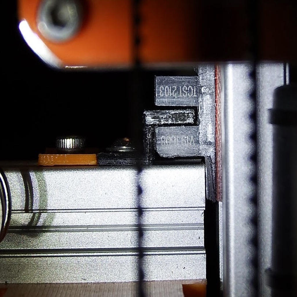
The solution is very simple, very reliable, very compact and very convenient - such a sensor does not interfere with any kind of work. The sensor is mounted on the frame of the printer (frame built from 3030 extrusion profile), so you do not need to add any wires to the cable connecting the table. In the final version, I will transfer the sensor to the back of the frame. After the transfer, it will become almost invisible, and in this place it will be practically impossible to hook it and move it, or bend it, or break it.
In the project files attached file details in SolidWorks format, as well as drawings of parts.
Highly accurate table adjustment
The proposed design of the sensor ALLOWS you to adjust the height of the triggering, but it is not designed to do this to the nearest tenth and hundredth of a millimeter.
I explain: I do NOT use the Z-endstop to determine the exact position of the hot bed and I do NOT need to set the Z -breaker with high accuracy. This Z-endstop only determines the position of the table when homing. After homing, a hot bed is heated; after heat up I perform autobedleveling for printing.
For exactly determine bedlevel position before start printing I use a home-made analogue of the BL-touch sensor with optical sensor and servodrive by brunofporto, project: https://www.thingiverse.com/thing:660257.
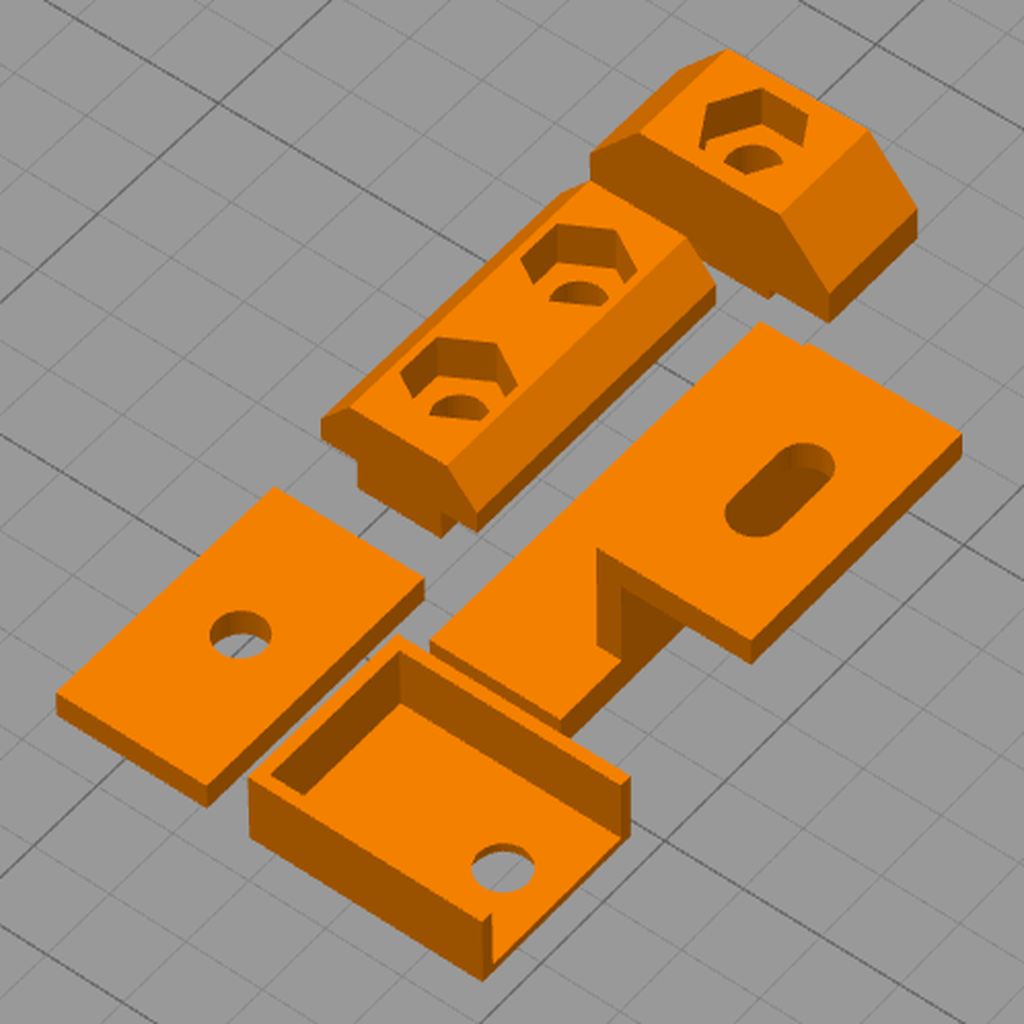
Sensor Details
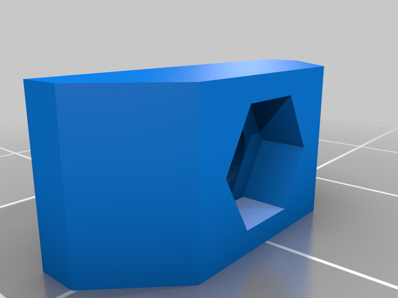
Breaker for opto-endstop
Black part part in the photo. It can move up and down to adjust the end stop trigger point. The breaker is made symmetrical so that it can be installed on the table beam both on the left and on the right. The breaker should be printed from a dark-colored plastic. Light-colored plastic cannot reliably interrupt the flow, so it will be necessary to additionally paint it with black paint (for example, acrylic paint or a permanent marker) or stick a piece of aluminum foil on it. The breaker is mounted with an M3 screw + M3 washer on one home-made plastic double T-nut for 2020 profile with a regular M3 nut inserted into it. But you can use the factory metallic T-nut, increasing the diameter of the hole for the M4 screw.
Guide plate (support)
The orange part in the photo. It allows the breaker to move only vertically, not allowing it to move left and right. This plate is installed once and no additional settings are required for it. The guide plate is fastened with an M3 screw on one homemade plastic double T-nut for 2020 profile with a regular M3 nut inserted into it. But you can use the factory metal T-nut by increasing the diameter of the hole for the M4 screw.
Sensor board
One sensor bracket (right in the photo) should have been cut (using a file) so as not to interfere with the movement of the table frame. The width of the sensor board is exactly 8 mm, as in the slot in the 3030 profile. The board is inserted into the slot exactly and without distortions. The cable is soldered to the sensor from the inside, and immediately goes into the slot on the profile. It is necessary to carefully make and control that the contact pads of the cable and the board tracks do not touch the aluminum profile. For reliability, I glued a piece of paper masking tape on the back of the board and carefully trimmed its protruding edges after installing the board on the profile. The board is installed on one homemade plastic T-nut. Here it is desirable to use a plastic T-nut, in order to exclude the possibility of a short circuit with a nut on the connections on the board.
Contact pad cover
Optionally. Its purpose - to protect the solder points from accidental shorting by any metal parts. Instead, you can apply a drop of hot melt glue. It is better to print it out of transparent plastic so that you can observe the glow of the LED indicator. Or, you can make an additional small hole in front of the LED mount.
Bill of materials
M3x8mm screw, DIN7991 - 1 piece (for endstop PCB);
M3x6mm screw, DIN7991 - 2 pieces (for breaker and guide);
M3 washer, DIN125A - 1 piece (for breaker);
M3 nut, DIN555 - 3 piece.
Installation tips
Lower the table frame below the beam 3030 into which the optical sensor will be installed. Install the optical sensor in the slot on the 3030 beam, but do not tighten its mount tightly. You should be able to move the sensor along the line of the slot.
Assemble the breaker and guide plate onto the double T-nut without tightening the screws. Insert the assembled assembly into the groove on the 2020 profile. Tighten the screws, but do not tighten the mount. You should be able to move the double nut, guide plate and breaker along the slot line. Temporarily move them closer to the middle of the table so that the breaker is guaranteed not to touch the sensor when lifting the table.
Carefully raise the table a little. Make sure the table frame does not touch the sensor housing. If necessary, further reduce the thickness of the sensor mount using a file. Make sure that the table frame never touches the sensor body when moving.
Move the table so that the top edge of the breaker is opposite the gap in the sensor. Move the sensor and breaker to the operating position. Tighten the screws of the sensor and the breaker (but do not yet tighten the screw that secures the guide plate!), Making sure that there is minimal clearance between the sensor and the breaker, and that the breaker does not touch the sensor. Make sure the switch is upright.
Move the table and make sure that the breaker reliably covers the sensor gap and does not touch the sensor when moving the table.
Pressing the guide firmly against the breaker, tighten the guide screw.
If necessary, loosen the breaker screw (only the breaker, but NOT the screw of the guide plate!) and adjust the vertical position of the breaker, making sure that the sensor works in the correct position of the table.
Once again check the operation of the table and the correct positioning of all the parts, and then finally tighten all the screws.
Additional photo
The full photo album of my printer is available at:
https://photos.app.goo.gl/VJPtnTUTJLTdHh8EA
:format(webp)/https://fbi.cults3d.com/uploaders/28920674/illustration-file/74057c7f-9e7d-41b2-8d4e-028183111182/DSCF4917-70.jpg)


/https://preview3d-images.cults3d.com/jcrtho6p70ftl6tk2bi0ap3nyad0)
/https://preview3d-images.cults3d.com/luqn4ixexl6q7ma7nyqb9s3fopch)
/https://preview3d-images.cults3d.com/mbeek11ttc5b00cqmdy5rh0sd1qk)
/https://preview3d-images.cults3d.com/7wkfk1joxx7nzl9d2ln44k2f4qwd)
/https://preview3d-images.cults3d.com/u7gpi7rfih1co86eia7bobm1cyaa)

