(Edit 2018-09-28 - Added 4b-v2.1 for v2.1 printers (which have a 10mm shorter distance between screw holes. Probably the same applies to the Plus as well.)
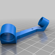
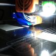
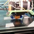
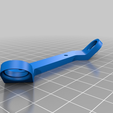
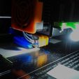
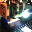
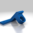
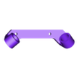
This is a bracket to hold one or two 10 mm diameter LEDs. It attaches in place of the stock part cooling fan using a pair of M3 screws and nuts.
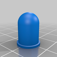
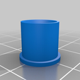
I eventually replaced my 10 mm LED with a pair of standard 5 mm LEDs. This requires the use of a spacer, the file for which is also included. It comes in two versions: The first is simply an open cylinder for a bare LED. The second, domed one is meant to act like a diffuser, and should be printed in a transparent/translucent plastic (white, natural, etc.). Lower infill doesn't save much time or plastic on either version, so I personally would just print at 100% infill.
Most people wire their LEDs in parallel with the 12V fan attached to the extruder heat sink, since it is always on when the printer is. If you can find a "DuPont female to 2 DuPont male" splitter and wire the LED with a female DuPont connector (or wire it directly to the splitter in place of one male connector), that might be easiest way to connect it to the printer without splicing into your existing fan wires. Alternately, you can make a splitter (see below). I've also seen these called JST connectors.
The LED will need a current-limiting resistor on the anode. Mine is made of a 220 ohm and a 100 ohm resistor in series (i.e. 320 ohms), which allows the LED to draw about 30 mA off the 12V fan line. I believe a typical 10 mm super bright white LED is rated up to 80 mA, but I am not sure what my LED was are, as I lack the datasheet. (I've since replaced this large LED with a pair of standard 5 mm white LEDs.)
I've also roughed up my LED's casing with sandpaper to give it a frosted look (in order to diffuse the light a little). I would recommend gluing the LED into the bracket so it won't come out during a print (using hot glue or whatever), and painting the back of it with an opaque paint to keep the light more where you need it. I painted mine with a few coats of FolkArt silver acrylic paint from Walmart.
There are multiple versions available:
Version 1 - The original, up-angled version. It was only that way because this started life as a variant of my X-Carriage Camera Mount (http://www.thingiverse.com/thing:1572909), but it might be useful if you need vertical clearance for some reason (like a Y-mounted camera (http://www.thingiverse.com/thing:1590678) ).
Version 2 - Added 2016-06-09. This has the mounting arm angled downward and offset to the left by 10 mm to match the nozzle.
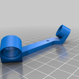
Version 3 - Added 2016-06-11. This version has two mounting arms, one on each end of the bracket (which is mostly to help illuminate parts behind the nozzle in the Y axis, as well as in front, but in theory will allow you to use it in combination with something else on the front fan bracket, like a diiicooler or the X carriage camera bracket linked above). You can mount LEDs in either or both holes, as you wish. The left arm is extended 10 mm to the left to put it a bit more in-line with the nozzle. I might change this and just alter the angle on that side.
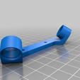
Version 4b - Added 2016-06-18. I've changed the angle of the bend to 60 degrees, rotated the LEDs by about 5 degrees, and extended the LED holder to help cut glare from the sides of the LED. Also extended the right arm a few millimeters for better clearance with the nut.
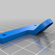
Version 4b-v2.1 - Added 2018-09-28. Version 4b, except the screw hole spacing is 30mm instead of 40 mm to accommodate the v2.1 and Plus)

/https://fbi.cults3d.com/uploaders/30152216/illustration-file/c1107a9c-4f13-46e1-8608-4b5b96400bc9/image.png)


