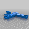
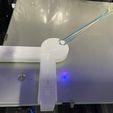
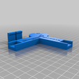
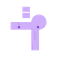
This is a tool to help you find the correct z-offset, x-offset, and y-offset for your BL Touch, CR Touch, or 3D Touch bed leveling probe.
Print all 3 parts and then super-glue the corner clips on the two tips as pictured. You will need a rubber band that can stretch over the opposite corner of your bed.
Update: Added Version2 for those who prefer X-marks-the-spot. Same instructions as below, it just uses X's instead of circles. (Might be a little easier to see when the nozzle touches the tool for z-calibration)
How to use this tool:
Step 1
Auto Home your printer without the tool in place.
Step 2
Raise the Z-Axis using the display panel about 100mm (Do not disable steppers).
Step 3
After you auto home your printer and raise the Z-Axis as stated above, place the tool in the front left corner of your print bed and then hold in place using a rubber band stretched over the peg and the opposite corner or your print bed. Make sure it is square, the tool and rubber bands should ensure that.
Step 4
Deploy your probe.
Step 5
Using your printer control panel (again, do not disable stepper motors), adjust the X and Y to position the probe directly over the center of the circle labeled PROBE. Slowly lower the Z-Axis until the probe barely touches the tool surface in the center of the PROBE circle. Your probe should then light up (and retract).
Step 6
Write down the current position of X, Y, and Z on your display panel. Label these positions X1, Y1, and Z1.
Step 7
Next, using the control panel again, position the nozzle directly centered over the circle labeled NOZZLE. Slowly lower the Z-Axis until the nozzle touches the center of the NOZZLE circle.
Step 8
Write down the current X, Y, and Z position on your printer display and label them X2, Y2, and Z2.
Step 9
Because the holes should be exactly 50mm apart, add 50 to the number you wrote down for X1. You can use digital calipers to verify. Some filaments expand or contract more than others.
BTW, If you need digital calipers or rubber bands I have provided a few links here:
Digital Calipers: https://amzn.to/48G64VR
Rubber Bands: https://amzn.to/46AjFMu
Step 10
If your probe is mounted to the left of your nozzle (usually the case)...
Subtract the X2 value from the X1 value and that is your X-offset.
Subtract the Y2 value from the Y1 value and that is your Y-offset.
Subtract the Z2 value from the Z1 value and that is your Z-offset.
Step 11 (Last one, I promise!)
Store these values in your printer, save, and remove the tool from your printer bed.
You can use your slicer software or Octoprint to set X, Y, and Z offsets if you cannot set them using your printer control panel. You can use G-Code before a print job starts to do this. For example:
M851 X-43; sets the x-offset to -43
M851 Y-6; sets the y-offset to -6
M851 Z-1.25; sets the z-offset to -1.25
M500; stores the settings. This M code may not work with all printers.
When you auto-level your bed, the leveling probe points should all be equal distances from the edges. The center position should be exactly in the center.
Notes:
It is possible on some printers that X-Axis cannot go all the way to the edge of the bed surface. This is why your bed surface is usually 235mm x 235mm (on and Ender3 for example), but your build space is 220mm x 220mm. This is because the end stop for the X-Axis prevents the hotend from going all the way to the left. If you look at it closely when you auto-home, you will see that the nozzle cannot go all the way to the edge without hitting the X end stop switch. This is normal and part of the printer design.

/https://fbi.cults3d.com/uploaders/30391954/illustration-file/84dc6a60-7011-4ccd-8a7a-a5421e202450/b6dd412e-87b4-46b7-8881-65fe4cf86f52.png)
