Skip to content

Anycubic I3 Mega Hemera (Hermes) Mount Full Voume

Advertising
Advertising
?
Creation quality: 5.0/5 (1 vote)
Evaluation of members on the printability, utility, level of detail, etc.

  • 635 views
  • 6 downloads

License
3D design format
Folder details Close
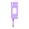
  • BLTouch-PCB_Mount_V7.step
  • BLTouch-PCB_Mount_V7.stl
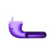
  • Part_Cooler_V7.step
  • Part_Cooler_V7.stl
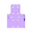
  • X-Belt_Holder_V5.step
  • X-Belt_Holder_V5.stl
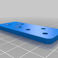
  • X-Plate_V7.step
  • X-Plate_V7.stl
  • Y-Belt_Adapter.step
  • Y-Belt_Adapter_V1.stl
  • Y-Carriage_Adapter_V1.step
  • Y-Carriage_Adapter_V1.stl

Learn more about the formats

Publication date 2023-10-06 at 22:54
?
Published to Thingiverse on: 2020-06-10 at 09:13
Design number 1498158

3D printer file info

3D model description

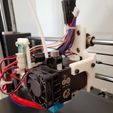
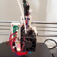
This is an E3D Hemera mount for the Anycubic I3 Mega with BL Touch and a 4020 blower fan and part cooler. The Hemera is mounted 90 degrees from the usual orientation that you see with other designs so that you can retain the original print volume of the i3 Mega (other designs lose about 10-15 mm in the X direction).

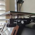
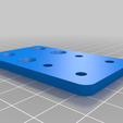
The nozzle is almost in the same location as the original nozzle, but is shifted about 33mm forward. We compensate by shifting the bed 33mm forward using adapter plates. The adapter plates raise the bed 4mm, but since we are using auto bed leveling, we replace the springs on the bed with M3 nuts and the bed can sit 4mm lower on the Y-carriage (see photos).

The BL Touch mount point is as close as possible to the nozzle, so that you can get an accurate reading of the entire bed, in fact, because there is ~5mm of X movement you can utilize and the sensor is only 20mm away from the nozzle, you are only basically missing the right 15 mm of the bed. The sensor can reach all of the Y coordinates and all the way to the left on the X axis.

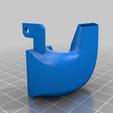
The part cooler sucks, but it works, eventually I will redesign it.

I have numerous other upgrades to the Anycubic i3 Mega which I won’t cover here, other people have done a much better job. But I’ll list them:

  • Corrected Z-Wobble with 5mm to 8mm flex couplings and 6.5 mm steel ball bearings
  • Replaced power supply fan with Noctua NF-A9x14 PWM and 3 pin to 2 pin Cable Adapter. Used existing metal power supply shroud and cut opening with metal nibbler tool (https://www.amazon.com/ProsKit-900-215-Nibbler) and drilled mounting holes.
  • Replaced control board cooling fan with Noctua NF-A8 FLX, 3 pin to 2 pin Cable Adapter and this https://www.thingiverse.com/thing:3444423
  • Replaced Trigorilla control board and original TFT with SKR 1.4 Turbo and TFT35 v2.0

Bill of Materials for Mounting

Bill of Materials Others

  • Hemera Kit
  • BL Touch
  • 4020 Blower Fan

Hemera Installation

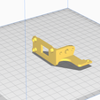
  1. 3d print everything (3 x Y-Carriage Adapter), rotate the X-Belt Holder apporpriately and rotate the BLTouch/PCB Mount as pictured. Print everything with 100% infill. The part cooler and the BLTouch/PCB holder need supports. Those two parts were printed with supports everywhere that had an 80 degree overhang angle. All other parts do not need support.
  2. Also 3d print a spool holder that can sit on top of the i3 Mega, I use https://www.thingiverse.com/thing:3237221 there are plenty of options.
  3. Remove the existing hotend, part cooler, hotend cooler, shroud, x-plate, belt adapter, and PCB. Save all the parts.
  4. Prep the hemera per the instructions. Some great tips at https://gist.github.com/LongLiveCHIEF/eea2b91bebe4fa5d107493f76cb002bc notably, calibrate your e-steps before attaching the nozzle. The Hemera ships with a 30W heater cartridge, the original heater cartridge is 40W so I reused the original (no need to cut/adjust wiring). The original thermistor does not fit in the new heater block so I used the Hemera one. Cut and solder the original connector to the new thermistor or crimp a new one.
  5. Prep the 4020 Blower Fan as the part cooler fan by cutting and soldering the original connector to the new thermistor or crimping a new one.
  6. Prep the Hemera Cooling Hot End Fan as the part cooler fan by cutting and soldering the original connector to the new thermistor or crimping a new one.
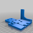
  7. Use 2 x 8mm M4 Cap Head Bolts and 2 x M4 Nuts to attach the X-Plate to the X-Belt holder.
  8. Use the original 8mm M4 Button Head Bolts to attach the X-Plate to the rails.
  9. Zip tie the X-Belt to the X-Belt holder with the appropriate tension (should be roughly the same as the original)
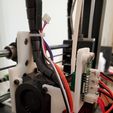
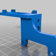
  10. Install the BL Touch onto the BLTouch/PCB Mount using 2 x M3 Nuts and 2 x 8mm M3 Flat Head Bolts, the taper helps centering of the sensor. The logo faces inwards and the cables route out the front (see photo for reference). Do not over tighten.
  11. Install the original PCB onto the BLTouch/PCB Mount using 3 x M3 Nuts and 3 x 8mm M3 Flat Head Bolts. Tighten down until the tapers have a firm grip on the PCB.
  12. Loosely Install the Hemera on to the X-Plate with 3 x 8mm M3 Cap Head Bolts on the right side (with 3 x included square M3 Nuts) and the 4020 Blower Fan and a 20mm M3 Cap Head Bolt on the left side (with 1 x included square M3 Nut).
  13. Loosely install the BLTouch/PCB mount with a 20mm M3 Cap Head Bolt thru the top of the 4020 Blower Fan.
  14. Loosely install the part cooler between the bottom of the 4020 Blower Fan and the BLTouch/PCB mount with a 20mm M3 Cap Head Bolt thru the bottom of the 4020 Blower Fan.
  15. Tighten all the bolts.
  16. Plug in all your cables. I recommend using hot glue to attach the JST-XH connectors to the PCB. Zip ties the bundle to the back of the X-Plate thru the two small holes at the top.

Hotbed Installation

  1. Cut and remove the zip tie on the hotbed cable.
  2. Remove all 4 thumbs wheels on the hotbed, make a note of the position of the bed relative to the Y-Carriage, we will need to install it back about 4-5 mm lower.
  3. Lift up the hotbed and remove the 4 springs, we won’t need them.
  4. Remove the 15 Cap Head Bolts securing the Y-Carriage to the rails and the Y-Belt and set aside the Y-Carriage.
  5. Put the 15 x M4 Nuts onto the Y-Carriage Adapters (3 x) and the Y-Belt Adapter, they should stay in place after inverting due to friction. If they don’t stay you will need to hold them in place when installing the Y-Carriage or optionally use a small drop glue to help them stay temporarily.
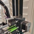
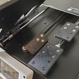
  6. Attach the Y-Carriage Adapters (3 x) and the Y-Belt Adapter to the rails and Y-Belt respectively, using 15 x 8mm M4 Flat Head Bolts. The Y-Carriage mounting holes with the M4 nuts in place should point towards the front of the printer (see photos).
  7. Attach the Y-Carriage to the Y-Carriage Adapters (3 x) and the Y-Belt Adapter with the original 15 x 8mm Button Head Bolts.
  8. Put 4 x M4 Nuts on the Hotbed at about the same depth, to lower the hotbed so that it sits about the same level as it was before (should be around 4mm less than what the springs were pushing up).
  9. Install the hotbed on the Y-Carriage and replace the thumb wheels loosely.
  10. Roughly level the hotbed with the new Hemera nozzle, using the M4 nuts to adjust the height and then the thumb screws to lock it in place. It doesn’t have to be super accurate since auto bed leveling will take care of the fine adjustments.Quick leveling of all four corners with a piece of paper will work. Note, the tightening down of the thumb screw will move the hot bed down slightly.
  11. Tighten all the thumb screws and zip tie the hotbed cable to the back right thumb screw (not the bolt of the bed).

Final Installation

  • Update the firmware with the appropriate settings
  • Do auto bed leveling:

    -- Heat Bed and Nozzle to first layer print temperatures
    M851 Z0; zero the probe z offset
    M500; save to eeprom
    G28; home everyhing
    G29; do the auto bed leveling
    M500; save to eeprom
    G28; home everything
    M501; load from eeprom
    M420 S1; enable mesh
    M211 S0; disable sotware end stops
    G1 Z5 X110 Y110 F2000; move to the center of the bed
    G1 Z0; move z ro zero
    -- Use G1 Zx.xx coomands to bed level the nozzle with a piece of paper
    G114; get the current z then subtract 0.10 (thickness of paper) to get the nozzle distance to the bed
    G851 Z[number from above]; set the probe to nozzle z offset
    M500; save to eeprom
    M211 S1; ensable sotware end stops
    G28; home everything
    G29; re do bed levelling with probe z-offset
    M500;
    G28; home everything
    M501; load from eeprom
    M420 S1; enable mesh
    M211 S0; disable sotware end stops
    G1 Z5 X110 Y110 F2000; move to the center of the bed
    G1 Z0; move z to zero
    -- paper should not be able to slip under the nozzle (nozzle should be right at the bed)

  • Print a calibration cube and fine tune e-steps ond/or flow

Firmware Notes

  • Not a full guide here, there are plenty of much better guides available
  • Configure Bilinear Auto Bed Leveling
  • Configure BL Touch

  • define NOZZLE_TO_PROBE_OFFSET { -20, -2, 0 }

  • define X_BED_SIZE 220

  • define Y_BED_SIZE 220

  • define X_MIN_POS -3

  • define Y_MIN_POS -5

  • define Z_MIN_POS 0

  • define X_MAX_POS 225

  • define Y_MAX_POS Y_BED_SIZE

  • define Z_MAX_POS 205

Cura Notes

  • Not a full guide here, there are plenty of much better guides available
  • Update X/Y of Machine profile to 220mm and 220mm
  • Reduce retraction distance to 0.5mm and retraction speed to 30mm/s

  • Start G-Code
    G21 ;metric values
    G90 ;absolute positioning
    M82 ;set extruder to absolute mode
    M107 ;start with the fan off
    G28 X0 Y0; move to edge of bed
    G28 Z0;
    M501 ;restore EEPROM to use mesh leveling
    M420 S1 ;enable mesh leveling
    G1 X-3 Y-3 F{speed_travel} ;move off the edge of the bed
    G1 Z3.0 F{speed_travel} ;move the platform to 3mm
    G92 E0 ;zero the extruded length
    G1 F200 E15 ;extrude 15mm of feed stock
    G92 E0 ;zero the extruded length again
    G1 F{speed_travel}
    M117 Printing...
    G5

  • End G-Code
    M104 S0 ; turn off extruder
    M140 S0 ; turn off bed
    M107 ;fans off

    G91 ;relative positioning
    G1 E-1 F300 ;retract the filament a bit before lifting the nozzle, to release some of the pressure
    G1 Z+0.5 E-5;

    G90 ;absolute positioning
    M211 S1 ; make sure soft end stops are on for the next move
    G1 X0 Y220; move X min and Y max, so the bed is presented
    M84 ;steppers off

Other Notes

  • I undersized all the M4 screw holes on the X-Plate so the need to be widened with a drill, the M3 holes are correctly sized.
  • The Anycubic i3 Mega has a 220 x 220 bed, and you can use the entire bed if you want.
  • I have an SKR 1.4 Turbo with TMC 2209 stepper drivers, I still use the micro switches for limits.I have included my configuration.h and configuration_adv.h if you want to see all the X/Y parameters
  • I don’t have a filament runout sensor attached at the moment, but I plan to put one back at a later time.
Advertising


Issue with this design? Report a problem.

Would you like to support Cults?

You like Cults and you want to help us continue the adventure independently? Please note that we are a small team of 3 people, therefore it is very simple to support us to maintain the activity and create future developments. Here are 4 solutions accessible to all:

  • ADVERTISING: Disable your banner blocker (AdBlock, …) and click on our banner ads.

  • AFFILIATION: Make your purchases online by clicking on our affiliate links here Amazon.

  • DONATE: If you want, you can make a donation via Ko-Fi 💜.

  • WORD OF MOUTH: Invite your friends to come, discover the platform and the magnificent 3D files shared by the community!


Sharing and downloading on Cults3D guarantees that designs remain in makers community hands! And not in the hands of the 3D printing or software giants who own the competing platforms and exploit the designs for their own commercial interests.

Cults3D is an independent, self-financed site that is not accountable to any investor or brand. Almost all of the site's revenues are paid back to the platform's makers. The content published on the site serves only the interests of its authors and not those of 3D printer brands who also wish to control the 3D modeling market.

100% secure payment by credit card, PayPal, Apple Pay, Google Pay, etc.
View all payment options.